LIGHT FLUX REGULATORS CATALOGUE 2020 - DSSTech Srl
←
→
Page content transcription
If your browser does not render page correctly, please read the page content below
LIGHT FLUX REGULATORS
CATALOGUE
2020
Our products for public lighting

         CENTRALIZED SYSTEMS

        POINT TO POINT SYSTEM

KNOW-HOW, EXPERIENCE AND QUALITY: OUR STRENGHT

Quality is our philosophy of business.
Since 2004, our company is UNI ISO 9001 certificated, which regards the entire
production, starting from the project, to production, until final tests of each piece,
including after-sale assistance.
Being certificated means being committed to maintain high standard production targets,
which are our customers' guaranty and satisfaction, especially for our best quality/price
relationship.
The Varibox
system
CENTRALE - VI - ITALY
The VARIBOX control systems have been designed to operate in the civil and industrial lighting field in a
increasingly sensitive to energy problems and its costs context.
They introduce the concept of energy saving by acting on the technical characteristics of electroluminescent
lamps for which, within certain limits, the supply voltage variation will modify the effect of light in a human eye not
perceived way.
Two other important technical issues to highlight are:
1) the systems are automatic, so they can operate according to preset timings;
2) the systems are programmable and allow you to customize the operating cycle depending on the needs.
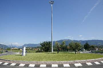
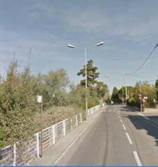
1 - Application
This product family is designed to be applied in all electrical multiple-light systems such as existing roads,
parking lots, parking areas, diffuse illumination areas in the civil and industrial field.
2 - Energy saving
By installing a control unit with flux regulator you can normally ensure consumptions savings between 30% and
33% (these values have been detected on public roads illuminated with 70W to 250W sodium vapor lamps).
The lamps voltage, supplied by the center console, is controlled and kept constant by an electronic
microprocessor.
3 - Saving maintenance costs
In addition to consumptions savings, the system carries substantial savings also on maintenance costs in the
audited systems. In particular, managing the lamp’s ignition program and reducing the peaks and voltage
imbalances, it can increase the lamp’s life by 40%.
4 - Control System
The energy module constantly detects and monitors voltage, current, power and power factor, active, reactive
and apparent energy and it displays them on alphanumeric panel or touch-screen.
The control unit is composed by a latest-generation microprocessor that controls and manages the plant’s
functions, sending the instructions to external controls according to the instructions that reside in the operating
program.
5 - User interface
The interface is formed by a 4” color touch-screen with memory.
With the alarm and consumption remote management kit you can remotely manage the system via internet
connection using VNC software.
6 - Reliability
We design Varibox family with the goal of maximum reliability because this is the main feature our customers are
asking for. To obtain such result we use an electromechanical solution to manage the ux regulation. We use top
quality components and materials and we carefully test every single equipment.
Single-phase / Three-phase management

                                                                                                                          MARANO VICENTINO - ITALY

 The VARIBOX system
 Suitable for existing installations with mercury vapor lamps, high and low pressure sodium, metal halide and LED*.
 It’s possible to install a single-phase or three-phase enclosure which will still provide 230V/50Hz single-phase outputs with
 adeguate power to the number of controlled lamps.
 The lamps power supply line is connected to the electrical cabinet terminals and the control unit, suitably programmed, will
 handle the lighting system in an automatic way.
 If requested, it’s possible to install a device to remotely control the system, that allow you to manage the functionalities and obtain the
 principal parameters and any triggered alarms.

                                                                                                                               +40%
                                                                                                                             lamp’s life

                                SL1

                         DIF

        F            AREA
        N         FRAMEWORK

 * : Varibox system in combination with dimmable LED lamps.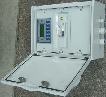
Principle of operation

                                                             MARANO VICENTINO - ITALY

   How a lamp works with a conventional ferromagnetic ballast

                                   Unstable
   Voltage                          voltage
   spikes
power

                Lamp continuously operates at max

              time
                     How a lamp works with Varibox system

                                                            30%
                                                            savings
power

              time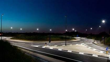
Technical and constructive features

TECHNICAL FEATURES                                                                                         VARIBOX

Supply voltage                                                                                    400V+N / 230V +/- 10%

Power Frequency                                                                                        50 Hz / 60 Hz

Supply voltage stability                                                                                     95%

Introduction of harmonic distortion at the output                                                           none

Nominal insulation voltage                                                                                  1000V

Reference norms                                                                             EN 60529 - EN 62208 - EN 62262

Protection degree                                                                                           Ip65

CONSTRUCTIVE FEATURES

Cabinet with class 2 double insulating

Reinforced polyester with glass fiber, flame retardant and halides free materials

Automatic/Manual by-pass system in case of control equipment’s failure

Modular twin-socket type service socket, protected by 10A circuit breaker. F + N + Earth

Overvoltage protection arresters

Microprocessor controller with touch screen interface

Magneto-thermal protection switch with Icc > 15 kA

Fixed self-resetting differential circuit breaker with 300mA sensitivity

Adjustable sensitivity twilight switch (or, alternatively, astronomical clock)

Magneto-thermal breakers to protect the three single-phase output lines according to the installed power

Internal temperature control device with fan intervention settable threshold

Heating device for internal humidity elimination (optional)
Functional features

FUNCTIONAL FEATURES

Operation with sodium vapor, mercury vapor, metal halide lamps and LED*

Gradual ignition with network peaks attenuation

Gradual re-ignition integrated system in case of accidental shutdown

Automatic/Manual by-pass system in case of control equipment’s failure

Luminous flux reduction cycles programming

Time bands programming with adjustable flow values

Multivoltage static regulation system

Continuous control over the three phases

Remote control via alarms and consumption detection management kit (optional)

Monthly / yearly consumption and alarms report sending (optional)

Adjustable ignition and turning off ramps (voltage and time)

Low buffer battery alarm

 * : Varibox system in combination with dimmable LED lamps.
Remotely management

                                                                                                                    MARANO VICENTINO - ITALY

Operation
Applying to the cabinets the alarm and consumption management kit, it will be sent, via email, real-time alarm signals and '.csv' files
with the monthly and annual consumptions recordings.

Alarms

     1. "Low power". When the detected system power is lower than a set minimum threshold value.
     2. "Low voltage". Through a programmable minimum threshold management you can detect the line’s voltage
        fluctuation. If the fluctuation takes place during the controller's set voltage maximum reduction phase, the controller
        will switch to the upper step to ensure the line regular operation.
     3. "Low battery". When the date chip buffer battery's voltage level drops below the minimum threshold value.
     4. "Thermal trip". When the automatic recovery system has exhausted the number of reset attempts (number set up in
        the reset device) the line is no longer supplied, and then the alarm signaling is activated.
     5. "Not enough space". If the available memory for the recording of monthly and annual consumption is no longer
        sufficient. The chosen programming requires that, every twelve months, data are overwritten and therefore this alarm
        has the goal to control that memory remains efficient.

The alarm signalings are sent via email to one or more addresses stored in the equipment.

Documentation

To offer to the system operator the ability to evaluate the line's efficiency, the controller, every month's first day, at evening
ignition, send an email with a 'csv' file containing 28-31 lines (depending on months) with the detected daily consumption of
active energy.
Every year’s first day of January, always on the evening ignition, the cabinet will send, in addition to the previous month's
consumption email, two other emails with the 'csv' files containing respectively:
      • last year’s consumption: 12 rows related to the last year's consumption, month by month;
      • list of sent alarm signalings indicating the alarm's type (the conductor can choose to be informed of the alarm
           messages monthly or yearly).

Remote management with VNC

Using VNC viewer you can remotely connect to the cabinet's operator panel. The link allows you to manage all the controller's
offered features in addition to allowing the displaying of all electrical values, as it would be possible if you were physically
working in front of the flow regulator.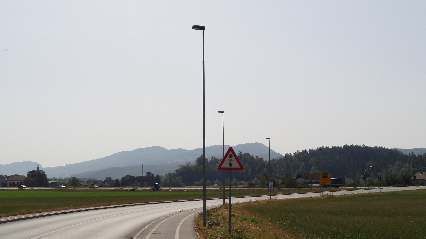
Varibox enclosures

                                         DRAGOMEL - SLOVENIA

The VARIBOX systems in public lighting

                                            Measures compartment

                                            AUT/MAN switch.

 Control panel

Magnetothermic protection
    with differential

magnetothermic protection
    for output lines
                                                               Light
                                                               probe

                         Input line

                        Lamps line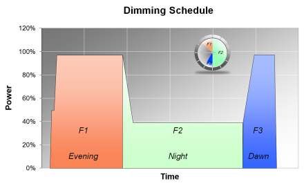
Single
       compartment
         EL series

                                                                                             DOMZALE - SLOVENIA

All the luminous flux regulator electrical and electronic equipment is housed in a polyester glass fiber box, suitable
for harsh outdoor environments, provided with protection plinth and roof top.

Each component is fixed in the housing compartment on the bottom galvanized steel sheet, insulated from the live
parts thanks to the main structure and to a series of front panels, made in insulating material, on some of which
are frontally installed programming, security and control equipment.
The door with key lock adopts an airtight seal complies with IP65 standards.
The forced ventilation system is activated by an internal temperature sensor and maintains the inner environment
in ideal climatic conditions even in particular areas and periods.
The light probe activates the system at dusk and turns automatically off at dawn.

         Enclosures: models and measures

                El421 series
                1050x550x350 mm

                El433 series
                1050x800x350 mm

                El533 series
                1300x800x350 mm

                El633 series
                1300x1050x350 mm
Products overview EL421 series Varibox code Article Dimensions EL 421/2.1 flux regulator enclosure 2KVA / 230Vac 1050 x 550 x 350mm EL 421/4.1 flux regulator enclosure 4KVA / 230Vac 1050 x 550 x 350mm EL 421/6.1 flux regulator enclosure 6KVA / 230Vac 1050 x 550 x 350mm EL 421/8.1 flux regulator enclosure 8KVA / 230Vac 1050 x 550 x 350mm EL433 series Varibox code Article Dimensions EL 433/6.1 flux regulator enclosure 6KVA / 3x400V + N 1050 x 800 x 350mm EL 433/7,5.1 flux regulator enclosure 7,5KVA / 3x400V + N 1050 x 800 x 350mm EL 433/9.1 flux regulator enclosure 9KVA / 3x400V + N 1050 x 800 x 350mm EL 433/12.1 flux regulator enclosure 12KVA / 3x400V + N 1050 x 800 x 350mm EL533 series Varibox code Article Dimensions EL 533/15.1 flux regulator enclosure 15KVA / 3x400V + N 1300 x 800 x 350mm EL 533/18.1 flux regulator enclosure 18KVA / 3x400V + N 1300 x 800 x 350mm EL 533/21.1 flux regulator enclosure 21KVA / 3x400V + N 1300 x 800 x 350mm EL 533/24.1 flux regulator enclosure 24KVA / 3x400V + N 1300 x 800 x 350mm EL633 series Varibox code Article Dimensions EL 633/30.1 flux regulator enclosure 30KVA / 3x400V + N 1300 x 1050 x 350mm EL 633/37.1 flux regulator enclosure 37KVA / 3x400V + N 1300 x 1050 x 350mm
Double compartment EL series
        (with measures compartment)

                                                                                                                MARANO VICENTINO - ITALY

All the luminous flux regulator electrical and electronic equipment is housed in a polyester glass fiber box,
suitable for harsh outdoor environments, provided with protection plinth and roof top.

The enclosure is divided into two compartments:
1) upper compartment to place the energy meter. This compartment has an independent closure with its own
removable key with and is equipped with an inner perimetral seal which complies with IP65 standards;
2) lower compartment for the power and control equipments. All flow regulator’s electrical equipment are fixed
on a bottom galvanized steel, insulated from the live parts thanks to a series of front panels, on some of which
are frontally installed programming, security and control equipment.
Also this compartment has a door with an independent key lock, with a sealing system that complies with
IP65 standards.

The inner forced ventilation system is activated by a temperature sensor that keeps the enclosure’s environment
in ideal climatic conditions even in particular areas and periods.
The detector light probe activates the system at dusk and turns automatically off at dawn.

             Enclosures: models and measures

                           KIT EN500 series
                           500x500x320 mm

                           KIT EN750 series
                           500x750x320 mm

                           KIT EN1000 series
                            750x1000x320 mm
Products Overview EN500 KIT Code Article Dimensions KIT EN 500 Measures compartment kit for single-phase enclosures 500 x 500 x 320mm EN750 KIT Code Article Dimensions KIT EN 750 Measures compartment kit for three-phase enclosures (up to 24 KVA) 500 x 750 x 320mm EN1000 KIT Code Article Dimensions KIT EN 1000 Measures compartment kit for three-phase enclosures (over 24 KVA) 750 x 1000 x 320mm
Pole mount CTBX
      200 Controlbox

                                                         ZUGLIANO - VI - ITALY

Lampposts lines feeding box for public lighting

                            Control panel

                                                    Thermal magnetic
                                                  Differential protection

                                                    Automatic/Manual - Selector

                                                      Brightness adjustment

                                                                  Light probe

               Input Line

             Lamps Line
ACTBX 300
Controlbox
enclosure
DOMZALE - SLOVENIA
Lampposts lines feeding enclosure for public lighting
- Operation with sodium vapor, mercury vapor, metal halide lamps and LED.
- Optional adding of alarms and consumption remote management kit.
- Various sizes available, depending on the power that must be managed.
- Available with measures compartment.
Measures Compartment
Automatic / Manual
Selector
Control Panel
Thermal Magnetic protection
with differential device
Light probe
Input Line
Lamps Line
* : Controlbox system in combination with dimmable LED lamps.ALSYVAR series electronic
programmable ballast
DOMZALE - SLOVENIA
DESCRIPTION
Electronic luminous flux regulator suitable to be used in
public lighting.
The programmable electronic ballast is equipped with a
microprocessor that automatically adjusts the lamp’s
operation according to the environmental light and the
changing seasons thanks to an internal astronomical
system.
Vertical
Mounting It is mounted inside the streetlight door, away from heat
sources, ensuring the module life’s lengthening.
Possibility to regulate the luminous flux to adapt the night
lighting according to the road’s use conditions.
With the luminous flux reduction during the middle of the
night you can get energy savings up to 60% if compared to
the common ferromagnetic ballast management.
OPERATION OPERATING DIAGRAM
A central unit placed at the beginning
(see CTBX and ACTBX series) of the
line and controlled by a twilight probe
enables at dusk and disables at dawn
the road’s, parking’s and square’s
lighting.
The system can be used in new or
existing lighting systems where sodium
vapor lamps are installed.
An hour before dawn, when urban
traffic restarts, the system automatically
brings the lamp at full brightness and
than turns it off thanks to the twilight
sensor.ALSYVAR series electronic
programmable ballast
VITROLLES - FRANCE
PROGRAMMING
Power Reduction % Last hour
DP3 DP2
no Time Reduction
DP4 DP1
Programming
Vertical Mounting
Double insulation (L - N) 4 KV
Lamp
L
N
Power supply
230Vac
TECHNICAL DATA
- Power supply from 190 Vac to 260 Vac/50Hz
- Reduced power consumption max = 60%
- Phase displacement with power factor cos = 0.99
- Night reduction time insertion
- Last hour programming with return to maximum power
- Consumption reduction = 0 - 20% - 40% - 60%
SYSTEM STRENGTHS PRODUCT RANGE
1 - Self-learning procedure during the first night Model Power Lamp
2 - Extension of lamp's life + 40%
3 - Instant start with hot lamp
4 - Reduction of maintenance costs
ALSYVAR-70 70W HPS70
5 - Network independent stabilized power supply ALSYVAR-100 100W HPS100
6 - Removes ballast, starter, capacitor ALSYVAR-150 150W HPS150
7 - Very easy to install
8 - Constant power maintenance over time
9 - Thermostatically controlled and self-protected system
10 - Protection against network’s peak
11 - System with built-in astronomical clockMINIVAR series electronic
programmable ballast
ROGNAC - FRANCE
DESCRIPTION
Electronic luminous flux regulator suitable to be used in
public lighting.
The programmable electronic ballast is equipped with a
microprocessor that automatically adjusts the lamp’s
operation according to the environmental light and the
changing seasons thanks to an internal astronomical
system.
The module is mounted in the lamp ceiling light; its
thermostat constantly measures the inner ambient
temperature and reduces the output power when it
reaches the temperature threshold, preserving the module
integrity .
Possibility to regulate the luminous flux to adapt the night
lighting according to the road’s use conditions.
With the luminous flux reduction during the middle of the
night you can get energy savings up to 60% if compared
to the common ferromagnetic ballast management.
OPERATION
A central unit placed at the beginning OPERATING DIAGRAM
(see CTBX and ACTBX series) of the
line and controlled by a twilight probe
enables at dusk and disables at dawn
the road’s, parking’s and square’s
lighting.
The system can be used in new or
existing lighting systems where sodium
vapor lamps are installed.
An hour before dawn, when urban
traffic restarts, the system
automatically
brings the lamp at full brightness and
than turns it off thanks to the twilight
sensor.MINIVAR series electronic
programmable ballast
DOMZALE - SLOVENIA
PROGRAMMING
DP2 DP3
Last hour Power Reduction %
DP1
Time Reduction DP4
Programming
Double insulation (L - N) 4 KV
Lamp
CARATTERISTICHE TECNICHE
L
N
Power supply
230Vac
TECHNICAL DATA
- Power supply from 190 VAC to 260 VAC/50Hz
- Reduced power consumption max = 60%
- Phase displacement power factor cos = 0.99
- Entering hours night reduction
- Last hour programming with the return to maximum power
- Reduced consumption = 0 - 20% - 40% - 60%
SYSTEM STRENGTHS PRODUCT RANGE
1 - Self-learning procedure during the first night Model Power Lamp
2 - Extension of lamp's life + 40%
3 - Immediate start with hot lamp
4 - Reduction of maintenance costs ALSYVAR-70 70W HPS70
5 - Network independent stabilized power supply ALSYVAR-100 100W HPS100
6 - Remove ballast, starter, capacitor ALSYVAR-150 150W HPS150
7 - Very easy to install
8 - Constant power maintenance over time
9 - Thermostatically controlled and self-protected system
10 - Protection against network’s peak
11 - System with built-in astronomical clockStreet lighting with COMBIVAR series
electronic programmable ballast
ZABORST - SLOVENIA
DESCRIPTION
COMBIVAR is the combination of two very high quality products: a high
energy saving dimmable electronic ballast and an elegant and modern
street lighting.
This interesting made in Italy technical and constructive combination
puts togheter speed, ease of installation and a great price.
The street lighting is wired and programmed at the factory so that the
installer is left alone only for the pole mounting and for the network
electrical connection.
The system can be used in new or existing installations where it is
necessary to change the armor, or the lamp's type conversion, e.g. from
mercury vapors to sodium vapors.
OPERATION
COMBIVAR is ideal to illuminate urban and suburban streets, car parks,
ARMOR: gardens: it works with 70W, 100W, 150W HPS lamps and thanks to the
Body, opening hook, aluminum cover and electronic ballast's characteristics, it can achieve over 60% energy
die-cast fixing block. savings, compared to ferromagnetic ballasts.
Fixing block suitable for poles with d = 60
mm.
Paintwork: thermosetting polyester
powder.
Protective glass: 4mm toughened.
Hinged to body through a AISI 306
stainless steel pin. OPERATIVE DIAGRAM
Optics: 99.85 aluminum pure anodised
and polished cut-off. Adjustable lamp's
focus to optimize the optical
performance.
BALLAST:
The electronic flow regulator with quick
programming through dip-switches to set:
- flux reduction’s time
- maximum power return
- reduction levels (0 - 20% - 40% - 60%)
Reduction time self-learning,
independent from the installed ignition
system.
Increase of lamp’s life of 50% thanks to
the electronic intelligent management of
ignition / heating / power regulation
phases.
Overheating protection with thermostatic
safety probe.
Electronics with voltage stabilizer and
protection from shocks and surges.
Lamp’s hot re-ignition.
High power factor (cos-fi> 0.99).COMBIVAR and GARDEN street
lighting series with electronic
programmable ballast
ZABORST - SLOVENIA
ROAD
( Armor + Ballast + HPS lamp )
COMBIVAR
70W / 100W / 150W
STREET FURNITURE
( Armor + Ballast + HPS lamp )
GARDEN
70W / 100W / 150WDOC. EMC-REB150
DATA: 14.05.2009
LABORATORI DI PROVA Pagina: 1 di 48
Allegati pagine da 23 a 48
RAPPORTO DI PROVA
TEST REPORT
N. 15.RA09 redatto il 14.05.2009
IDENTIFICAZIONE CLIENTE Rasotto s.n.c.
Customer/Manufacturer Identification Via dell’Artigianato, 3
36034 – Molina di Malo (Vicenza)
RESPONSABILE PER IL CLIENTE Sig. F. Rasotto
Customer/Manufacturer Responsible
APPARECCHIATURA SOTTO PROVA Tipo: Ballast elettronico per lampade al sodio ad alta pressione
System under test
Modello: REB150
s.n.: campione di preserie
Appartenenti Famiglia di prodotto: REB150-REB100-REB70
NORME DI PRODOTTO APPLICATE EN 55015 (Limiti e metodi di misura delle caratteristiche di ed. 2006
Product standards applied radiodisturbo degli apparecchi di illuminazione elettrici e degli
apparecchi analoghi)
EN 61547+A1 (Apparecchiature per illuminazione generale – ed. 1995
Prescrizioni di immunità EMC)
EN 61000-3-2 (Limiti di Emissione di Corrente armonica) ed. 2006
EN 61000-3-3+A1+A2(Limiti di Emiss.e Flutt. tensione / Flicker) ed. 1995
NORME DI BASE APPLICATE EN 61000-4-2+A1+A2 (Immunità alle scariche elettrostatiche) ed. 1995
Basic standards applied EN 61000-4-3 (Immunità ai campi EM a radiofrequenza irradiati) ed. 2006
EN 61000-4-4 (Immunità ai Fast Transient e Burst) ed. 2004
EN 61000-4-5 (Immunità al SURGE ) ed. 2006
EN 61000-4-6 (Immunità condotta al campo indotto a RF) ed. 2007
EN 61000-4-8+A1 (Immunità al campo magnetico a 50 Hz ) ed. 1993
EN 61000-4-11 (Immunità a interruzioni e buchi di tensione) ed. 2004
DOCUMENTI DI RIFERIMENTO Piano di Prova per la marcatura CE
Reference documents
Il Piano delle Verifiche è stato concordato con il cliente in base
agli attuali requisiti di marcatura e alle specifiche richieste del
prodotto.
SCOPO DELLE PROVE Qualificazione del prodotto a scopo marcatura C E s econdo i
Nature of Testing requisiti della Direttiva di prodotto 24/108/EEC (Compatibilità
Elettromagnetica)
DATA INIZIO PROVE 24.04.2009
Start test date
DATA FINE PROVE 08.05.2009
End test date
DATI LABORATORIO DI PROVA ETL Laboratorio di Prova s.r.l.
Test Facility Identification Via Lisbona, 28 - 35 127 Padova (Italy)
Tel. 049 8705412 Fax. 049 8708513
RESPONSABILE DELLE PROVE
Test manager Ing. V. Gobbi
signature
VERIFICATORE Ing. M. Salmaso
Inspection manager
signature
This report shall not be reproduced except in full without the written approval of the testing Laboratory
TRSUITA rev. 1.3/08 Ncomm.: 15.RA09DOC. : EMC-REB150
DATA : 14.05.2009
Pagina: 2 di 48
SOMMARIO
CODICE NOME PROVA SPECIFICHE STANDARD LIMITE - CLASSE RISULTATO
PROVA CRITERIO ACC. PROVA
T1.1 Emissione dei CEI EN 55015: 2008 Conforme
disturbi irradiati Limiti e metodi di misura delle caratteristiche di EN 55015
radiodisturbo degli apparecchi di illuminazione Criterio 1
elettrici e degli apparecchi analoghi
T1.2 Emissione dei CEI EN 55015: 2008 Conforme
disturbi Condotti Limiti e metodi di misura delle caratteristiche di EN 55015
radiodisturbo egli apparecchi dii illuminazione Criterio 1
elettrici e degldi apparecchi analoghi
T1.3 Emissione di EN61000-3-2: 2006 Conforme
corrente armonica Compatibilità elettromagnetica (EMC) Parte 3- Limite Classe C
2: Limiti -Limiti per le emissioni di corrente
armonica (apparecchiature con corrente di
ingressoDOC. : EMC-REB150
DATA : 14.05.2009
Pagina: 3 di 48
HARMONIZED STANDARDS FOR CE MARKING
The below listed standards, as per the harmonized Italian version CEI, allow to apply the principle of
“Presumption of Conformity” to the European directives, related to the minimum requirements of
Electromagnetic Compatibility.
ELECTROMAGNETIC COMPATIBILITY
CEI EN 55015: 2008
Limits and measurement methods of Radio disturbance of electric lighting devices and similar
equipments.
CEI EN 61547: 1996
General lighting equipments – Requirements of Immunity EMC
CEI EN 6100-3-2: 2007
Electromagnetic compatibility (EMC) – Part 3: Limits – Section 2: limits of harmonic current (devices
with input current < 16A / phase).
CEI EN 6100-3-3: 1997+A1: 2002+A2/ISI: 2006
Electromagnetic Compatibility (EMC) – Part 3: Limits – Section 3: limitation of voltage and flicker's
fluctuations on systems with low tension power supply for equipments with rated current < 16A and
without conditional connection.
TRSUITA rev. 1.3/08 Ncomm.: 15.RA09You can also read