LPT-2250 Spectrum Analyzer Operation Manual
←
→
Page content transcription
If your browser does not render page correctly, please read the page content below
LPT-2250
Spectrum Analyzer
Operation Manual

   © 1999 LP Technologies, Inc. All rights reserved

      Document # 070-1500-0001, Rev E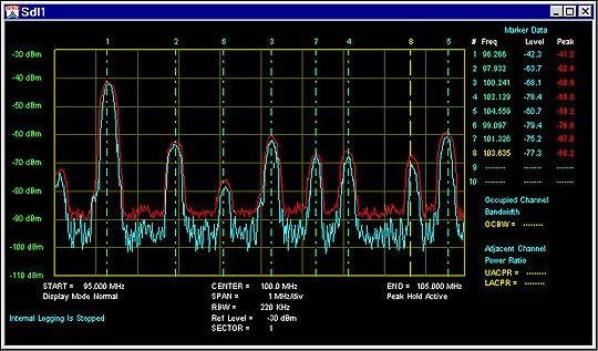
LPT-2250 Spectrum Analyzer

                                                      Table of Contents

1.0 GENERAL DESCRIPTION AND FEATURES.....................................................................................3

2.0 USAGE PRECAUTIONS AND RECOMMENDATIONS .....................................................................4

3.0 SETUP AND USE ................................................................................................................................6

4.0 SYSTEM ADJUSTMENTS ................................................................................................................12

5.0 SYSTEM BLOCK DIAGRAM ............................................................................................................13

APPENDIX 1 - CHARACTERISTICS ......................................................................................................14

APPENDIX 2 - REMOTE OPERATION...................................................................................................15

   Due to continuous improvements in the LPT-2250 Spectrum Analyzer, information
             contained in this Manual is subject to change without notice.
                      Contact LP Technologies, Inc., for revisions and corrections.

                                                  LP Technologies, Inc.
                                                  1919 N. Amidon, Suite 216
                                                   Wichita, KS 67203 USA

                                                  Telephone - 316.831.9696
                                                        Fax - 316.831.9692

                                                E-mail - support@lptech.com
                                                Web - http://www.lptech.com

Document # 070-1500-0001, Rev E                                                                                                    Page 2
LPT-2250 Spectrum Analyzer
1.0 General Description and Features
The LPT-2250 is a fully synthesized spectrum analyzer with large easy to read displays and easy to use
controls. The LPT-2250 is a measurement instrument capable of monitoring radio frequency (RF)
signals in the range of over 1 GHz to measure frequency, signal level, modulation and other signal
characteristics. The LPT-2250 is designed for minimal set-up and adjustment.
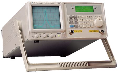
Figure 1 - LPT-2250 Front Panel
Item Description
1 Cathode Ray Tube (CRT) Display, 8 x 10 graticule, 5 inch
2 Liquid Crystal Display (LCD), 4 line x 20 character
3 Keypad, field selection and data entry
4 Spinner, field selection and data change
5 RF Input, Coaxial, Type N Female
6 Tracking Generator Output, Coaxial, Type N Female (optional)
7 Switch, Power ON / OFF
8 Adjustment, CRT Trace Rotation, potentiometer
9 Control Knob, Volume (optional demod receiver)
10 Phone Jack, head set output, (optional demod receiver)
11 Control Knob, CRT Focus
12 Adjustment, CRT Y-axis position, potentiometer
13 Control Knob, CRT Intensity
Document # 070-1500-0001, Rev E Page 3LPT-2250 Spectrum Analyzer
Figure 2 - LPT-2250 Rear Panel
Item Description
14 Panel Label, Usage Warning
15 External Frequency Reference Input, BNC (optional)
16 Connector, DB9, Female, RS-232
17 Panel Label, Serial Number
18 Cooling Fan Vent
19 Adjustment, CRT Trace Rotation, potentiometer
20 Adjustment, Internal Frequency Reference , potentiometer
21 Adjustment, LCD Contrast, potentiometer
22 Panel Label, Input Voltage
23 AC Input, Connector, Voltage Select and Fuse
2.0 Usage Precautions and Recommendations
The following precautions are recommended to insure your safety and to provide the best condition of
the LPT-2250.
1) Safety Terms and Symbols
The following terms and symbols may appear in this manual:
! WARNING This statement identifies conditions or practices that could result in injury or death.
! CAUTION This statement identifies conditions or practices that could result in damage to this
product or other property.
Document # 070-1500-0001, Rev E Page 4LPT-2250 Spectrum Analyzer
The following terms and symbols may appear on the instrument:
2 !
DANGER ATTENTION Protective
High Voltage Refer to Manual Ground Terminal
2) Use and Wear
! CAUTION
· Do not exceed +30 dBm into the RF INPUT or +30 dBm reverse power into the TG OUTPUT.
· Do not place any heavy object on the instrument.
· Avoid severe impacts or rough handling that could damage the LPT-2250.
· Use electrostatic discharge precautions while handling and making connections to the LPT-2250.
· Do not place wires into the connectors of the LPT-2250, only mating connectors and adapters.
· Do not block or obstruct cooling fan vent opening on side panels or on the rear panel of unit.
3) Disassembly of the Instrument
· Do not disassemble the instrument; refer the instrument to a factory approved service facility only.
4) AC Power Input
! CAUTION
· AC input should be within the range of selected line voltage +/- 10%.
· Insure the correct fuse is installed prior to applying voltage for the first time -
90 V ~ 132 VAC input : T 1.0A / 250V
198 ~ 250 VAC input : T0.5A / 250V
· Check the line voltage setting on the rear panel. If the line voltage does not match input voltage, change as
follows:
a) Remove AC Power Cord;
b) Open cover of AC socket with flat blade screwdriver;
c) Remove selector Cam Drum and rotate to the correct voltage selection
d) Replace Cam Drum.
5) Grounding
! WARNING
· To avoid electrical shock, the power cord protective grounding conductor must be connected to earth ground.
6) Fuse Replacement
! WARNING
· For continued fire protection, replace the fuse with the specified type and rating only.
· Disconnect power cord before replacing fuse.
· If the fuse is blown, there is something wrong with the instrument. Repair the cause of fault before replacing fuse.
7) Cleaning
· Disconnect AC Power Cord from the instrument before cleaning.
· Use a soft cloth dampened in a solution of mild detergent and water. Do not spray any liquid into the unit.
· Do not use chemicals or cleaners containing benzene, toluene, xylene, acetone or other harsh chemicals.
8) Operating Environment
· The following conditions are recommended for optimum use of the instrument -
Indoor Use Altitude < 2000 m Temperature 18° to 28° C Relative Humidity < 90%
Dust Free No direct sunlight No strong magnetic fields
· Installation Category: II
· Pollution degree: 2
9) Storage Environment
· The following conditions are recommended for optimum storage of the instrument -
Indoor Temperature 18° to 28° C Relative Humidity < 20%
Document # 070-1500-0001, Rev E Page 5LPT-2250 Spectrum Analyzer
3.0 Setup and Use
General Description
The LPT-2250 is a digitally synthesized spectrum analyzer capable of monitoring and displaying RF
signal characteristics over a frequency bandwidth of more than 1 GHz. The RF input is used to connect
to the device under test, or to an external circuit or antenna. The characteristic frequency and level of
the signals received are detected and displayed on the CRT.
The LPT-2250 may be configured with an optional tracking generator for stimulus / response
measurements of RF systems and components.
The LPT-2250 may be configured with an optional power meter for measuring RF power levels in watts
or dBm scales.
The LPT-2250 may be configured with an optional demodulation receiver for listening to AM and FM
signals.
Operation Figure 3 - Spectrum Display
Figure 3 shows a typical spectrum display. This example shows the
settings for a 100 MHz center frequency, a 1 MHz / division span and a
reference level of -10 dBm. The 8 by 10 division display indicates RF
level on the vertical or y-axis, and frequency on the horizontal or x-
axis.
The reference level is the top line on the screen, and each vertical
division down represents 10 dB. The center frequency is located at the
center grid position of the display, and each division across the display
represents 1 MHz.
Use
The settings and control for the LPT-2250 are easily accessed from the
keypad. The left column of keys are the field selections for Center Frequency (CENTER), Span
(SPAN) and Reference Level (REF LVL). Pressing one of these keys selects the corresponding setting
and screen edit field. The BLUE alternate function key is used to access the functions identified by the
blue text above the respective key. For instance, pressing BLUE followed by MEMORY selects the
TRACE functions.
The following table contains a list of the various data fields that may be controlled within the LPT-2250,
the selection for the field and the means to change or enter data into the field.
Table 1 - Data field selection and entry.
Field Selection Key Data Entry
Center Frequency CENTER 0-9, "." to directly enter a value;
ç and è SPINNER to scroll
ENTER or MHz to complete
Frequency Span SPAN SPINNER to scroll
Reference Level REF LVL SPINNER to scroll
Markers MARK SPINNER to select #1 or #2;
è to edit selected marker;
ENTER or MHz to complete
Document # 070-1500-0001, Rev E Page 6LPT-2250 Spectrum Analyzer
Field Selection Key Data Entry
Delta Marker DMARK DMARK to select Delta mode;
MARK to end Delta Mode
Memory Storage / Recall MEMORY SPINNER select Recall or Save;
è to edit Recall / Save number;
SPINNER scrolls numbers;
ENTER to complete
Resolution Bandwidth RBW ç and è SPINNER to scroll
(SPAN OF 0 Hz / div ONLY)
Demodulation (Optional Receiver) BLUE , DEMOD SPINNER to select demod type
Power Meter (Optional) BLUE , PWR MTR SPINNER selects change line;
ç or è to select an item;
SPINNER to scroll
Tracking Generator (Optional) BLUE , TRK GEN SPINNER selects change line;
ç or è to select an item;
SPINNER to scroll
Marker to Peak BLUE , PK > MKR No data to enter
Marker to Center Frequency BLUE , MKR > CF No data to enter
Trace Functions BLUE , TRACE SPINNER select trace item;
ç or è change value or turn
function ON / OFF
Setup Functions BLUE , SETUP SPINNER select setup item;
ç or è change value or turn
function ON / OFF
CENTER FREQ
This field is the value for the frequency located at the mid-point (center screen) of the selected span.
This frequency value may be changed by entering the digits, decimal point, followed by the ENTER or
MHz key, or the ç and è keys can select a digit to increment or decrement using the SPINNER.
The range of valid entries is 0.010 MHz to 1150.000 MHz. Setting the Center Frequency may change
the Span field if the span must be lowered to include the desired frequency. For example, if the Span
is set to 100 MHz/div and the Center Frequency is changed to 50 MHz, the span will change from 100
MHz/div to 10 MHz/div.
SPAN
This field is the value for the frequency range covered by the LPT-2250 as it sweeps its receiver. This
span value may be changed by the SPINNER to roll through the list of valid spans.
The range of valid entries is 2 kHz / division through 100 MHz / division plus zero span (0 Hz / div).
Setting the Span may change the Center Frequency field if the frequency must be increased to include
the desired Span. For example, if the Center Frequency is 25 MHz and the Span is changed from 5
MHz/div to 10 MHz/div, the Center Frequency will change to 50 MHz.
REF LVL
This field is the value the top of screen indication (RF level) for the received input signal. This
reference level value may be changed by the rotating the SPINNER to scroll through the list of valid
reference levels.
The range of valid entries is +20 dBm to -30 dBm in 10 dB steps.
Document # 070-1500-0001, Rev E Page 7LPT-2250 Spectrum Analyzer RBW This field sets the Resolution Bandwidth of the unit for Zero Span (0 Hz / div) mode (see Span operation above). The field can only be accessed while the Span is set to Zero Span. When the span changes to any selection other than Zero-Span, the RBW shown will be the preset value for the given Span. This RBW value may be changed by the rotating the SPINNER to scroll through the list of valid RBWs. MARKERS The LPT-2250 supports 2 markers. To access the marker screen, press the MRK key. Displayed will be 2 marker frequencies. Accessing the marker frequency fields is performed through the left column of numbers. Cursor to the left most position, then use the SPINNER to switch between marker 1 and marker 2. Pressing ENTER will also switch between the 2 marker fields. The frequency value may be changed by entering the digits, decimal point, followed by the ENTER key, or the ç and è keys can select a digit within a marker to increment or decrement by using the SPINNER. The valid range of entries is 0.000 MHz to 1150.000 MHz. A marker will appear on the CRT when the marker frequency selected falls within the range of frequencies defined by the main screen Center Frequency and Span. For example, if the center frequency selected is 100.000 MHz and the span is 1 MHz per division, a marker will appear on the screen if the marker frequency is anywhere between 95 MHz and 105 MHz. When the marker is displayed on the CRT, the signal level at the location of the marker will be displayed to the right of the marker frequency. This level will continuously update while in the marker screen. If the marker frequency is outside the range of frequencies for a given Center Frequency and Span, a message will indicate its status. If the marker frequency is too high to be displayed on the CRT, instead of the marker level, “Off (high)” will be displayed. If the marker frequency is too low, then “Off (low)” will be displayed. If the Markers are disabled, then “OFF” is displayed. To disable the markers, simply press the Marker key while in the markers sub-screen. If the markers are enabled, their position on the CRT will be updated on each Center Frequency change and each Span change. If a Center Frequency or Span is selected such that the marker moves off the CRT screen, they will be off until the parameter is changed to allow the marker to re-appear. The resolution of the marker on the screen is based on the span selected. There are 50 positions between major divisions on the CRT that a marker can be moved to. In the 100 MHz/div Span, for example, every 2 MHz will move the marker 1 position. On the outside edges of the trace, however, the maximum and minimum marker positions are considered out of range. PK->MKR This is a peak search function. Using marker 1, the LPT-2250 begins at the current marker 1 frequency and scans for a peak. When a peak is found in the trace, the marker frequency is updated to show the frequency of the signal and the level of the peak is also displayed. If no peak is found (that is greater in frequency than the current marker position), the marker stops at the end of the trace. Another press of the PK>MKR key will start a new search from the frequency point at the left-most edge of the span. If the marker is not active, it will be activated and a new search will begin from the frequency point at the left-most edge of the span. If the marker is active but the bottom half of the LCD display does not show the marker, the peak function will still complete and the marker on the CRT can be viewed. DELTA MARKERS The delta marker function is similar to the marker function. To access the marker screen, press the DMKR key. In this function marker 1 is used as the reference marker level and the marker 2 level is level difference between marker 1 and marker 2. Document # 070-1500-0001, Rev E Page 8
LPT-2250 Spectrum Analyzer

MKR->CF
This function moves the Center Frequency to the current Marker 1 frequency. This will occur even if the
marker is OFF. The span may be adjusted as required for the Center Frequency. It has no effect if the
current span selection is zero span.
TRACE
The TRACE key provides access to the Peak Hold, Average, and Freeze features of the LPT-2250.
These items are shown on the bottom half of the LCD display. By scrolling, all three items can be
accessed.
The Max Hold Function, when enabled, will maintain a trace showing the maximum signal received for
each point in the trace. It can be reset by disabling the function followed by re-enabling. Enabling this
feature will disable the Averaging feature if averaging was on. Markers may be used with the peak hold
function when not in zero span.
The Average Function, when enabled, shows a field showing the number of traces being used for
averaging. The selection can be changed with the ç and è keys. The valid selections are: “Off”,
2,4,8,16, and 32 traces. Enabling this feature will disable the Peak Hold function if Peak Hold was on.
Markers may be used with averaging when not in zero span.
The Freeze Function, when enabled, will freeze the CRT trace with no subsequent updates to the
screen. Updates will resume on the first key press after enabling the Freeze function.

MEMORY OPERATIONS: SAVE / RECALL
The save and recall functions are accessed by pressing the MEMORY key. The bottom half of the
screen shows one line for saving and one line for recalling up to 10 setups.
The “Recall” field provides the user with the ability to recall up to 10 different configurations of the LPT-
2250 including main screen fields, markers, tracking generator fields, and the power meter fields. To
recall a new set of parameters, press the è key to move the cursor to the load number field. Then use
the SPINNER to change the number from 1 to 10. While the cursor is on that field, pressing the
ENTER key will load the current state of the LPT-2250 with the loaded parameters.
The “Save” field provides the user with the ability to save up to 10 configurations of the LPT-2250
including the main screen fields, markers, tracking generator fields, and the power meter fields. To save
the current state of the unit, press the è key to move the cursor to the save number field. Then use the
SPINNER to change the number from 1 to 10. While the cursor is on that field, pressing the ENTER
key will save the current state of the LPT-2250 into that storage location.
SETUP SCREEN
The setup screen provides access to various parameters. The setup screen functions are accessed by
pressing the SHIFT RBW key. The trace will stop updating while in the setup screen. The parameters
are accessible using the SPINNER. The following identifies the various parameters:
          1. CAL Signal
          The “CAL Signal” provides access to an internal amplitude calibrator signal of 80MHz. Pressing
          the è key toggles the reference signal between “Off” and “On”.
          2. Option Report
          The “Opt Report” provides access to the current configuration of the LPT-2250 including
          optional hardware that is installed. Pressing the è key displays a screen showing Software
          Version (SW), Firmware Configuration (FW), Tracking Generator Configuration (TG, where “N”
          means option not installed), Receiver (R), Power Meter (PM) and Reference Signal (REF). The
          “TG”, "R" and "PM" labels will be followed by “N” if the option is not installed. The “REF” label is
          followed by two fields that identify the status of a 10 MHz system frequency reference signal
          that can be applied to the unit. The first field will display “STD” for standard and “IMP” for

Document # 070-1500-0001, Rev E                                                                   Page 9
LPT-2250 Spectrum Analyzer
improved. The second field will display “INT” for internal 10MHz reference, or “EXT” for external
10MHz reference.
3. Test All
The “Test all” field automatically checks the LO statuses of LO1, LO2, and LO3. If all three LO’s
are locked, the “Locked” is displayed. If one of the three is unlocked, then “Unlocked” is
displayed.
4. LO1 Status
This displays the status of LO1. An internal status is monitored to determine if it is “Locked” or
“Unlocked” with the result being displayed.
5. LO2 Status
This displays the status of LO2. An internal status is monitored to determine if it is “Locked” or
“Unlocked” with the result being displayed.
6. LO3 Status
This displays the status of LO3. An internal status is monitored to determine if it is “Locked” or
“Unlocked” with the result being displayed.
7. Units
This controls the units displayed for the optional power meter. The selections are “mW” and
“dBm”.
DEMOD (Optional)
The LPT-2250 can be optionally configured to perform FM and AM demodulation. To access this
feature, press the SHIFT DEMOD key. The bottom half of the LCD display will show the current
demodulation selection that can be changed with the SPINNER, rotating counter-clockwise through
OFF, AM, Wide, Medium, Narrow. Zero span is activated when DEMOD is activated. The
demodulation audio will be routed to the speaker or the front panel audio jack. There are default RBWs
associated with the various demodulation modes. For FM-Wide, FM-Medium, and FM-Narrow, the
default RBW is 220 kHz. For AM demodulation, the default RBW is 30 kHz. For FM demodulation
modes, the RBW may be changed between 220 kHz and 4 MHz. For AM demodulation modes, the
RBW may be changed between 3 kHz, 30 kHz, 220 kHz, and 4 MHz. The default RBW is restored
each time SHIFT DEMOD is pressed. Therefore, the DEMOD value(AM, WIDE-FM, MEDIUM-FM,
NARROW-FM) should be selected first, then the RBW value.
TRACKING GENERATOR (Optional)
The optional tracking generator screen is accessed through the SHIFT TRK GEN key. Upon entering
the screen, 3 fields are displayed. The “TRK GEN” label displays the status of the tracking generator.
Pressing the ç key will turn the tracking generator on and off if the option is installed. Pressing the è
key will move the cursor to the NORMALIZE field. Pressing the è key once more will activates the
NORMALIZE function. Using the SPINNER allows the user to access the second line. For
convenience, pressing the ENTER key will move the cursor through the different fields for easier
operation.
The second line displays the tracking generator level and frequency offset (no label for frequency
offset). Both fields can be accessed by pressing the ç and è keys. To change the fields, use the
SPINNER. The numbers will scroll through the valid range of values.
The normalize function allows the user to calibrate out the gains and losses in the cables or other units
under test. To use the normalize function, connect the equipment to the tracking generator output port
and the spectrum analyzer input port. Following a normalize, the LPT-2250 will factor out the measured
variances. When the Span or Center Frequency fields are changed, the normalize will be reset and
should be run again.
POWER METER (Optional)
Document # 070-1500-0001, Rev E Page 10LPT-2250 Spectrum Analyzer To access the power meter in the LPT-2250, press the SHIFT PWR MTR. If the power meter option is not installed, the display will not change. If the power meter option is installed, the bottom half of the screen will show the power level in mW or dBm based on the units selected in the setup screen. The range field will allow the user to change the range (2 mW, 20 mW, 200 mW, 2 W) or select “AUTO” range to let the LPT-2250 select a valid range. The 4-digit frequency field specifies the frequency of the signal to measure. This field is independent of the Center Frequency field as it is only used for the power meter. The “ZERO” function will zero the power meter in all ranges required. This should be performed before taking initial readings. When performing a zero function, there should be no signal source connected to the LPT-2250. The power meter readings will continuously update as long as the power meter is active. A power reading of “-∞” indicates a value of 0 mW in dBm units. SAVING POWER-UP SYSTEM PARAMETERS Power-up information will be saved any time the setup screen is exited. To access the setup screen, press the SHIFT SETUP key. To exit the setup screen, press the ENTER key. When exiting, the fields will be saved to a non-volatile storage device. The information saved includes the Center Frequency, Span, and Reference Level fields, the marker frequencies, the power meter fields, and the Tracking Generator fields. Document # 070-1500-0001, Rev E Page 11
LPT-2250 Spectrum Analyzer

4.0 System Adjustments

AC Input Selector and Fuse. See Figure 2, Rear Panel, Item 23. See section 2, page 3 for details of
setting the proper voltage and fuse.

Note: X-Position, Y-Position, Trace Rotation may be affect by the orientation of the unit relative to the
earth’s or other local magnetic field sources. The display will shift in apparent position, but the marker
accuracy will not be affected. Simply readjust the X-position, Y-position and Trace rotation when the
instrument’s position is changed, if it is desired to maintain the display in the precise orientation.

Intensity. See Figure 1, Front Panel, Item 13. This is a knob adjustment which sets the trace
brightness for the signal and marker display on the CRT.

Focus. See Figure 1, Front Panel, Item 11. This is a knob adjustment that sets the focus of the trace
and marker displayed on the CRT.

Volume. See Figure 1, Front Panel, Item 9. This is a knob adjustment for the optional receiver volume
when the receiver is activated.

Y-Position. See Figure 1, Front Panel, Item 12. This is a flat blade screwdriver adjustment for setting
the horizontal position of the displayed trace and marker. Activate the marker function at the current
center frequency(see section 3, page 8). Adjust the Y-Position so that the bottom of the marker just
touches the bottom line of the CRT graticule.

X-Position. See Figure 1, Front Panel, Item 8. This is a flat blade screwdriver adjustment for setting
the horizontal position of the displayed trace and marker. Activate the marker function at the current
center frequency(see section 3, page 8). Adjust the X-Position so that the marker is positioned on top
of the center vertical graticule. Adjust trace rotation, if necessary. The Trace Rotation Adjustment may
need to be performed at the same time.

LCD Contrast. See Figure 2, Rear Panel, Item 21. This is a flat blade screwdriver adjustment for
setting the contrast of the 4-Line LCD display. Adjust for best contrast at the viewing angle you prefer.

Frequency. See Figure 2, Rear Panel, Item 20. This is a flat blade screwdriver adjustment for setting
the reference oscillator frequency for the entire system. If an optional Higher Stability Option(HSO) is
installed, this adjustment set the frequency of the 10MHZ TCXO. Check that the internal Calibrator
signal is off(see section 3). Set the unit to a convenient frequency where the customer has a known
accurate frequency standard. Set the input Reference level appropriately for the strength of the
external calibration signal. Set the span to 2kHz/div(20kHz total span). Allow the LPT-2250 to
stabilize for 15 minutes from the time power was first applied. Connect the external standard
frequency. Adjust the FREQ adjustment on the rear panel until the standard frequency is displayed in
the center of the display.

Trace Rotation. See Figure 2, Rear Panel, Item 19. Activate the marker function at the current center
frequency(see section 3, page 8). Adjust the X-Position so that the marker is positioned on top of the
center vertical graticule. Adjust Trace Rotation, so that the vertical marker is parallel with the center
vertical graticule line..

Document # 070-1500-0001, Rev E                                                                 Page 12
LPT-2250 Spectrum Analyzer
5.0 System Block Diagram
This is a functional block diagram, with certain details omitted and simplified for clarity.
A14 A15 S2
S1
A16
3kHz
LO4 mixer SW SPDT
SW SPDT
A17
30kHz
A1 A2 A3 A4 A5 A6 A7 A8 A9 A10 A11 A12 A13 S4 A20
S3 A21
J1
LOG
0/10/20/30/40/50 dB A18 A20 LOWPASS
RF IN LIMITER PWR DIVIDER PWR COMBINER MIXER BANDPASS MIXER BANDPASS MIXER SW SP3T 220kHz SW SP3T
A22
A24 A25 A26 A27 A28 A29 ADC
A23 A
D
C
A19
4MHz
LO1 LO2 LO3
det small CALIBRATOR
PLL PLL PLL
Power Meter Option
A30 A31
80MHZ DDS
A32
PLL
TCXO-10MHz
Higher Stability Option
A33 A34
A37 A38 A39 A40 A41 A42 A43 Micro Processor
J2 A35 A36
A44 DAC P1
TG OUT Limiter 5
0/10/20/30/40/50 dB TRACK OFFSET 9
BANDPASS BANDPASS 4
Pwr Divider MIXER MIXER MIXER ATTEN DAC 8
A45 3
7
2
A46 DAC 6
1
det small Trackign Generator DAC REMOTE CONTROL RS232
Option
REMOTE CONTROL RS232
DISPLAY
Vert.
Horiz.
Blanking
JST-6
CRT/DRIVE SECTION CRT CONTROL/
POWER SUPPLY
3.5mm
Stereo
Jack
Audio J3 AM/FM RECEIVER OPTION
Out
SPEAKER
FRONT PANEL
Document # 070-1500-0001, Rev E Page 13LPT-2250 Spectrum Analyzer Appendix 1 - Characteristics Characteristics are for reference purposes only. Contact LP Technologies for the latest characteristics and specifications. Frequency · Frequency range 10 MHz through 1 GHz, usable 30 kHz to 1.15 GHz · Frequency resolution 1 kHz · Span range 2 kHz to100 MHz / div in 1-2-5 sequence plus Zero Span · Resolution bandwidth 3 kHz, 30 kHz, 220 kHz, 4 MHz · Video bandwidth 1 kHz nominal · Time base stability +/-10 ppm Amplitude · Input level (maximum) +20 dBm (max. atten.), protected to +30 dBm for 1 minute · Display level flatness +/-1.5 dB @ 10 MHz / div · Display range 75 dB usable · Ref. Level range -30 dBm to +20 dBm Other · Power 100 to 130 VAC, 210 to 240 VAC (selectable), Less than 100 VA · RF input Type N, Female · Tracking Generator output Type N, Female · External Frequency Reference In BNC Female · RS-232 input / output Computer Interface, DB-9 Functions · Marker, Marker Delta, Marker to Peak, Marker to Center Frequency · Trace Average, Trace Max Hold, Trace Freeze · Internal Reference Signal, Self-test · System Setup and Recall Options · Power Meter · Tracking Generator · Demodulation Receiver · High-Stability Oscillator / External Reference Input · Remote Control Software Document # 070-1500-0001, Rev E Page 14
LPT-2250 Spectrum Analyzer

Appendix 2 - Remote Operation
With remote operation, the LPT-2250 is capable of communicating with a computer over the RS-232
port. No setup is required on the LPT-2250 to enable the remote interface. The LPT-2250 will monitor
the RS-232 port and respond when a PC is connected.
The PC applications are designed to run on Windows® NT, Windows® 95, or Windows® 98. The serial
port used is selectable and the port setups are handled automatically by the application. The cable
should be a straight through RS-232 cable (not a NULL modem).
Two programs are available for use with the LPT-2250. The "standard" program provided with the LPT-
2250, "SDLMON.EXE" provides display of the spectrum trace, saving the trace and printing of the trace,
but no computer control of the LPT-2250 settings. The optional program "SDL.EXE" provides the same
functions as the standard SDLMON.EXE, plus allows you to control the unit from the computer.

SDL.EXE
SDL.EXE provides a simple method to use the LPT-2250 with a computer, both for display and control.
To install, simply create a directory on your computer for saving SDL.EXE, and copy the programs on
the diskette provided into the directory.
To run the program, double-click the SDL icon.
The picture to the right shows the SDL screen. Standard Windows ® functions are provided for use,
such as file open, save, save as, etc., and are not described in detail here.

Eleven buttons shown here, and on the right end of the tool bar, provide the bulk of the display control
for the LPT-2250. Initial operation with any buttons prompts the operator for a key (number) that is
required to use the computer with the LPT-2250. This number is unique to each serial numbered LPT-
2250. Once entered, the user should not be required to re-enter the key again. If the key is lost,
contact LP Technologies Customer Service for assistance.

The function and use of these are --

Document # 070-1500-0001, Rev E                                                             Page 15
LPT-2250 Spectrum Analyzer

START            This button begins continuous display of the LPT-2250 spectrum traces on the computer
                 display. The display is updated at a rate of approximately 2 to 3 traces per second,
                 depending upon computer speed.
STOP             This button halts the continuous display of LPT-2250 spectrum traces.
1 SHOT           This button acquires one trace from the LPT-2250, displays the trace, and halts.
AVG              This button averages the displayed signal. This can reduce noise or other fluctuations in
                 a random signal, giving a more accurate measurement in some cases.
è (SEND)         This button brings up a window to allow the user to send data to the LPT-2250 for --
                                  CENTER Frequency, SPAN, REF LVL and RBW
                 The change of data may be made while the unit is operating in continuous mode, but the
                 display update will halt until the entry process is completed (click OK). If mutually
                 exclusive entries are made (SPAN that violates CENTER limits), the LPT-2250 will not
                  accept the conditions that are invalid.
PORT             This button brings up a setup window to allow the user to select which communication
                 port of the computer to use for the LPT-2250 (COM1, COM2, COM3, COM4).
ü (CHECK)        This button sends a test message to the LPT-2250 at the selected port and awaits a
                 correct response.      If the correct response is received, a communications link is
                 established and valid operation can begin. If there is no response, or an invalid response
                 is received, an error message is displayed. This is provided to assist in verifying the
                 correct communication port is selected and is functioning properly.

| | (MARKERS) This button brings up a setup window to allow the user to enter the frequency of 10
                 markers. The markers are displayed at the position entered, and are color-coded and
                 dashed differently for easy identification.     The signal level at the respective marker
                 position is displayed below and to the left of the graticule area. Access the setup screen
                 by using the Marker Icon located on the SDL toolbar. They can be activated manually by
                 setting the frequency in the edit box on the marker setup screen. Click the OK button to
                 activate. There are additional special features that are activated by the check boxes
                 located on the marker setup screen next to the edit box of each marker. They are Peak,
                 and the Next Right, and Next Left check boxes. These features are automatic and do not
                 require a frequency value to be entered. Peak will find the strongest signal in the current
                 sweep. Next right and next left can be used to locate the next peak right or left of that
                 marker’s position. If the marker has not been activated, it will find the first peak from the
                 left edge of the current sweep in the direction of the arrow. An additional feature can be
                 used by clicking both the peak check box and either next left or next right check box. This
                 feature will find the strongest peak then set the marker to the first peak right or left of the
                 strongest peak. Marker values are located on the right side of the sweep screen and they
                 report in real time, the frequency, true level, and peak level of that marker. Note: peak
                 level is only displayed when the peak hold is active. The marker values are color coded
                 to match the sweep trace. The frequency and marker number is in green, except the

Document # 070-1500-0001, Rev E                                                                    Page 16
LPT-2250 Spectrum Analyzer
current marker (normally the last marker set) which is in yellow. If a marker is moved off
the sweep screen, the values will again show dashes indicating the marker is out of
range of the current sweep.
OCBW
ACPR Occupied Channel BandWidth: One toolbar Icon activates the setup screen for both of
these functions. Entering a non zero frequency in the Channel Width field will activate
this function. A realtime output of this function is displayed on the right side of the Sweep
screen just below the marker values. If there is no current marker, (the number at the
bottom of the setup screen is zero) one will be automatically activated for you and set to
the strongest signal in the current sweep. If markers are active, this number reflects the
current marker and is the one the displayed data is using. If you wish to use another,
changing the number will switch your choice to be the current marker and the displayed
reading will reflect that marker location. If a channel width is selected that exceeds the
current sweep's span, the channel width will be adjusted and the new value will be
displayed below the data display.
Adjacent Channel Power Ratio: This function operates the same as OCBW and is
displayed just below OCBW on the right side of the screen. There are 3 fields that are
entered. (1) Signal Channel Width. (2) Adjacent Channel Width. and (3) Adjacent
Channel Offset. Setting any of these to "0" will disable the function. If the offset exceeds
the current span setting, the function will inform you of the problem and will be disabled.
The other 2 will readjust and notify you of the changes. Two items of data are displayed.
UACPR (Upper Adjacent Channel Power Ratio) and LACPR (Lower Adjacent Channel
Power Ratio).
Tracking Generator
The Tracking Generator option for the LPT-1750 provides a RF generator output that
sweeps with the analyzer. The output range is adjustable from 0 dBm to –50 dBm. The
frequency may be offset from the sweep frequency by +/- 99 kHz. Pressing the “TRACK”
icon located in the SDL toolbar accesses the optional tracking generator screen. Upon
entering the screen, 4 items are displayed. The ‘Generator On’ check box is used to turn
the Tracking Generator on or off. Click the box to the right of the label to control the
generator. A check mark in the box will turn the generator on when the ‘OK’ button is
pressed.
Document # 070-1500-0001, Rev E Page 17LPT-2250 Spectrum Analyzer
The Normalize is used to level the generator output. Clicking on the check box to the
right of the Normalize label will set the function to on. Clicking again will clear the check
mark and Normalizing will not occur when ‘OK’ is pressed. Normalizing is a process that
compensates for unflatness in the system. To normalize a coaxial cable, connect the RF
OUT to the RF IN with the desired coax. Select the center frequency and span as
desired.
Select the Normalize field and click the ‘OK’ button. The LPT-2250 will measure the
response and correct point by point for flatness. These settings will remain active until a
new center frequency or a new span is selected. The next two boxes allow the user to set
the generator level and offset frequency. Valid generator levels are from 0 dBm to –59
dBm in 1 dB steps. An entry out of range will be automatically set to the closest valid
range. If an entry of –65 dBm was entered, the generator will be set to –50 dBm and if an
entry greater than 0 dBm is entered, the level will be set to 0 dBm. Generator offset is
used to offset the generator sweep frequency by +/- 99 kHz in 1 kHz steps. Both of these
fields are entered by clicking on the data box and entering the desired setting from the
keyboard. Only the numeric data need be entered. None of the above functions have any
effect until the ‘OK’ button is pressed. If the ‘Cancel’ is pressed, none of the previous
settings will change. Note: Normalize will take several seconds to complete after the ‘OK’
was pressed.
Peak Hold Peak level is displayed with real time current signal level when the peak hold is active.
Document # 070-1500-0001, Rev E Page 18You can also read