BRP Series Basic Rectifier Protection System Installation, Operation and Service Manual - DynAmp
←
→
Page content transcription
If your browser does not render page correctly, please read the page content below
BRP Series

              Basic Rectifier Protection System

         Installation, Operation and Service Manual

                            Manual Item No. 044423

                                             Rev. M

DynAmp, LLC     3735 Gantz Road                Phone +1 614.871.6900   www.dynamp.com
                Grove City, Ohio 43123 USA     Fax +1 614.871.6910     help@dynamp.com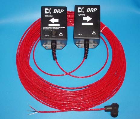
Installation, Operation and Service Manual                         BRP Series

                                This Page is Intentionally Blank

© 2020 DynAmp, LLC                                                 Page ii
044423 M
Installation, Operation and Service Manual BRP Series
DynAmp, LLC WARRANTY
Items and components manufactured by DynAmp, LLC for permanent installation are warranted to be
free from defects in material and workmanship for a period ofr two (2) years from the date of shipment.
Items and components manufactured by DynAmp, LLC for portable and temporary use in more than
one location, are warranted to be free from defects in material and workmanship for a period of eighteen
(18) months from the date of shipment.
Extended warranties may be available for purchase for some products. Extended warranties are
provided on a serial number by serial number basis as noted on DynAmp’s original invoice and/or
packing list.
Items and components not manufactured and resold by DynAmp, LLC, are warranted by their
manufacturer.
Warranty repair shall be, at DynAmp’s option, in the form of repair or replacement of the defective items
or components. Concerning warranty repairs, DynAmp, LLC will be responsible for DynAmp provided
time, material and transportation costs (shipping or travel). Actual method of warranty repair / correction
will be determined by DynAmp, LLC at DynAmp’s sole option. Such warranty repair shall constitute a
fulfillment of all DynAmp, LLC liabilities in respect to said items and components. In no event shall
DynAmp, LLC be liable for consequential damages.
Information in this document is subject to change without notice.
© 2005, 2007, 2008, 2009, 2011, 2013, 2016, 2018, 2020 DynAmp, LLC. All rights reserved.
Reproduction in any manner whatsoever for purposes other than installation, operation pr service by the
purchaser or end user without written permission of DynAmp, LLC is strictly forbidden.
This manual is part of the complete set of product documentation that includes installation, operation, and
service instruction, drawings and test results. Users should evaluate the information in the context of the
complete set of product documentation and their particular applications. DynAmp, LLC assumes no liability
for any incidental, indirect, or consequential damages arising from the use of this documentation.
While all information presented is believed to be reliable and in accordance with accepted engineering
practices, DynAmp, LLC makes no warranties as to the completeness of the information.
All trademarks used in association with BRP are trademarks of DynAmp, LLC.
© 2020 DynAmp, LLC Page iii
044423 MInstallation, Operation and Service Manual BRP Series
This Page is Intentionally Blank
© 2020 DynAmp, LLC Page iv
044423 MInstallation, Operation and Service Manual BRP Series
Hazard Warning!
All installation, maintenance and service must be performed by qualified
technicians who are familiar with the warnings and instructions of this
manual.
Use of the equipment in a manner not specified by the manufacturer
can impair the protection provided within.
DynAmp does not assume liability for the customer’s failure to comply
GENERAL with the rules and requirements provided in this manual.
This equipment is mounted on current-carrying busbars that may be
energized at hazardous electric voltages during normal operation.
DynAmp recommends installation of BRP sensors on de-
energized busbar(s). The associated power rectifier should also be
locked out. If it is not possible to de-energize the busbar(s) during
installation, the user assumes all responsibility to ensure that adequate
procedures are followed to assure safety of personnel.
Ignoring the installation precautions and warnings can result in severe
HAZARDOUS personal injury or equipment damage.
VOLTAGE
To avoid the risk of electrical shock or fire, the safety instructions and
guidelines in this manual must be followed. The electrical
specifications must not be exceeded and the unit must be installed
according to directions provided.
Make sure sensors are installed with arrows pointing in the direction of
conventional current flow in the bus. If sensors must be replaced,
they should be replaced as a matched set.
SENSOR
INSTALLATION/
REPLACEMENT
Symbol Identification:
General definitions of safety symbols used on equipment and manual.
Caution/Warning: Refer to accompanying documents for instructions.
© 2020 DynAmp, LLC Page v
044423 MInstallation, Operation and Service Manual BRP Series
This Page is intentional Blank
© 2020 DynAmp, LLC Page vi
044423 MInstallation, Operation and Service Manual BRP Series
DynAmp, LLC Customer Support & Service Assistance
For further assistance, contact DynAmp, LLC Customer Support at:
Americas:
Telephone: +1 614.871.6900 Fax: +1 614.871.6910
8:00 AM to 5:00 PM USA Eastern Time
From first Sunday in November to second Sunday in March – 13:00 GMT to 22:00 GMT
From second Sunday in March to first Sunday in November – 12:00 GMT to 21:00 GMT
After Hours Critical Service Emergency:
Telephone: +1 614.871.6906
5:00 PM to 8:00 AM USA Eastern Time
From first Sunday in November to second Sunday in March – 22:00 GMT to 13:00 GMT
From second Sunday in March to first Sunday in November – 21:00 GMT to 12:00 GMT
Central e-mail:
help@dynamp.com
DynAmp web:
www.dynamp.com
© 2020 DynAmp, LLC Page vii
044423 MInstallation, Operation and Service Manual BRP Series
This Page is Intentionally Blank
© 2020 DynAmp, LLC Page viii
044423 MInstallation, Operation and Service Manual BRP Series
REVISION PAGE
Page Revision Reason For Revision Date
All NEW 04/05
All A Updated Manual per ECR 1256 adding option 11/05
information
16 B Updated table 5-2. 01/07
All C Updated per ECO 3177 04/07
7, 15, 17 D Updated per ECO 3178 01/08
15, 17 D1 Updated per additional findings – Trip Module terminals 05/08
to 7 & 8 and update dwgs 05B108865D / 83B108876C
Update per ECR 1437 – Specifications, Delete: 90°
7, 13, Connector Orientation (5-2), Instructions for Customer
03/09
17-18, 21 E Adjustment of Forward Trip setpoints (5-6), and delete
dwg 64A044455 from list.
3-5, 7-8 F ECO 3217 - Removed 3.5 and included in 3.2, Table 09/09
13-19, 23 4.1 Specifications, Section 6 Theory of Operation,
all Drawing List, PAR 10245 add Handling & Storage
section
23 G ECR 1440 – Insert Calibration Intervals 08/11
9 H ECR 1652 – Change isolation voltage 09/11
10,11,15, CAR 10150 – Revise Forward Trip Setpoint information
I 7/13
16, 18-22 and add table for customer use.
10,11,15,
J ECO-3292 eliminate BRP-PE option. 11/13
16, 18-22
ECR 2104 – Update Power handling in specifications,
6, 8, 19 K updated Figure 3.2 and drawing 84B108987, added 11/16
02A109534
19 L ECR 2190 – Add drawing 02B109594- 01/18
19, iii, vii, M ECO 3369 - Update drawing 83B108876 to Rev F. 08/20
ECO 3347 - Update general verbiage.
© 2020 DynAmp, LLC Page ix
044423 MInstallation, Operation and Service Manual BRP Series
This Page is Intentionally Blank
© 2020 DynAmp, LLC Page x
044423 MInstallation, Operation and Service Manual BRP Series TABLE OF CONTENTS Par. Title Page 1. SAFETY _________________________________________________________ 1 1.1 OVERVIEW ......................................................................................................................................1 2. HANDLING AND STORAGE __________________________________________ 3 3. DESCRIPTION ____________________________________________________ 5 3.1 APPLICATION ..................................................................................................................................5 3.2 SYSTEM COMPONENTS ................................................................................................................5 3.3 ENHANCED VERSION OF THE BRP...............................................................................................6 3.4 OPTIONAL COMPONENTS .............................................................................................................6 4. PRODUCT SPECIFICATIONS ________________________________________ 7 5. INSTALLATION ___________________________________________________ 9 5.1 HANDLING PRECAUTIONS ............................................................................................................9 5.2 INSTALLATION CONSIDERATIONS ...............................................................................................9 5.3 INSTALLATION OF SENSOR PAIR .................................................................................................9 5.4 TESTING THE STATUS OUTPUT .................................................................................................10 5.5 INSTALLING OPTIONAL SYSTEM COMPONENTS .....................................................................10 6. THEORY OF OPERATION __________________________________________ 13 6.1 CHARACTERISTICS OF A REVERSE TRIP EVENT .....................................................................13 6.2 HOW THE SENSOR PAIR WORKS ...............................................................................................13 6.3 NORMAL OPERATION – BASIC SENSOR PAIR ...........................................................................14 6.4 OUTPUT LATCHING TRIP MODULE ( OPTIONAL ) .....................................................................14 6.5 BRP-L NORMAL OPERATION .......................................................................................................14 7. SERVICE, PARTS, AND DOCUMENTATION ____________________________ 17 7.1 CALIBRATION INTERVALS ...........................................................................................................17 8. DRAWINGS _____________________________________________________ 19 © 2020 DynAmp, LLC Page xi 044423 M
Installation, Operation and Service Manual                                         BRP Series

FIGURES & TABLES
Figure / Table Title                                                               Page

Figure 3.1 Basic Sensor Pair                                                          5
Figure 3.2 IP67 Enclosure with +24V Power Supply, Trip Module & Mechanical Relay      6
Figure 6.2 Reverse Trip kA with Fixed Setpoint (Gauss)                               14

Table 4.1   BRP Specifications                                                        7
Table 4.1   BRP Specifications Continued                                              8
Table 6.1   BRP-L Output and LED Status                                              15
Table 8.1   Drawing List                                                             19

© 2020 DynAmp, LLC                                                                 Page xii
044423 M
Installation, Operation and Service Manual                                                    BRP Series

1. SAFETY

    1.1     OVERVIEW
        This equipment is mounted on current carrying busbars that are energized at hazardous
        electric voltages during normal operation. Ignoring the installation precautions and warnings
        can result in severe personal injury or equipment damage. The following are general
        guidelines that should be followed when installing, operating and servicing the BRP.
        Busbar should be de-energized with power locked out during installation of Sensor Pair.
        Qualified technicians must perform all installation, maintenance, and service of this product.
        Personnel performing the installation must be familiar with the warnings and instructions of
        this manual.
        Always follow all local and plant safety procedures.
        Units are not intrinsically safe. Do not place in explosive atmospheres.
        The sensors and cable assembly are rated IP67. This provides total protection of persons
        from touching voltage-carrying conductors or internal parts and protection from access of
        dust. IP67 also indicates that if the Sensor Pair and cable assembly are dipped into water
        (0.15 to 1 meter) under defined conditions of pressure and time, water will not enter in any
        harmful quantity. The sensors and cable assembly are NOT to be permanently submerged
        or used underwater.
        Use of the equipment in a manner not specified by the manufacturer can impair the protection
        provided.
        DynAmp does not assume liability for the customer’s failure to comply with the rules and
        requirements provided in this manual.

© 2020 DynAmp, LLC                                                                            Page 1
044423 M
Installation, Operation and Service Manual BRP Series
This Page is Intentionally Blank
© 2020 DynAmp, LLC Page 2
044423 MInstallation, Operation and Service Manual BRP Series
2. HANDLING AND STORAGE
DynAmp products are engineered and manufactured for use in industrial environments.
However, they contain sensitive electronic and mechanical components which may be
damaged and fail if not handled and stored properly. All products must be handled and stored
with the same care as any precision measurement instrument. Severe bumps or jolts may
damage internal parts and cause malfunction or premature failure. DynAmp products are
designed and assembled with conformal coating, shock mounting, and environmental seals,
when appropriate or when specified. However, this protection requires that the product must
be properly installed and operational before the protection is fully functional. Therefore,
adequate protection from humidity, shock, and temperature must be provided during handling
and storage prior to installation.
The handling and storage of equipment must be sufficient to meet the storage temperature
and humidity specifications of the product and to prevent any condensation or contact with
water or any other liquid. The storage location and container or crate must provide adequate
protection from precipitation (rain, snow, ice) and direct water contact. Adequate shelter must
be provided to prevent the accumulation of precipitation (rain, snow, ice) and water which can
lead to the deterioration or failure of shipping containers or crates and cause water ingress.
Storage in coastal or industrial areas subject to salt-laden or corrosive air or areas of wind-
driven sand or other abrasive dust must be adequate to prevent the deterioration or failure of
shipping containers or crates and cause ingress. Frequent inspection of storage areas and
storage containers or crates is required to ensure proper storage conditions are being
maintained.
If the shipping container or crate is opened and/or the equipment is removed for inspection
prior to installation, the equipment must be repackaged in the original undamaged container
or crate in the same manner as it was shipped to prevent environmental damage or placed in
a storage location that meets the required environmental and storage conditions.
General product storage temperature and humidity requirements:
Storage Temperature: -40 to 70°C
-40 to 158°F
Storage Humidity: Maximum 85%, non-condensing
DynAmp, LLC does not assume liability for the customer’s failure to comply with handling and
storage requirements.
For further assistance, contact DynAmp customer support.
© 2020 DynAmp, LLC Page 3
044423 MInstallation, Operation and Service Manual BRP Series
This Page is Intentionally Blank
© 2020 DynAmp, LLC Page 4
044423 MInstallation, Operation and Service Manual BRP Series
3. DESCRIPTION
3.1 APPLICATION
The Basic Rectifier Protection system (BRP) protects high-power DC rectifiers and their related
circuitry against reverse current conditions. For most applications, one BRP Sensor Pair is
used on each rectifier bus that feeds a common load.
3.2 SYSTEM COMPONENTS
The BRP consists of:
• One pair of open-loop Hall effect current sensors permanently wired together.
• Interconnection Cable assembly
• Hardware for mounting sensors directly on busbar
Figure 3.1
Basic Sensor Pair
The BRP provides one Status Output for reverse current. This fail-safe output indicates normal
rectifier condition (reverse current not present) with a binary “1” (+24V). In the event of reverse
current, the Status Output signal level changes instantaneously to a binary “0” (0V). The
minimum duration of a 0V reverse trip indication is 200 milliseconds. The Status Output will
change state when reverse current exceeds approximately 7.5kA. The Status Output may be
directly connected to a relay coil or to the signal input of a PLC or other electronics. The Status
Output is short-circuit/overcurrent protected and will source or sink up to 100mA at +24V.
The BRP requires an external, regulated +24Vdc power supply. Connection to the Input Power
and Status Output are made via the Interconnection Cable assembly included with the BRP
Sensor Pair.
© 2020 DynAmp, LLC Page 5
044423 MInstallation, Operation and Service Manual BRP Series
3.3 ENHANCED VERSION OF THE BRP
An enhanced version of the BRP is available:
BRP-L consists of:
• One pair of open-loop Hall effect current sensors permanently wired together
• Interconnection Cable assembly
• Hardware for mounting sensors directly on busbar
• Trip Module for latching reverse current alarm (latches the Status Output signal from
the Sensor Pair)
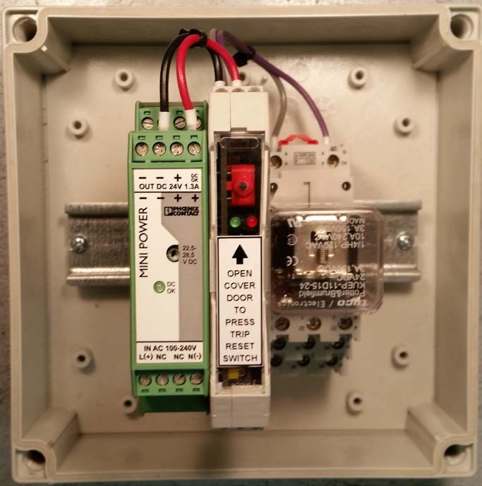
3.4 OPTIONAL COMPONENTS
The following components may be ordered with any BRP system :
• Mechanical relay with two “Form C” contacts, rated 3 Amps @ 150Vdc
• Power supply: 85-264 Vac, 90-350Vdc input range / +24Vdc @ 1A output
• IP67 enclosure with DIN rail, cable glands and wiring for trip module, relays and
power supply.
Figure 3.2
IP67 Enclosure with +24V Power Supply, Trip Module & Mechanical Relay
© 2020 DynAmp, LLC Page 6
044423 MInstallation, Operation and Service Manual BRP Series
4. PRODUCT SPECIFICATIONS
Table 4.1
BRP Specifications
BRP : Basic Rectifier Protection
Reverse Trip point -7.5kA ±2.5kA
Response time < 1mS
Signal Output Fail-safe Logic +24VDC 100mA max. drops to 0 VDC upon
reverse alarm returns to +24VDC 200mS after reverse current
event ends
Mains Power 22…26Vdc, 25mA,Installation, Operation and Service Manual BRP Series
Table 4.1
BRP Specifications Continued
OPTION SPECIFICATIONS
Optional Power Relay for Reverse or Over Current Alarms
( specially designed for reliable operation with higher power AC and DC loads )
Response time :Installation, Operation and Service Manual BRP Series
5. INSTALLATION
The BRP Sensor Pair is mounted on current-carrying busbar(s) that may be
energized at hazardous electric voltages during normal operation. DynAmp
recommends that installation and maintenance of BRP sensors be performed
only when associated busbar(s) are de-energized. The associated power rectifier
should also be locked out during installation or maintenance. The user assumes
all responsibility for implementation of adequate procedures and practices to
ensure safety of installation and maintenance personnel.
5.1 HANDLING PRECAUTIONS
Review plant safety regulations before installation.
The BRP Sensor Pair and Interconnection Cable assembly should be inspected for shipping
damage at the earliest opportunity. Visible damage must be reported to the carrier
immediately. Concealed damage (not evident until the system is operated) must be reported to
DynAmp, LLC immediately.
5.2 INSTALLATION CONSIDERATIONS
The BRP uses a pair of open-loop Hall effect sensors. One sensor is installed on each side of
the busbar. Along with proprietary magnetic shielding, the two-sensor configuration helps to
reduce the effect of external magnetic fields upon current sensing. While the BRP Sensor Pair
is calibrated at the factory, on-site adjustment or calibration of the BRP Sensor Pair electronics
is required to assure that forward trip setpoints are set properly.
• Whenever possible, the sensors should be installed on a straight section of the rectifier bus,
away from sharp bends in the bus and the main bus, especially if other rectifiers are feeding
the bus.
• The sensors should be mounted on, or close to the centerline of the two longer sides of a
rectangular bus cross-section.
• The 90° angled connector and cable must exit downward from the master BRP sensor
enclosure. This helps prevent ingress of fluids.
5.3 INSTALLATION OF SENSOR PAIR
Refer to drawings “Mounting Instructions BRP Sensor Pair - Horizontal Bus” and “Mounting
Instructions BRP Sensor Pair - Vertical Bus” included at the end of this manual. Select the
mounting location, observing the considerations given in the previous section. Be sure the
arrow on each sensor enclosure points in the direction of plus to minus (conventional) current
flow. The 90° angled connector and cable from the sensors must exit downward from each
enclosure. Excess cable length between the master and slave sensors may be coiled and
secured with cable ties. The minimum recommended bend radius for the cable is 1.6 inches
[41mm].
Drill the busbar as indicated. Check hole alignment of the two sensor enclosures. Use extra
care when installing the self-tapping mounting screws. The screws must be threaded into the
© 2020 DynAmp, LLC Page 9
044423 MInstallation, Operation and Service Manual BRP Series
hole at exactly 90° to the busbar, or the screw head may twist off. Extra mounting screws and
washers are included with BRP in the event screws are broken, or misplaced.
Refer to drawing “Interconnection / Wiring BRP Sensor Pair” included at the end of this
manual. Run the unterminated end of the Interconnection Cable to its intended destination.
The Interconnection Cable may be cut to length during installation. The circuitry at the
destination must include a regulated +24Vdc power supply and a relay, PLC input or other
signal input.
5.4 TESTING THE STATUS OUTPUT
The following steps describe how to test the Status Output using a simulated reverse trip event.
Refer to drawing included in back of manual “Interconnection / Wiring BRP Sensor Pair”:
1. De-energize and lockout the power rectifier.
2. Temporarily disconnect the Status Output from the power rectifier protective circuitry.
Be sure to follow all local regulations for this operation.
3. Temporarily orient the Sensor Pair with reverse polarity. This may be accomplished in
two ways: place the master sensor in the slave’s mounting position and vice-versa, or
rotate each sensor on the bus so the arrow points in the opposite direction from
conventional current flow. If each sensor is rotated it must occupy the same relative
position on the busbar.
4. Energize the BRP Sensor Pair.
5. Monitor the Status Output.
6. Remove lockout from power rectifier.
7. Energize the busbar(s) and gradually increase forward current.
8. Record the kA level where the Status Output changes from +23.5V to 0V. This level
should be -7.5kA ±2.5kA.
Once the Status Output has been tested and proper operation is confirmed:
1. Monitor the Status Output.
2. De-energize the busbar(s).
3. Status Output should change from 0V to 23.5V.
4. De-energize and lockout the power rectifier.
5. Mount the sensors in the orientation and position for proper polarity.
6. Connect the Status Output to power rectifier protective circuitry.
7. Remove lockout from power rectifier.
5.5 INSTALLING OPTIONAL SYSTEM COMPONENTS
There are several BRP options available. Refer to “Schematic BRP Systems” and “Wiring
Diagram BRP System” drawings at the end of this manual. Connect the components ordered
with system as shown in the Schematic and Wiring diagram.
© 2020 DynAmp, LLC Page 10
044423 MInstallation, Operation and Service Manual BRP Series
When the IP67 enclosure option is selected, access hole “knockouts” must be removed
allowing cable assemblies (BRP Sensor Pair, input power, and signal output) to enter or exit
the IP67 enclosure. Two cable glands are supplied with the IP67 enclosure. Use size M16
cable gland for the Sensor Pair output cable. Use M20 cable gland for input power/relay
contact power connections.
NOTE :
If necessary, additional cable glands may be used. There are twelve knockouts on the
enclosure.
Mounting feet and wing screw heads are supplied with the IP67 enclosure. The mounting feet
are fixed to the back of the enclosure with screws. The enclosure may be mounted with or
without the mounting feet. When the mounting feet are used, they may be rotated as needed.
Refer to “Outline & Mounting: BRP IP67 Enclosure” drawing for dimensions of hole centers.
The wing screw heads may or may not be used. They can be snapped in place on the cover
screws. This allows the user to open the cover without tools.
© 2020 DynAmp, LLC Page 11
044423 MInstallation, Operation and Service Manual BRP Series
This Page is Intentionally Blank
© 2020 DynAmp, LLC Page 12
044423 MInstallation, Operation and Service Manual BRP Series
6. THEORY OF OPERATION
6.1 CHARACTERISTICS OF A REVERSE TRIP EVENT
There is no existing data from an actual reverse current event in high power rectifiers.
Instruments capable of measuring such an event are not installed in high power rectifiers.
In theory, the rise time of a reverse current event will vary depending on the type of rectifier
circuit, the semiconductor, the frequency of the AC power, the voltage of the AC wave shape at
the instant failure occurs, the number and locations of paralleled high power rectifiers, and the
collectors cross section and spacing relative to the location of the failed rectifier. Due to the
number of variables, it is difficult to calculate the minimum rise time of the initial reverse
current. However, the following equation can be used to calculate a rough approximation of
the SLOWEST rise time.
Rise Time = Current / 1/4 cycle time
For 100kA with 50Hz AC this would equal: 100kA / 5mS or 20kA/mS.
This reverse current rise will inversely follow the AC sine wave and will therefore not be linear.
Based on this, there is very little time between a reverse current rise of -5kA, -7.5kA, -10kA,
etc.
DynAmp has fixed the BRP reverse trip setpoint at -7.5kA because it provides adequate
reverse current protection while minimizing the possibility of false trips at lower setpoint values.
6.2 HOW THE SENSOR PAIR WORKS
The BRP Sensor Pair does not directly measure electrical current flow. Instead, the Sensor
Pair measures magnetic flux density.
With the BRP Sensor Pair the detection of the magnetic field, density occurs at two points in
space. By definition, each BRP sensor is a Gauss/ Tesla meter. The total measurement value
is the average of the magnetic field density measured at both points. There is no
proportionality between the average magnetic field density and the current unless the
measurement integrates the continuous magnetic path around the busbar.
© 2020 DynAmp, LLC Page 13
044423 MInstallation, Operation and Service Manual BRP Series
Reverse Trip kA with fixed setpoint (Gauss)
14
12
10 10kA
Trip Point (kA)
8
7.5kA
6
5kA
4
2
0
120 170 220 270 320 370 420 470 520
P2 Dimension (mm)
Figure 6.2
Reverse Trip kA with Fixed Setpoint (Gauss)
6.3 NORMAL OPERATION – BASIC SENSOR PAIR
The BRP Sensor Pair requires no maintenance. The sensors are permanently sealed. In the
event that one or both of the sensors are damaged, both sensors must be replaced. When
replacing sensors, make sure the replacement sensors are installed with proper polarity.
6.4 OUTPUT LATCHING TRIP MODULE ( OPTIONAL )
Latching Reverse Current Alarm is supplied with the BRP-L system.
6.5 BRP-L NORMAL OPERATION
The BRP-L consists of a Basic Sensor Pair, an Output/Power Cable Assembly (3-conductor
version), and a Trip Module (Reverse Latching). All BRP systems require a regulated +24Vdc
power supply. The power supply may be purchased from DynAmp, or provided by the user.
The reverse trip setpoint is factory configured for a level of -7.5kA (±2.5kA). The circuit
controlling the reverse trip setpoint is located inside the BRP Sensor Pair.
Once installed and connected, the BRP-L should be tested, but does not require adjustment.
Testing the BRP-L is identical to testing the Basic Sensor Pair, except that the Sensor Pair
© 2020 DynAmp, LLC Page 14
044423 MInstallation, Operation and Service Manual BRP Series
output connects to the Trip Module, whose functions are described below. Read the remaining
part of this section, and then refer to the “Testing the Status Output” section of this manual for
functional test instructions.
Refer to drawing “Schematic BRP Systems” at the end of this manual. The BRP-L output is
fail-safe; it is normally energized to high state (nominal +24Vdc). If a reverse trip event occurs,
the output changes to low state (0 to +0.7Vdc). The output signal is present at terminals 14(+)
and 15(-) of the Trip Module. The Trip Module output is typically connected to the control coil
of a power relay or PLC input used to actuate protective circuitry in the power rectifier(s).
In addition to the output described above, the reverse current status that is monitored by the
BRP-L is also indicated by status LEDs located on front of the Trip Module. The status LED
and Trip Module output conditions are shown in table 6.1 below.
Bus Current Trip Module
Green LED Red LED
Condition Output
Normal Operation High (+24V) ON OFF
Reverse Trip
(actively Low (0.7V) OFF ON
occurring)
Normal Operation
(Reverse Trip has Low (0.7V) ON ON
occurred)
Table 6.1
BRP-L Output and LED Status
The latching function is associated with the reverse trip alarm only. The reverse trip output and
status LEDs may be reset using the push-button reset switch on the Trip Module, or via an
external normally open, momentary switch. The external reset switch is connected to Trip
Module terminals 7 and 8. Actuating either reset switch will have no effect during normal
operation. If a reverse current event is in progress, actuating the reset switch will momentarily
change the state of the relay and LEDs. The output and LED status immediately returns to
fault indication condition when released. If either reset switch is actuated when a reverse
current event has occurred (but is no longer occurring), the output and LEDs will return to
normal state.
© 2020 DynAmp, LLC Page 15
044423 MInstallation, Operation and Service Manual BRP Series
This Page is Intentionally Blank
© 2020 DynAmp, LLC Page 16
044423 MInstallation, Operation and Service Manual BRP Series
7. SERVICE, PARTS, AND DOCUMENTATION
7.1 CALIBRATION INTERVALS
DynAmp does not specify required intervals of calibration for its products.
The end user of the product is responsible for identifying the appropriate interval between
calibrations. The intervals should be determined based on the following factors:
• Requirements of a Quality Management System
• Accuracy and permissible limits of errors
• Purpose and usage
• Experience with similar products
• Manufacturer's recommendations
• Stability of the product
• Past history
• Other characteristics of the product
Reference: "ISO/IEC 17025:2017, General requirements for the competence of testing and
calibration laboratories" and Laboratory Accreditation Bureau "Guidance for Documenting and
Implementing ISO/IEC 17025:2005 and Laboratory Guidance."
As a guideline, DynAmp recommends a 24-month interval of calibration for all permanently
installed products and a 12-month interval of calibration for all products used in portable
applications.
© 2020 DynAmp, LLC Page 17
044423 MInstallation, Operation and Service Manual BRP Series
This Page is Intentionally Blank
© 2020 DynAmp, LLC Page 18
044423 MInstallation, Operation and Service Manual BRP Series
8. DRAWINGS
The drawings listed in table 8.1 have been included in the last part of this manual.
Table 8.1
Drawing List
DRAWING TITLE NUMBER REVISION
Cable Assembly, BRP Sensor Pair Output / Power 63A044325 C
Block Diagram, BRP Basic Sensor Pair 02A109534 -
Outline: BRP Sensor Pair 02A108834 A
Interconnection / Wiring: BRP Sensor Pair 02A108835 B
Mounting Instructions: BRP Sensor Pair – Horizontal Busbar 02B108815 A
Mounting Instructions: BRP Sensor Pair – Vertical Busbar 02B108841 A
Outline & Mounting: BRP Mounting Channel Option 02B109594 -
Outline & Mounting: BRP IP67 Enclosure 02B108870 A
Schematic: BRP Systems 05B108865 E
Wiring Diagram: BRP System 83B108876 F
© 2020 DynAmp, LLC Page 19
044423 MYou can also read