VN -200 User Manual - UM004 User manual VN-200 Beta
←
→
Page content transcription
If your browser does not render page correctly, please read the page content below
UM004
                          User manual
                            VN-200 Beta

VN -200 User Manual
      Firmware v0.1.7.x

           Rev 0.1.3                1/47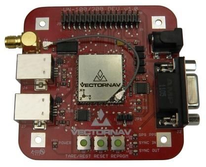
VN-200 User Manual                                                                                                             UM004

Table of Contents
1 Introduction .................................................................................. 5
  1.1    Product Description ..................................................................................... 5
  1.2    Product Features ......................................................................................... 5
  1.3    Surface-Mount Package............................................................................... 6
  1.4    Rugged Package ........................................................................................... 6
  1.5    Surface-Mount Development Kit ................................................................. 6
  1.6    VN-200 Rugged GPS/INS Development Kit .................................................. 7
  1.7    Sensor Coordinate System........................................................................... 7
2 Specifications ................................................................................ 8
  2.1    VN-200 Surface-Mount Sensor (SMD) Electrical ......................................... 8
    2.1.1     VN-200 SMD Power Supply ..................................................................................... 10
    2.1.2     VN-200 SMD Serial (UART) Interface ...................................................................... 10
    2.1.3     VN-200 SMD Serial Peripheral Interface (SPI) ........................................................ 10
    2.1.4     VN-200 SMD Reset, SyncIn/Out, and Other General I/O Pins ................................ 10
  2.2    VN-200 Rugged Electrical .......................................................................... 11
    2.2.1     VN-200 Rugged Power Supply ................................................................................ 12
    2.2.2     VN-200 Rugged Serial UART Interface .................................................................... 12
    2.2.3     VN-200 Rugged Reset, SyncIn/Out, and Other General I/O Pins ........................... 12
  2.3    VN-200 Surface-Mount Sensor (SMD) Dimensions ................................... 13
  2.4    VN-200 Rugged Dimensions ...................................................................... 14
  2.5    Absolute Maximum Ratings ....................................................................... 14
3 Basic Communication .................................................................. 15
  3.1    Serial Interface .......................................................................................... 15
  3.2    Checksum / CRC ......................................................................................... 15
    3.2.1     8-bit Checksum ....................................................................................................... 15
    3.2.2     16-bit CRC................................................................................................................ 15
  3.3    SPI Interface............................................................................................... 16
4 Communication Protocol ............................................................. 19

                                                   www.vectornav.com                                                                2/47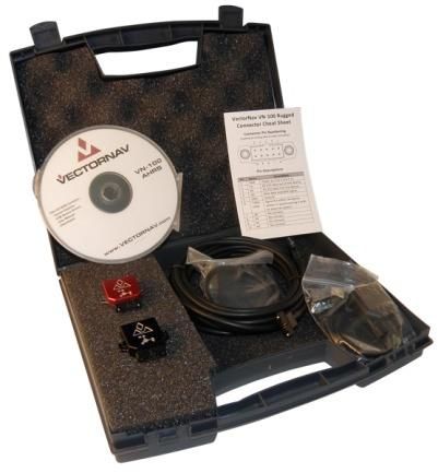
VN-200 User Manual                                                                                                               UM004

  4.1    Numeric Formats ....................................................................................... 19
  4.2    Single Precision Floating Points ................................................................. 19
  4.3    Fixed-Point Numbers ................................................................................. 19
  4.4    System Commands .................................................................................... 20
    4.4.1      Read Register Command......................................................................................... 20
    4.4.2      Write Register Command ....................................................................................... 20
    4.4.3      Write Settings Command ........................................................................................ 21
    4.4.4      Restore Factory Settings Command ....................................................................... 21
    4.4.5      Reset Command ...................................................................................................... 22
  4.5    System Error Codes ................................................................................... 23
5 System Registers ......................................................................... 24
  5.1    User Tag Register ....................................................................................... 25
  5.2    Model Number Register ............................................................................ 26
  5.3    Hardware Revision Register....................................................................... 27
  5.4    Serial Number Register .............................................................................. 28
  5.5    Firmware Version Register ........................................................................ 29
  5.6    Serial Baud Rate Register........................................................................... 30
  5.7    Async Data Output Type Register .............................................................. 31
  5.8    Async Data Output Frequency Register ..................................................... 32
  5.9    Magnetic and Gravity Reference Vectors .................................................. 33
  5.10       Reference Frame Rotation ..................................................................... 34
  5.11       Communication Protocol Control ........................................................... 35
    5.11.1     SerialCount .............................................................................................................. 35
    5.11.2     SerialStatus ............................................................................................................. 36
    5.11.3     SPICount .................................................................................................................. 36
    5.11.4     SPIStatus ................................................................................................................. 36
    5.11.5     SerialChecksum ....................................................................................................... 37
    5.11.6     SPIChecksum ........................................................................................................... 37
    5.11.7     ErrorMode ............................................................................................................... 37
  5.12       Synchronization Control ......................................................................... 38

                                                     www.vectornav.com                                                                3/47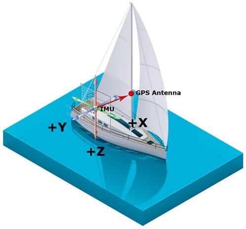
VN-200 User Manual                                                                                                            UM004

   5.12.1     SyncInMode ............................................................................................................ 38
   5.12.2     SyncInEdge .............................................................................................................. 38
   5.12.3     SyncInSkipFactor ..................................................................................................... 39
   5.12.4     SyncOutMode ......................................................................................................... 39
   5.12.5     SyncOutPolarity....................................................................................................... 39
   5.12.6     SyncOutSkipFactor .................................................................................................. 39
   5.12.7     SyncOutPulseWidth ................................................................................................ 40
 5.13       Calibrated Sensor Measurements .......................................................... 41
 5.14       GPS Configuration .................................................................................. 42
 5.15       GPS Antenna Offset ................................................................................ 43
 5.16       GPS Solution ........................................................................................... 44
 5.17       INS Solution ............................................................................................ 45
6 System Registers - Default Factory State ..................................... 46

                                                   www.vectornav.com                                                               4/47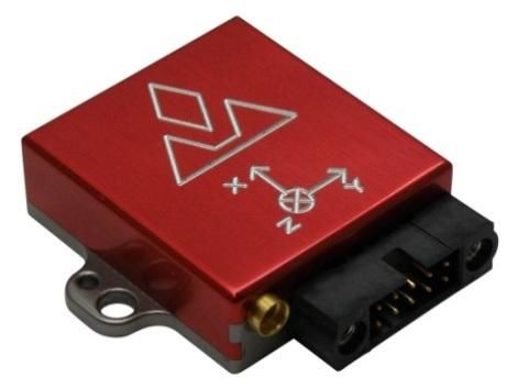
VN-200 User Manual UM004
1 Introduction
1.1 Product Description
The VN-200 is a miniature, surface-mount, high-performance Inertial Navigation System (INS).
Incorporating the latest solid-state MEMS sensor technology, the VN-200 combines 3-axis
accelerometers, 3-axis gyros, 3-axis magnetometer, a barometer, a 52-channel GPS receiver, and a 32-
bit processor into a miniature surface-mount module. Along with providing calibrated inertial sensor
measurements, the VN-200 also computes and outputs a real-time, high resolution 3D position, velocity
and drift-free orientation solution that is continuous over the complete 360 degrees of motion.
1.2 Product Features
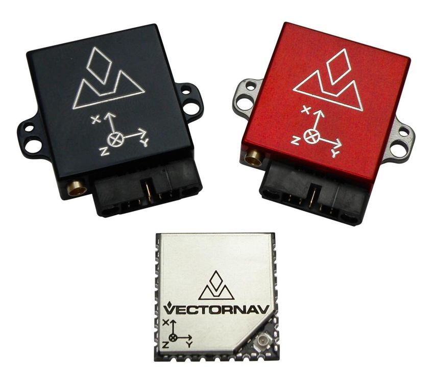
The VN-200 is available in two different configurations, as a surface-mount sensor (VN-200 SMD), or as
an enclosed sensor (VN-200 Rugged). The VN-200 Rugged provides a robust, precision anodized
aluminum clamshell enclosure, ensuring precise alignment and calibration while still retaining the
smallest possible footprint.
www.vectornav.com 5/47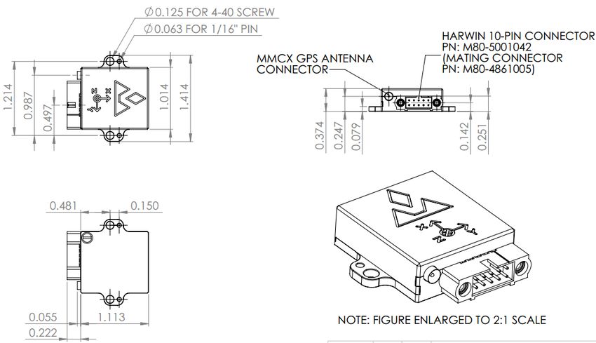
VN-200 User Manual UM004
1.3 Surface-Mount Package
For embedded applications, the VN-200 is available in a
miniature surface-mount package.
Features
Small Size: 22 x 24 x 3 mm
Single Power Supply: 3.2 to 5.5 V
Communication Interface: Serial TTL & SPI
Low Power Requirement: < 330 mW @ 3.3V
1.4 Rugged Package
The VN-200 Rugged consists of the VN-200 sensor installed in a
robust precision aluminum enclosure.
Features
Precision aluminum enclosure
Locking 10-pin connector
Mounting tabs with alignment holes
Compact Size: 34 x 36 x 9 mm
Single Power Supply: 4.5 to 5.5 V
Communication Interface: Serial RS-232 & TTL
1.5 Surface-Mount Development Kit
The VN-200 Development Kit provides the VN-200 surface-
mount sensor installed onto a small PCB, providing easy access
to all of the features and pins on the VN-200. Communication
with the VN-200 is provided by either USB or RS-232 serial
communication ports. A 20-pin header provides easy access to
each of the critical pins. The VN-200 Development Kit also
includes all of the necessary cabling, documentation, and
support software.
Features
Pre-installed VN-200 Sensor
Onboard USB->Serial converter
Onboard TTL->RS-232 converter
30-pin 0.1” header for access to VN-200 pins
Power supply jack – 5V (Can be powered from USB)
Board Size: 76 x 76 x 14 mm
www.vectornav.com 6/47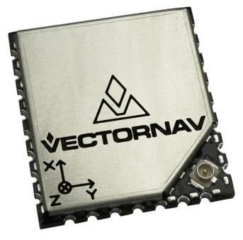
VN-200 User Manual UM004
1.6 VN-200 Rugged GPS/INS Development Kit
The VN-200 Rugged Development Kit includes the VN-200
Rugged sensor along with all of the necessary cabling required
for operation. Two cables are provided in each Development
Kit: one for RS-232 communication and a second custom cable
with a built in USB converter. The Development Kit also
includes all of the relevant documentation and support
software.
Features
(1) VN-200 Rugged Sensor
(1) 10-foot RS-232 cable
(1) 6-foot USB connector cable
1.7 Sensor Coordinate System
The VN-200 uses a right-handed coordinate system: a positive yaw angle is defined as a positive right-
handed rotation around the Z-axis; a positive pitch angle is defined as a positive right-handed rotation
around the Y-axis; and a positive roll angle is defined as a positive right-handed rotation around the X-
axis. The axes direction with respect to the VN-200 module is shown in Figure 1.
Figure 1 - VN-200 Coordinate System
www.vectornav.com 7/47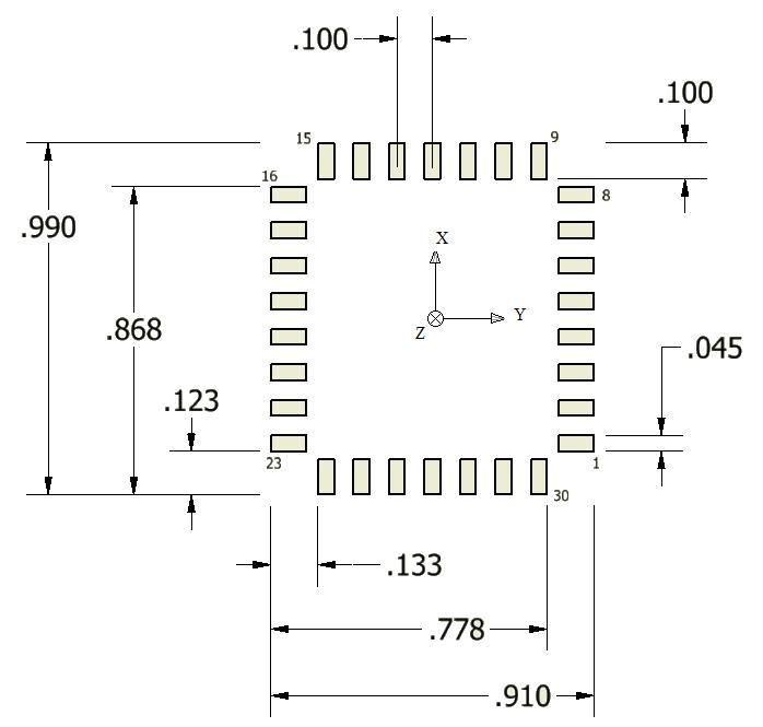
VN-200 User Manual                                                UM004

2         Specifications
    2.1    VN-200 Surface-Mount Sensor (SMD) Electrical

                     Figure 2 – Pin assignments (top down view)

                               www.vectornav.com                    8/47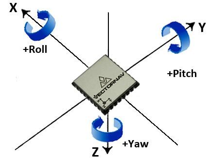
VN-200 User Manual                                                                                     UM004

                                Table 1 – VN-200 SMD Pin Assignments

   Pin #   Pin Name        Description
     1           GND       Ground.
     2           GND       Ground.
     3           GND       Ground.
     4           GND       Ground.
     5           TX2       Serial UART #2 data output. (sensor)
     6           RX2       Serial UART #2 data input. (sensor)
                           Normally used to zero (tare) the attitude.
                           To tare, pulse high for at least 1 μs. During power on or device reset, holding
     7      TARE/RESTORE   this pin high will cause the module to restore its default factory settings. As a
                           result, the pin cannot be used for tare until at least 5 ms after a
                           power on or reset. Internally held low with 10k resistor.
     8          NC         Not used.
     9       SYNC_OUT      Time synchronization output signal. See Section 5.12 for more details.
    10          VIN        3.2 - 5.5 V input.
                           Leave high for normal operation. Pull low to enter sleep mode. Internally
    11        ENABLE
                           pulled high with pull-up resistor.
    12          TX1        Serial UART #1 data output. (sensor)
    13          RX1        Serial UART #1 data input. (sensor)
    14          RESV       Reserved for future use. Leave pin floating.
                           Reserved for future use. For backwards compatibility with older hardware
                           revisions this pin can be configured in software to operate as the time
    15       SYNC_IN_2
                           synchronization input signal. For new designs it is recommended that
                           SYNC_IN (pin 22) is used instead. See Section 5.12 for more details.
    16         SPI_SCK     SPI clock.
    17        SPI_MOSI     SPI input.
    18          GND        Ground.
    19        SPI_MISO     SPI output.
                           Used to reprogram the module. Must be left floating or set to low for normal
    20        REPRGM       operation. Pull high on startup to set the VN-200 in reprogram mode.
                           Internally held low with 10k resistor.
                           Microcontroller reset line. Pull low for > 20 μs to reset MCU. Internally
    21         NRST
                           pulled high with 10k.
    22        SYNC_IN      Time synchronization input signal. See Section 5.12 for more details.
    23         SPI_CS      SPI slave select.
                           GPS time pulse. One pulse per second, synchronized at rising edge. Pulse
    24        GPS_PPS
                           width is 100 ms.
    25         VBAT        Optional GPS RTC battery backup. 1.4 V – 3.6 V input.
    26         RESV        Reserved for future use.
    27         RESV        Reserved for future use.
    28         GND         Ground.
                           Optional GPS RF input for passive antenna. The surface-mount IPX (U.FL)
    29         GPS_RF
                           connector should be used with an active GPS antenna.
    30          GND        Ground.

                                         www.vectornav.com                                                 9/47
VN-200 User Manual UM004
2.1.1 VN-200 SMD Power Supply
The minimum operating supply voltage is 3.2 V and the absolute maximum is 5.5 V.
2.1.2 VN-200 SMD Serial (UART) Interface
The serial interface on the VN-200 operates with 3 V TTL logic.
Table 2 - Serial I/O Specifications
Specification Min Typical Max
Input low level voltage -0.5 V 0.8 V
Input high level voltage 2V 5.5 V
Output low voltage 0V 0.4 V
Output high voltage 2.4 V 3.0 V
2.1.3 VN-200 SMD Serial Peripheral Interface (SPI)
Table 3 - Serial I/O Specifications
Specification Min Typical Max
Input low level voltage -0.5 V 0.8 V
Input high level voltage 2V 5.5 V
Output low voltage 0V 0.4 V
Output high voltage 2.4 V 3.0 V
Clock Frequency 8 MHz 16 MHz
Close Rise/Fall Time 8 ns
2.1.4 VN-200 SMD Reset, SyncIn/Out, and Other General I/O Pins
Table 4 - NRST Specifications
Specification Min Typical Max
Input low level voltage -0.5 V 0.8 V
Input high level voltage 2V 5.5 V
Weak pull-up equivalent resistor 30 kΩ 40 kΩ 50 kΩ
NRST pulse width 20 μs
Table 5 - SyncIn Specifications
Specification Min Typical Max
Input low level voltage -0.5 V 0.8 V
Input high level voltage 2V 5.5 V
Input Frequency 200 Hz 200 Hz 1 kHz
Pulse Width 500 μs
Table 6 - SyncOut Specifications
Specification Min Typical Max
Output low voltage 0V 0.4 V
Output high voltage 2.4 V 3.0 V
Output high to low fall time 125 ns
Output low to high rise time 125 ns
www.vectornav.com 10/47VN-200 User Manual UM004
Output Frequency 1 Hz 200 Hz
2.2 VN-200 Rugged Electrical
Table 7 – VN-200 Rugged Pin Assignments
Pin # Pin Name Description
1 VCC +5V (±0.5V)
2 TX1 RS-232 voltage levels data output from the sensor. (Serial UART #1)
3 RX1 RS-232 voltage levels data input to the sensor. (Serial UART #1)
Output signal used for synchronization purposes. Software configurable
4 SYNC_OUT
to pulse when ADC, IMU, or attitude measurements are available.
5 GND Ground
Input signal used to zero the attitude of the sensor. If high at reset, the
6 TARE/RESTORE device will restore to factory default state. Internally held low with 10k
resistor.
Input signal for synchronization purposes. Software configurable to
7 SYNC_IN either synchronize the measurements or the output with an external
device.
8 TX2_TTL Serial UART #2 data output from the device at TTL voltage level (3V).
9 RX2_TTL Serial UART #2 data into the device at TTL voltage level (3V).
10 RESV This pin should be left unconnected.
Figure 3 - VN-200 Rugged External Connector
www.vectornav.com 11/47VN-200 User Manual UM004
2.2.1 VN-200 Rugged Power Supply
The nominal power supply for the VN-200 Rugged is 5 V DC.
The VN-200 Rugged internally has overvoltage protection set at a fixed voltage of 5.8 V. Upon
an overvoltage event the protection circuitry will disable power to the VN-200 to reduce
possibility of damage to the voltage regulator onboard the VN-200.
2.2.2 VN-200 Rugged Serial UART Interface
Table 8 - Serial I/O Specifications
Specification Min Typical Max
Input low level voltage -25 V
Input high level voltage 25 V
Output low voltage -5.0 V -5.4 V
Output high voltage 5.0 V 5.5 V
Output resistance 300 Ω 10 MΩ
Data rate 1 Mbps
Pulse slew 300 ns
2.2.3 VN-200 Rugged Reset, SyncIn/Out, and Other General I/O Pins
Table 9 - NRST Specifications
Specification Min Typical Max
Input low level voltage -0.5 V 0.8 V
Input high level voltage 2V 5.5 V
Weak pull-up equivalent resistor 30 kΩ 40 kΩ 50 kΩ
NRST pulse width 20 μs
Table 10 - SyncIn Specifications
Specification Min Typical Max
Input low level voltage -0.5V 0.8V
Input high level voltage 2V 5.5V
Input Frequency 200 Hz 200 Hz 1 kHz
Pulse Width 500 μs
Table 11 - SyncOut Specifications
Specification Min Typical Max
Output low voltage 0V 0.4 V
Output high voltage 2.4 V 3.0 V
Output high to low fall time 125 ns
Output low to high rise time 125 ns
Output Frequency 1 Hz 200 Hz
www.vectornav.com 12/47VN-200 User Manual UM004
2.3 VN-200 Surface-Mount Sensor (SMD) Dimensions
Figure 4 – VN-200 PCB Footprint*
* Measurements are in inches
www.vectornav.com 13/47VN-200 User Manual UM004
2.4 VN-200 Rugged Dimensions
Figure 5 – VN-200 Rugged Dimensions
* Measurements are in inches
2.5 Absolute Maximum Ratings
Table 12 - Absolute Maximum Ratings
Specification Min Max
Input Voltage -0.3 V 5.5 V
Operating Temperature -40 C 85 C
Storage Temperature -40 C 85 C
www.vectornav.com 14/47VN-200 User Manual UM004
3 Basic Communication
The VN-200 module supports two communication interfaces: serial and SPI. On the serial interface, the
module communicates over a universal asynchronous receiver/transmitter (UART) and uses ASCII text
for its command and data format. On the SPI interface, the VN-200 module communicates as a slave
device on a Serial Peripheral Interface (SPI) data bus and uses a binary command and data format. Both
interfaces support the complete command set implemented by the module. A general overview of the
command format for each interface is given in the next two Sections and formatting specific to each
command and associated parameters is provided in the protocol and register Sections (Section 4 & 5).
3.1 Serial Interface
On the serial interface, the VN-200 uses ASCII text for its command format. All commands start with a
dollar sign, followed by a five character command, a comma, command specific parameters, an asterisk,
a checksum, and a newline character. An example command is shown below:
$VNRRG,11*73
3.2 Checksum / CRC
The serial interface provides the option for either an 8-bit checksum or a 16-bit cyclic redundancy check
(CRC). In the event neither the checksum nor the CRC is needed, they can be turned off by the user.
3.2.1 8-bit Checksum
The 8-bit checksum is an XOR of all bytes between, but not including, the dollar sign ($) and asterisk (*).
All comma delimiters are included in the checksum calculation. The resultant checksum is an 8-bit
number and is represented in the command as two hexadecimal characters. The C function snippet
below calculates the correct checksum:
unsigned char calculateChecksum(char* command, int length)
{
unsigned char xor = 0;
for(int i = 0; i < length; i++)
xor ^= (unsigned char)command[i];
return xor;
}
3.2.2 16-bit CRC
For cases where the 8-bit checksum does not provide enough error detection, a full 16-bit CRC is
available. The VN-200 uses the CRC16-CCITT algorithm. The resultant CRC is a 16-bit number and is
represented in the command as four hexadecimal characters. The C function snippet below calculates
the correct CRC:
www.vectornav.com 15/47VN-200 User Manual UM004
unsigned short calculateChecksum(char* command, int length)
{
unsigned int i;
unsigned short crc = 0;
for(i=0; i> 8) | (crc > 4;
crc ^= (crcVN-200 User Manual UM004
Figure 7 - SPI Data Diagram
A response for a given SPI command will be sent over the MISO line on the next SPI transaction. Thus
the data received by the Master on the MISO line will always be the response to the previous
transaction. For example, if Yaw, Pitch, Roll and Angular Rates are desired, then the necessary SPI
transactions would proceed as shown below:
SPI Transaction 1
Line Bytes Description
SCK 8 bytes
MOSI 01 08 00 00 00 00 00 00 (shown as hex) Read register 8 (Yaw, Pitch, Roll)
MISO 00 00 00 00 00 00 00 00 (shown as hex) No response
SPI Transaction 2
Line Bytes Description
SCK 16 bytes
01 13 00 00 00 00 00 00 00 00 00 00 00 00 00 00
MOSI (shown as hex) Read register 13 (Angular Rates)
00 01 08 00 39 8A 02 43 FD 43 97 C1 CD 9D 67 42 Yaw, Pitch, Roll = -130.54, -18.91,
MISO (shown as hex) +57.90
SPI Transaction 3
Line Bytes Description
SCK 16 bytes
00 00 00 00 00 00 00 00 00 00 00 00 00 00 00 00
MOSI (shown as hex) No command
00 01 13 00 00 F5 BF BA 00 80 12 38 B8 CC 8D 3B Rates = -0.001465, +0.000035,
MISO (shown as hex) +0.004327
During the first transaction the master sends the command to read register 8. The available registers
which can be read or written to are listed in Table 21 in Section 5. At the same time zeros are received
by the master, assuming no previous SPI command was sent to the VN-200 since reboot. On the second
transaction the master sends the command to read register 13. At the same time the response from the
previously requested register 8 is received by the master on the MISO line. It consists of four 32-bit
words. The first byte of the first word will always be zero. The second byte of the first word is the type
of command that this transaction is in response to. In this case it is a 0x01, which means that on the
previous transaction a read register command was issued. The third byte of the first word is the register
that was requested on the previous transaction. In this case it shows to be 0x08, which is the yaw, pitch,
roll register. The fourth byte of the first word is the error code for the previous transaction. Possible
www.vectornav.com 17/47VN-200 User Manual UM004
error codes are listed in Table 20 in Section 4.5. The remaining three 4-byte words are the yaw, pitch,
and roll respectively given as single-precision floating-point numbers. The floating-point numbers are
consistent with the IEEE 754 standard. On the third SPI transaction, 16 bytes are clocked on the SCK
line, during which zeros are sent by the master as no further data is required from the sensor. These 16
bytes are clocked out the SPI for the sole purpose of reading the response from the previous read
register 13 command. The response consists of four 32-bit words, starting with the zero byte, the
requested command byte, register ID, error code, and three single-precision floating-point numbers. If
only one register is required on a regular basis then this can be accomplished by sending the same
command twice to the VN-200. The response received on the second transaction will contain the most
up to date values for the desired register.
SPI Transaction 1
Line Bytes Description
SCK 16 bytes
01 08 00 00 00 00 00 00 00 00 00 00 00 00 00
MOSI 00 (shown as hex) Read register 8 (Yaw, Pitch, Roll)
00 01 08 00 39 8A 02 43 FD 43 97 C1 CD 9D 67
MISO 42 (shown as hex) Yaw, Pitch, Roll = +130.54, -18.91, +57.90
SPI Transaction 2
Line Bytes Description
SCK 16 bytes
01 08 00 00 00 00 00 00 00 00 00 00 00 00 00
MOSI 00 (shown as hex) Read Register 8 (Yaw, Pitch, Roll)
00 01 08 00 C5 9A 02 43 51 50 97 C1 32 9A 67
MISO 42 (shown as hex) Yaw, Pitch, Roll = +130.60, -18.91, +57.90
At first the device would be initialized by sending the eight bytes 01 08 00 00 00 00 00 00, requesting a
read of the yaw, pitch, roll register. The response from the second transaction would be the response to
the requested yaw, pitch, roll from the first transaction. The minimum time required between SPI
transactions is 50 µs.
www.vectornav.com 18/47VN-200 User Manual UM004
4 Communication Protocol
The following Sections describe the serial and SPI data protocol used by the VN-200.
4.1 Numeric Formats
Floating-point numbers displayed as ASCII text are presented in two formats: single/double precision
floating-point and single/double precision fixed point. In order to conserve bandwidth each variable in
the register has associated with it either a floating or fixed point representation. Any time this variable
is accessed using a read/write register command or as Async output, the variable will always use its
associated data format.
4.2 Single Precision Floating Points
Single-precision floating-point numbers are represented with seven significant digits and a two digit
exponent. Both the sign of the number and exponent are provided. The decimal point will always
follow the first significant digit. An ‘E’ will separate the significant digits from the exponential digits.
Below are some samples of correct single-precision floating-point numbers:
Single Precision Floating Point Number Examples
+9.999999E+99 -7.344409E-05
-1.234567E+01 +4.893203E+00
4.3 Fixed-Point Numbers
The fixed-point representation consists of a specified number of digits to the left and right of a fixed
decimal point. The registers that use fixed point representation and their associated formatting are
listed below. It is important to note that all numeric calculations onboard the VN-200 are performed
with 32-bit or 64-bit IEEE floating-point numbers. For the sake of simplifying the output stream, some of
these numbers are displayed in ASCII as fixed point as described below.
Table 13 – Floating Point Representation
Variable Type Fixed/Floating Variable Size Printf/Scanf Example
Yaw, Pitch, Roll Fixed 32-bit float %+08.3f +082.763
Quaternion Fixed 32-bit float %+09.6f +0.053362
Magnetic Fixed 32-bit float %+07.4f -0.3647
Acceleration Fixed 32-bit float %+07.3f -09.091
Angular Rate Fixed 32-bit float %+09.6f +00.001786
Latitude Fixed 64-bit double %+012.8f +32.95614564
www.vectornav.com 19/47VN-200 User Manual UM004
4.4 System Commands
This Section describes the list of commands available on the VN-200 module. All commands are
available in both ASCII text (UART) and binary (SPI) command formats.
The table below lists the commands available along with some quick information about the commands.
The Text ID is used to specify the command when using the text command format and the Binary ID is
used to specify the command when using the binary command format. More details about the
individual commands can be found in the referenced Section.
Table 14 – List of Available Commands
Command Name Text ID Binary ID Section
Read Register VNRRG 0x01 4.4.1
Write Register VNWRG 0x02 4.4.2
Write Settings VNWNV 0x03 4.4.3
Restore Factory Settings VNRFS 0x04 0
Reset VNRST 0x06 4.4.5
4.4.1 Read Register Command
This command allows the user to read any of the registers on the VN-200 module (see Section 5 for the
list of available registers). The only required parameter is the ID of the register to be read. The first
parameter of the response will contain the same register ID followed by a variable number of
parameters. The number of parameters and their formatting is specific to the requested register. Refer
to the appropriate register Section contained in Section 5 for details on this formatting. If an invalid
register is requested, an error code will be returned. The error code format is described in Section 4.5.
Table 15 - Example Read Register Command
Example Command Message
UART Command $VNRRG,5*46
UART Response $VNRRG,5,9600*65
SPI Command (8 bytes) 01 05 00 00 80 25 00 00 (shown as hex)
SPI Response (8 bytes) 00 01 05 00 80 25 00 00 (shown as hex)
4.4.2 Write Register Command
This command is used to write data values to a specified register on the VN-200 module (see Section 5
for the list of available registers). The ID of the register to be written to is the first parameter. This is
followed by the data values specific to that register. Refer to the appropriate register Section in Section
5 for this formatting. If an invalid register is requested, an error code will be returned. The error code
format is described in Section 4.5.
www.vectornav.com 20/47VN-200 User Manual UM004
Table 16 - Example Write Register Command
Example Command Message
UART Command $VNWRG,5,9600*60
UART Response $VNWRG,5,9600*60
SPI Command (8 bytes) 02 05 00 00 80 25 00 00 (shown as hex)
SPI Response (8 bytes) 00 02 05 00 80 25 00 00 (shown as hex)
4.4.3 Write Settings Command
This command will write the current register settings into non-volatile memory. Once the settings are
stored in non-volatile (Flash) memory, the VN-200 module can be power cycled or reset, and the register
will be reloaded from non-volatile memory. The module can always be reset to the factory settings by
issuing the Restore Factory Settings command (Section 0) or by pulling pin 7 (Tare/Restore) high during
reset.
Table 17 - Example Write Settings Command
Example Command Message
UART Command $VNWNV*57
UART Response $VNWNV*57
SPI Command (8 bytes) 03 00 00 00 00 00 00 00 (shown as hex)
SPI Response (8 bytes) 00 03 00 00 00 00 00 00 (shown as hex)
Due to limitations in the flash write speed the write settings command takes ~ 500ms to
complete. Any commands that are sent to the sensor during this time will be responded to
after the operation is complete.
4.4.4 Restore Factory Settings Command
This command will restore the VN-200 module’s factory default settings (see Section 6) and reset the
module. There are no parameters for this command. The module will respond to this command before
restoring the factory settings.
Table 18 - Example Restore Factory Settings Command
Example Command Message
UART Command $VNRFS*5F
UART Response $VNRFS*5F
SPI Command (8 bytes) 04 00 00 00 00 00 00 00 (shown as hex)
SPI Response (8 bytes) 00 04 00 00 00 00 00 00 (shown as hex)
www.vectornav.com 21/47VN-200 User Manual UM004
4.4.5 Reset Command
This command will reset the module. There are no parameters required for this command. The module
will first respond to the command and will then perform a reset. Upon a reset all registers will be
reloaded with the values saved in non-volatile memory. If no values are stored in non-volatile memory,
the device will default to factory settings. Also upon reset the VN-200 will re-initialize its Kalman filter,
thus the filter will take a few seconds to completely converge on the correct attitude and correct for
gyro bias. This command is equivalent in functionality to the hardware reset performed by pulling pin
21 (NRST) low.
Table 19 - Example Reset Command
Example Command Message
UART Command $VNRST*4D
UART Response $VNRST*4D
SPI Command (8 bytes) 06 00 00 00 00 00 00 00 (shown as hex)
SPI Response (8 bytes) 00 06 00 00 00 00 00 00 (shown as hex)
www.vectornav.com 22/47VN-200 User Manual UM004
4.5 System Error Codes
In the event of an error, the VN-200 will output $VNERR, followed by an error code. The possible error
codes are listed in the table below with a description of the error.
Table 20 – Error Codes
Error Name Code Description
If this error occurs, then the firmware on the VN-200 has experienced a
hard fault exception. To recover from this error the processor will force
Hard Fault 1
a restart, and a discontinuity will occur in the serial output. The
processor will restart within 50 ms of a hard fault error.
The processor’s serial input buffer has experienced an overflow. The
Serial Buffer Overflow 2
processor has a 256 character input buffer.
Invalid Checksum 3 The checksum for the received command was invalid.
Invalid Command 4 The user has requested an invalid command.
The user did not supply the minimum number of required parameters
Not Enough Parameters 5
for the requested command.
Too Many Parameters 6 The user supplied too many parameters for the requested command.
The user supplied a parameter for the requested command which was
Invalid Parameter 7
invalid.
Invalid Register 8 An invalid register was specified.
Unauthorized Access 9 The user does not have permission to write to this register.
A watchdog reset has occurred. In the event of a non-recoverable error
Watchdog Reset 10
the internal watchdog will reset the processor within 50 ms of the error.
The output buffer has experienced an overflow. The processor has a
Output Buffer Overflow 11
2048 character output buffer.
The baud rate is not high enough to support the requested
Insufficient Baud Rate 12
asynchronous data output at the requested data rate.
www.vectornav.com 23/47VN-200 User Manual UM004
5 System Registers
The VN-200 module contains a collection of registers used for configuring the module and accessing the
data it produces. These registers may be read or written to using the Read Register and Write Register
commands (Sections 4.4.1 and 4.4.2). When the module is rebooted or power-cycled, values written to
the registers will revert back to their previous values unless a Write Settings command has been issued
(Section 4.4.3) to save the registers to non-volatile memory.
Table 21 below provides a quick reference for all of the registers and their associated properties. The
second column lists the Access ID, which is used to identify a specific register. The third column
indicates the width of the register in bytes (relevant only in SPI mode) and the last column provides the
Section number where a more detailed explanation of the register may be found.
Each register may be read or written to using either serial or SPI communication modes. The specific
register Sections that follow describe the format used by each communication mode.
Table 21 –System Registers
Register Name Access ID Width (bytes) Section
User Tag 0 20 5.1
Model Number 1 24 5.2
Hardware Revision 2 4 5.3
Serial Number 3 12 5.4
Firmware Version 4 4 5.5
Serial Baud Rate 5 4 5.6
Asynchronous Data Output Type 6 4 5.7
Asynchronous Data Output Frequency 7 4 5.8
Magnetic and Gravity Reference Vectors 21 6x4 5.9
Reference Frame Rotation 26 9x4 5.10
Communication Protocol Control 30 7 5.11
Synchronization Control 32 20 5.12
Calibrated Sensor Measurements 54 11 x 4 5.13
GPS Configuration 55 4 5.14
GPS Antenna Offset 57 3x4 0
GPS Solution 58 68 5.16
INS Solution 63 72 5.17
www.vectornav.com 24/47VN-200 User Manual UM004
5.1 User Tag Register
User Tag
Register ID : 0 Firmware : v0.1 and up Access : Read / Write
User assigned tag register. Any values can be assigned to this register. They will be
Comment :
stored to flash upon issuing a write settings command.
Size (Bytes): 20
Example Serial Read Register
$VNRRG,00,SENSOR_A14*52
Response:
Byte Number
Offset Name Format Unit Description
0 Tag C20 - User defined tag register. Up to 20 bytes or characters.
www.vectornav.com 25/47VN-200 User Manual UM004
5.2 Model Number Register
Model Number
Register ID : 1 Firmware : v0.1 and up Access : Read Only
Comment : Model Number
Size (Bytes): 24
Example Serial Read Register
$VNRRG,01,VN-200T-DEV*77
Response:
Byte Number
Offset Name Format Unit Description
0 Product Name C24 - Product name. 24 characters.
www.vectornav.com 26/47VN-200 User Manual UM004
5.3 Hardware Revision Register
Hardware Revision Register
Register ID : 2 Firmware : v0.1 and up Access : Read Only
Comment : Hardware revision.
Size (Bytes): 4
Example Serial Read Register
$VNRRG,02,6*6B
Response:
Byte Number
Offset Name Format Unit Description
0 Revision U4 - Hardware revision.
www.vectornav.com 27/47VN-200 User Manual UM004
5.4 Serial Number Register
Serial Number
Register ID : 3 Firmware : v0.1 and up Access : Read Only
Comment : Serial Number
Size (Bytes): 12
Example Serial Read Register
$VNRRG,03,0100011981*5D
Response:
Byte Number
Offset Name Format Unit Description
0 SN[0] U4 - Serial Number (32-bit unsigned integer)
www.vectornav.com 28/47VN-200 User Manual UM004
5.5 Firmware Version Register
Firmware Version Register
Register ID : 4 Firmware : v0.1 and up Access : Read Only
Comment : Firmware version.
Size (Bytes): 4
Example Serial Read Register
$VNRRG,04,0.1.7.0*73
Response:
Byte Number
Offset Name Format Unit Description
0 Major Version U1 - Major release version of firmware.
1 Minor Version U1 - Minor release version of firmware
2 Build U1 - Build number.
3 HotFix U1 - Hot fix number.
www.vectornav.com 29/47VN-200 User Manual UM004
5.6 Serial Baud Rate Register
Serial Baud Rate
Register ID : 5 Firmware : v0.1 and up Access : Read / Write
Comment : Serial baud rate.
Size (Bytes): 4
Example Serial Read Register
$VNRRG,05,115200*5D
Response:
Byte Number
Offset Name Format Unit Description
0 Baud Rate U4 - Serial baud rate.
Optional. The serial port to change the baud rate on.
If this parameter is not provided then the baud rate will be
4 Serial Port U1 - changed for the active serial port.
1 – Serial Port 1
2 – Serial Port 2
This register specifies the baud rate of the serial data bus. The table below specifies the associated baud
rate achieved when the register is set to one of the values listed in Table 22. The response for this
command will be sent after the baud rate is changed.
Table 22 – Baud Rate Settings
Acceptable
Baud Rates
9600
19200
38400
57600
115200
128000
230400
460800
921600
The serial port parameter in this register is optional. If it is not provided, the baud rate will be
changed on the active serial port. The response to this register will include the serial port
parameter if the optional parameter is provided. If the second parameter is not provided then
the response will not include this parameter.
Upon receiving a baud rate change request, the VN-200 will send the response prior to
changing the baud rate.
www.vectornav.com 30/47VN-200 User Manual UM004
5.7 Async Data Output Type Register
Asynchronous Data Output Type
Register ID : 6 Firmware : v0.1 and up Access : Read / Write
Comment : Asynchronous data output type.
Size (Bytes): 4
Example Serial Read Register
$VNRRG,06,0*69
Response:
Byte Number
Offset Name Format Unit Description
0 ADOR U4 - Output register.
Optional. The serial port to change the asynchronous data type
on. If this parameter is not provided then the ADOR will be
4 Serial Port U1 - changed for the active serial port.
1 – Serial Port 1
2 – Serial Port 2
This register controls the type of data that will be asynchronously outputted by the module. With this
register, the user can specify which data register will be automatically outputted when it gets updated
with a new reading. Table 23 below lists which registers can be set to asynchronously output, the value
to specify which register to output, and the header of the asynchronous data packet. Asynchronous
data output can be disabled by setting this register to zero. The asynchronous data output will be sent
out automatically at a frequency specified by the Async Data Output Frequency Register (Section 5.8).
The serial port parameter in this register is optional. If it is not provided, the ADOR will be
changed on the active serial port. The response to this register will include the serial port
parameter if the optional parameter is provided. If the second parameter is not provided then
the response will not include this parameter.
Table 23 – Asynchronous Solution Output Settings
Setting Asynchronous Solution Output Type Header Formatting Section
0 Asynchronous output turned off N/A N/A
19 Calibrated Inertial Measurements VNIMU 5.13
20 GPS Measurement VNGPS 5.16
22 INS Solution VNINS 5.17
www.vectornav.com 31/47VN-200 User Manual UM004
5.8 Async Data Output Frequency Register
Asynchronous Data Output Frequency
Register ID : 7 Firmware : v0.1 and up Access : Read / Write
Comment : Asynchronous data output frequency.
Size (Bytes): 4
Example Serial Read Register
$VNRRG,07,40*5C
Response:
Byte Number
Offset Name Format Unit Description
0 ADOF U4 Hz Output frequency.
Optional. The serial port to change the asynchronous data type
frequency on. If this parameter is not provided then the ADOF will
4 Serial Port U1 - be changed for the active serial port.
1 – Serial Port 1
2 – Serial Port 2
Table 24 - ADOR Data Rates
Acceptable
Data Rates (Hz)
1
2
4
5
10
20
25
40
50
100
200
The serial port parameter in this register is optional. If it is not provided, the ADOF will be
changed on the active serial port. The response to this register will include the serial port
parameter if the optional parameter is provided. If the second parameter is not provided, the
response will not include this parameter.
www.vectornav.com 32/47VN-200 User Manual UM004
5.9 Magnetic and Gravity Reference Vectors
Magnetic and Gravity Reference Vectors
Register ID : 21 Firmware : v0.1 and up Access : Read / Write
Comment : Magnetic and gravity reference vectors.
Size (Bytes): 24
Example Serial Read
$VNRRG,21,1,0,1.8,0,0,-9.79375*53
Register Response:
Byte Number
Offset Name Format Unit Description
0 MagRefX F4 N/A X-Axis Magnetic Reference
4 MagRefY F4 N/A Y-Axis Magnetic Reference
8 MagRefZ F4 N/A Z-Axis Magnetic Reference
12 AccRefX F4 m/s^2 X-Axis Gravity Reference
16 AccRefY F4 m/s^2 Y-Axis Gravity Reference
20 AccRefZ F4 m/s^2 Z-Axis Gravity Reference
www.vectornav.com 33/47VN-200 User Manual UM004
5.10 Reference Frame Rotation
Reference Frame Rotation
Register ID : 26 Firmware : v0.1 and up Access : Read / Write
Allows the measurements of the VN-200 to be rotated into a different reference
Comment :
frame.
Size (Bytes): 36
Example Serial Read Register
$VNRRG,26,1,0,0,0,1,0,0,0,1*6A
Response:
Byte Number
Offset Name Format Unit Description
0 C[0,0] F4 -
4 C[0,1] F4 -
8 C[0,2] F4 -
12 C[1,0] F4 -
16 C[1,1] F4 -
20 C[1,2] F4 -
24 C[2,0] F4 -
28 C[2,1] F4 -
32 C[2,2] F4 -
This register contains a transformation matrix that allows for the transformation of measured
acceleration, magnetic, and angular rates from the body frame of the VN-200 to any other arbitrary
frame of reference. The use of this register allows for the sensor to be placed in any arbitrary
orientation with respect to the user’s desired body coordinate frame. This register can also be used to
correct for any orientation errors due to mounting the VN-200 on the user’s circuit board.
{ } [ ] { }
The variables { } are a measured parameter such as acceleration in the body reference frame
with respect to the VN-200. The variables { } are a measured parameter, such as acceleration in
the user’s frame of reference. The reference frame rotation register needs to be loaded with the
transformation matrix that will transform measurements from the body reference frame of the VN-200
to the desired user frame of reference. It is crucial that these two frames of reference be rigidly
attached to each other. All nine numbers are represented by single-precision floating-points.
The reference frame rotation is performed on all vector measurements prior to entering the
INS filter. As such, changing this register while the attitude filter is running may lead to
unexpected behavior in the INS output. After setting the reference frame rotation register to
its new value, send a write settings command and then reset the VN-200. This will allow the
INS filter to startup with the newly set reference frame rotation.
www.vectornav.com 34/47VN-200 User Manual UM004
5.11 Communication Protocol Control
Communication Protocol Control
Register ID : 30 Firmware : v0.1 and up Access : Read / Write
Contains parameters that control settings relating to the communication protocol
Comment :
used to communicate with the VN-200.
Size (Bytes): 7
Example Serial Read Register
$VNRRG,30,2,0,0,0,1,0,1*6E
Response:
Byte Number
Offset Name Format Unit Description
Provides the ability to append a counter to the end of the serial
0 SerialCount U1 -
asynchronous messages.
Provides the ability to append the status to the end of the serial
1 SerialStatus U1 -
asynchronous messages.
Provides the ability to append a counter to the end of the SPI
2 SPICount U1 -
packets.
Provides the ability to append the status to the end of the SPI
3 SPIStatus U1 -
packets.
4 SerialChecksum U1 - Choose the type of checksum used for serial communications.
5 SPIChecksum U1 - Choose the type of checksum used for the SPI communications.
6 ErrorMode U1 - Choose the action taken when errors are generated.
5.11.1 SerialCount
The SerialCount field provides a means of appending a time or counter to the end of all asynchronous
communication messages transmitted on the serial interface. The values for each of these counters
come directly from the Synchronization Status Register.
With the SerialCount field set to OFF, a typical serial asynchronous message would appear as the
following:
$VNYPR,+010.071,+000.278,-002.026*60
With the SerialCount field set to one of the non-zero values, the same asynchronous message would
appear instead as:
$VNYPR,+010.071,+000.278,-002.026,T1162704*2F
When the SerialCount field is enabled, the counter will always be appended to the end of the message
just prior to the checksum. The counter will be preceded by the T character to distinguish it from the
status field.
Table 25 – SerialCount Field
Mode Value Description
NONE 0 OFF
SYNCIN_COUNT 1 SyncIn Counter
SYNCIN_TIME 2 SyncIn Time
SYNCOUT_COUNT 3 SyncOut Counter
www.vectornav.com 35/47VN-200 User Manual UM004
5.11.2 SerialStatus
The SerialStatus field provides a means of tracking real-time status information pertaining to the overall
state of the sensor measurements and onboard filtering algorithm. This information is very useful in
situations where action must be taken when certain crucial events occur, such as the detection of gyro
saturation or magnetic interference. As with the SerialCount, a typical serial asynchronous message
would appear as the following:
$VNYPR,+010.071,+000.278,-002.026*60
With the SerialStatus field set to one of the non-zero values, the same asynchronous message would
appear instead as:
$VNYPR,+010.071,+000.278,-002.026,S0000*1F
When the SerialStatus field is enabled the status will always be appended to the end of the message just
prior to the checksum. If both the SerialCount and SerialStatus are enabled, the SerialStatus will be
displayed first. The counter will be preceded by the ‘S’ character to distinguish it from the counter field.
The status consists of 4 hexadecimal characters.
Table 26 – AsyncStatus
Value Description
0 OFF
1 ON
5.11.3 SPICount
The SPICount field provides a means of appending a time or counter to the end of all SPI packets. The
values for each of these counters come directly from the Synchronization Status Register.
Table 27 – SPICount Field
Mode Value Description
NONE 0 OFF
SYNCIN_COUNT 1 SyncIn Counter
SYNCIN_TIME 2 SyncIn Time
SYNCOUT_COUNT 3 SyncOut Counter
5.11.4 SPIStatus
The AsyncStatus field provides a means of tracking real-time status information pertaining to the overall
state of the sensor measurements and onboard filtering algorithm. This information is very useful in
situations where action must be taken when certain crucial events happen, such as the detection of gyro
saturation or magnetic interference.
Table 28 – SPIStatus
Value Description
0 OFF
1 ON
www.vectornav.com 36/47VN-200 User Manual UM004
5.11.5 SerialChecksum
This field controls the type of checksum used for the serial communications. Normally, the VN-200 uses
an 8-bit checksum identical to the type used for normal GPS NMEA packets. This form of checksum
however offers only a limited means of error checking. As an alternative, a full 16-bit CRC (CRC16-CCITT
with polynomial = 0x07) is also offered. The 2-byte CRC value is printed using 4 hexadecimal digits.
Table 29 – SerialChecksum
Value Description
0 OFF
1 8-Bit Checksum
2 16-Bit CRC
5.11.6 SPIChecksum
This field controls the type of checksum used for the SPI communications. The checksum is appended to
the end of the binary data packet. The 16-bit CRC is identical to the one described above for the
SerialChecksum.
Table 30 – SPIChecksum
Value Description
0 OFF
1 8-Bit Checksum
2 16-Bit CRC
5.11.7 ErrorMode
This field controls the type of action taken by the VN-200 when an error event occurs. If the send error
mode is enabled then a message similar to the one shown below will be sent on the serial bus when an
error event occurs.
$VNERR,03*72
Regardless of the state of the ErrorMode, the number of error events is always recorded and is made
available in the SysErrors field of the Communication Protocol Status Register.
Table 31 – ErrorMode
Value Description
0 Ignore Error
1 Send Error
2 Send Error and set ADOR register to OFF
www.vectornav.com 37/47VN-200 User Manual UM004
5.12 Synchronization Control
Synchronization Control
Register ID : 32 Firmware : v0.1 and up Access : Read / Write
Contains parameters which allow the timing of the VN-200 to be synchronized with
Comment :
external devices.
Size (Bytes): 20
Example Serial Read
$VNRRG,32,6,0,0,0,6,1,0,100000000,0*6E
Register Response:
Byte Number
Offset Name Format Unit Description
0 SyncInMode U1 - Input signal synchronization mode
1 SyncInEdge U1 - Input signal synchronization edge selection
2 SyncInSkipFactor U2 - Input signal trigger skip factor
4 RESERVED U4 - Reserved for future use. Defaults to 0.
8 SyncOutMode U1 - Output synchronization signal mode
9 SyncOutPolarity U1 - Output synchronization signal polarity
10 SyncOutSkipFactor U2 - Output synchronization signal skip factor
12 SyncOutPulseWidth U4 ns Output synchronization signal pulse width
16 RESERVED U4 ns Reserved for future use. Defaults to 0.
5.12.1 SyncInMode
The SyncInMode register controls the behavior of the SyncIn event. If the mode is set to COUNT, the
internal clock will be used to control the ADC timing. If SyncInMode is set to ASYNC, the ADC loop will
run on a SyncIn event. The relationship between the SyncIn event and a SyncIn trigger is defined by the
SyncInEdge and SyncInSkipFactor parameters. It is very important to note that the VN-200 must always
operate at an internal rate of 200 Hz. If the SyncIn event is used to control the ADC sampling, the SyncIn
event must be kept always at 200 Hz. If set to ASYNC, the VN-200 will output asynchronous serial
messages upon each trigger event.
Table 32 – SyncIn Mode
Mode Pin Value Description
COUNT2 SYNC_IN_2 0 Count number of trigger events on SYNC_IN_2 (pin 15).
ADC2 SYNC_IN_2 1 Start ADC sampling on trigger of SYNC_IN_2 (pin 15).
ASYNC2 SYNC_IN_2 2 Output asynchronous message on trigger of SYNC_IN_2 (pin 15).
COUNT SYNC_IN 3 Count number of trigger events on SYNC_IN (pin 22).
ADC SYNC_IN 4 Start ADC sampling on trigger of SYNC_IN (pin 22).
ASYNC SYNC_IN 5 Output asynchronous message on trigger of SYNC_IN (pin 22).
GPS_PPS GPS_PPS 6 Count number of trigger events on GPS_PPS (pin 24).
The SyncIn pin is set by default to operate on pin 22. For reverse compatibility with existing
VectorNav products it is possible to remap the SyncIn pin to operate on pin 15 instead. For
future designs it is recommended that pin 22 is used for the SyncIn feature.
www.vectornav.com 38/47VN-200 User Manual UM004
5.12.2 SyncInEdge
The SyncInEdge register controls the type of edge the signal is set to trigger on. The factory default
state is to trigger on a rising edge.
Table 33 – SyncInEdge Mode
Value Description
0 Trigger on rising edge
1 Trigger on falling edge
5.12.3 SyncInSkipFactor
The SyncInSkipFactor defines how many times trigger edges defined by SyncInEdge should occur prior to
triggering a SyncIn event. The action performed on a SyncIn event is determined by the SyncIn mode.
For example, if the SyncInSkipFactor was set to 4 and a 1 kHz signal was attached to the SyncIn pin, the
SyncIn event would only occur at 200 Hz.
5.12.4 SyncOutMode
The SyncOutMode register controls the behavior of the SyncOut pin. If this is set to ADC, the SyncOut
will start the pulse when the internal ADC loop starts. This mode is used to make a sensor the Master in
a multi-sensor network array. If this is set to IMU mode, the pulse will start when IMU measurements
become available. If this is set to INS mode, the pulse will start when INS measurements are made
available. Changes to this register take effect immediately.
Table 34 – SyncOutMode
Mode Value Description
NONE 0 None
ADC 1 Trigger at start of ADC sampling
IMU 2 Trigger when IMU measurements are available
INS 3 Trigger when INS measurements are available
GPS 6 Trigger when GPS PPS pulse is present and GPS has a position fix.
5.12.5 SyncOutPolarity
The SyncOutPolarity register controls the polarity of the output pulse on the SyncOut pin. Changes to
this register take effect immediately.
Table 35 – SyncOutPolarity
Value Description
0 Negative Pulse
1 Positive Pulse
5.12.6 SyncOutSkipFactor
The SyncOutSkipFactor defines how many times the sync out event should be skipped before actually
triggering the SyncOut pin.
www.vectornav.com 39/47VN-200 User Manual UM004
5.12.7 SyncOutPulseWidth
The SyncOutPulseWidth field controls the desired width of the SyncOut pulse.
www.vectornav.com 40/47VN-200 User Manual UM004
5.13 Calibrated Sensor Measurements
Calibrated Sensor Measurements
Register ID : 54 Firmware : v0.1 and up Access : Read Only
Comment : Calibrated measurements from all onboard sensors.
Size (Bytes): 44
Example Serial Read $VNRRG,54,+01.5656,-00.2630,+01.5138,-00.888,+00.051,-
Register Response: 09.814,+00.004525,+00.000271,+00.021949,+20.4,+00098.968*58
Byte Number
Offset Name Format Unit Description
0 MagX F4 gauss Magnetic X-axis measurement.
4 MagY F4 gauss Magnetic Y-axis measurement.
8 MagZ F4 gauss Magnetic Z-axis measurement.
12 AccelX F4 m/s2 Acceleration X-axis measurement.
16 AccelY F4 m/s2 Acceleration Y-axis measurement.
20 AccelZ F4 m/s2 Acceleration Z-axis measurement.
24 GyroX F4 rad/s X-axis angular rate.
28 GyroY F4 rad/s Y-axis angular rate.
32 GyroZ F4 rad/s Z-axis angular rate.
36 Temp F4 C Temperature.
40 Pressure F4 kPa Pressure measurement.
www.vectornav.com 41/47VN-200 User Manual UM004
5.14 GPS Configuration
GPS Configuration
Register ID : 55 Firmware : v0.1 and up Access : Read / Write
Comment :
Size (Bytes): 4
Example Serial Read
$VNRRG,55,2,0,0,0*71
Register Response:
Byte Number
Offset Name Format Unit Description
GPS mode.
0 = Use onboard GPS.
0 Mode U1 -
1 = Use external GPS with hardware PPS support.
2 = Use external GPS with software PPS support.
Selects which NMEA GPS packets are outputted on serial port #1.
1 NMEA_Serial1 U1 -
See table below for available NMEA messages.
Selects which NMEA GPS packets are outputted on serial port #2.
2 NMEA_Serial2 U1 -
See table below for available NMEA messages.
GPS NMEA message skip factor. If set to 2 then the sensor will
send out every other NMEA message. NMEA messages are
internally collected at 5Hz.
3 NMEA_Rate U1 -
0 – Off
1 – 5Hz
5 – 1Hz
GPS delay for software based PPS support. This parameter is
only used when Mode=2. Sets the number of INS filter steps the
4 GPS_Delay U1 - GPS data is delayed by. The INS filter runs at 200Hz (5ms).
0 = No delay
4 = 20ms delay
Table 36 - NMEA Messages
Name Bit Offset Description
GGA 0 Global positioning system fix data
GLL 1 Latitude and longitude
GRS 2 GNSS Range Residuals
GSA 3 GNSS DOP and Active Satellites
GST 4 GNSS Pseudo Range Error Statistics
GSV 5 GNSS Satellites in View
RMC 6 Recommended Minimum Data
VTG 7 Course over ground and Ground speed
www.vectornav.com 42/47VN-200 User Manual UM004
5.15 GPS Antenna Offset
GPS Antenna Offset
Register ID : 57 Firmware : v0.1 and up Access : Read Only
Configures the position offset of the GPS antenna from the VN-200 in the vehicle
Comment :
reference frame.
Size (Bytes): 12
Example Serial Read
$VNRRG,57,0,0,0*6D
Register Response:
Byte Number
Offset Name Format Unit Description
0 PosX F4 m Relative position of GPS antenna. (X-axis)
4 PosY F4 m Relative position of GPS antenna. (Y-axis)
8 PosZ F4 m Relative position of GPS antenna. (Z-axis)
The position of the GPS antenna relative to the sensor in the vehicle coordinate frame also referred to
as the GPS antenna lever arm. In the example scenario shown in Figure 8 below, the GPS antenna offset
is X= +2.5m, Y= +0.0m, Z= -2.0m.
Figure 8 - GPS Antenna Offset
www.vectornav.com 43/47You can also read