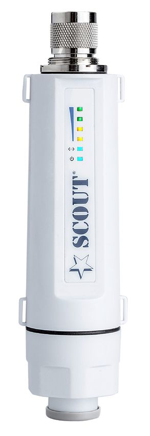
Advanced User Manual ROCKET - Ethernet - SCOUT
←
→
Page content transcription
If your browser does not render page correctly, please read the page content below
Advanced User Manual
                    ROCKET
802.11b/g/n Outdoor Access Point, Repeater, Client

                                           Ethernet

              www.scoutantenne.com                    ed. 01-2016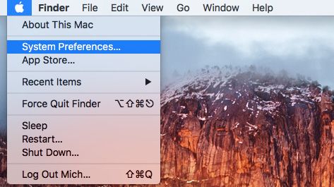
Scout                                                                                                             ROCKET Advanced User Manual

                                                                TABLE OF CONTENTS

INTRODUCTION ..................................................................................................................        3
       HARDWARE DESCRIPTION ......................................................................................                     3
       HARDWARE INSTALLATION .....................................................................................                     3
INITIAL CONFIGURATION ....................................................................................................             4
       CONNECTING TO THE LOGIN PAGE (WINDOWS) ....................................................                                     4
       CONNECTING TO THE LOGIN PAGE (MAC) ..............................................................                               6
STATUS PAGE .......................................................................................................................    7
EASY SETUP .........................................................................................................................   8
       OPERATION MODE (AP ROUTER) ............................................................................                         8
		             SETTINGS – PPPoE(ADSL) ............................................................................                     8
		             SETTINGS – STATIC (FIXED IP) ......................................................................                     9
		             SETTINGS – CABLE/DYNAMIC IP (DHCP) .....................................................                                10
		             SETTINGS – PPTP .........................................................................................               11
		             SETTINGS – L2TP .........................................................................................               12
       OPERATION MODE (AP BRIDGE) ............................................................................                         13
       OPERATION MODE (CLIENT ROUTER) .....................................................................                            13
       OPERATION MODE (CLIENT BRIDGE) ......................................................................                           15
ADVANCED SETUP ..............................................................................................................          16
       MANAGEMENT .......................................................................................................              16
       ADVANCED SETTINGS .............................................................................................                 18
       OPERATION MODE ..................................................................................................               19
FIREWALL CONFIGURATION ................................................................................................                20
       MAC/IP/PORT FILTERING ........................................................................................                  20
       VIRTUAL SERVER SETTINGS .....................................................................................                   20
       DMZ ........................................................................................................................    21
       FIREWALL ................................................................................................................       22
       CONTENT FILTERING ...............................................................................................               22
NETWORK SETTINGS ...........................................................................................................           23
       WAN ........................................................................................................................    23
		             CABLE/DYNAMIC IP (DHCP) ........................................................................                        23
		             PPPoE (ADSL) ..............................................................................................             23
		             STATIC IP (FIXED IP) .....................................................................................              24
		             PPT ..............................................................................................................      24
		             IPSec ...........................................................................................................       25
		             L2TP ............................................................................................................       25
       LAN .........................................................................................................................   26
       ADVANCED ROUTING ..............................................................................................                 26
WIRELESS SETTINGS ............................................................................................................         27
       BASIC ......................................................................................................................    27
       SECURITY .................................................................................................................      27
		             WIRED EQUIVALENT PRIVACY (WEP) ..........................................................                               28
		             WPA & WPA2 ..............................................................................................               28
		             WPA-PSK & WPA2-PSK ................................................................................                     29
		             IEEE 802.1X AND RADIUS ............................................................................                     30
		             WI-FI PROTECTED SETUP (WPS) ..................................................................                          31

                                                                                                                                            Page 2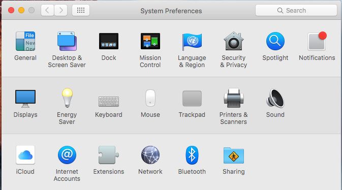
Scout                                                                                             ROCKET Advanced User Manual

INTRODUCTION

- HARDWARE DESCRIPTION

The ROCKET is a 1X1 MIMO IEEE 802.11b/g/n wireless outdoor AP/CPE which supports data rates up to 150Mbps. It is rain and
splash proof when install in upright position. The ROCKET also supports N type connector and passive PoE for simplify installation.

- HARDWARE INSTALLATION

Step 1 - Locate a suitable mounting site for your ROCKET unit. Suitable locations would be elevated area with all round clear view of
the horizon, to avoid interferences with the antenna signal. The Rocket should be mounted vertically to reduce stress on the N-Type
Connector.

Step 2 - Connect the ROCKET to the N-Type connector of the Scout KS-61 antenna (Picture 1).                ►

                                                                                                       ►

                                                                                                               ►
                                                                                                                    Picture 1
Step 3 - Connect the Ethernet cable to the port located on the bottom of the ROCKET (Picture 2).

                                                                                       Picture 2

Step 4 - Connect the other end of the Ethernet cable from the ROCKET to the Ethernet port
labeled POE on the PoE Adapter.
Then, connect the LAN port of the PoE Adapter to a PC using another Ethernet cable (please
use only wired network connections to configure the ROCKET).
Connect the power cord to the power port on the PoE Adapter. Connect the other end of
the power cord to a power outlet.

After the above steps have been completed, the final configuration will look similar to
Picture 3.                                                                                                                      Picture 3

Step 5 - Check if the LEDs on the ROCKET are displaying normally as illustrated in Picture 4.

                                                Picture 4

NOTE: If the LEDs are displaying abnormally lease check if all the cables are connected to your devices properly.

                                                                                                                                       Page 3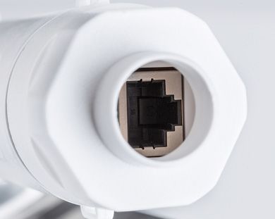
Scout                                                                                            ROCKET Advanced User Manual

INITIAL CONFIGURATION

- CONNECTING TO THE LOGIN PAGE (WINDOWS)

On your desktop look at the Task Tray in the bottom right corner, assuming you have notifications enabled you should see an icon
indication similar to that in the picture below (Picture 5).

                                                                                                   Picture 5

Position your mouse pointer over the circled icon and click the right mouse button, a dialogue box will appear, click on ‘Open Network
and Sharing Centre’. When the window in the picture below opens, click on ‘Change adapter settings’ as indicated in Picture 6.

                                                                                                   Picture 6

Click on the Local Area Connection/Ethernet icon; labeling may be different to the image in Picture 7.

                                                                                                   Picture 7

If the Local Area/Ethernet connection has a red cross on the icon you will need to right click on it and select ‘Enable’ from the top of
the list.

Next click the right mouse button and select ‘Properties’ at the bottom of the list.
When the Properties window opens, scroll down the list until you see: ‘Internet Protocol Version 4 (TCP/IPv4)’, then select it by clicking
the left mouse button, then click ‘Properties’ (Picture 8).

                                                                                                   Picture 8

Inside the Properties tab ‘Obtain an IP address automatically’ is likely to be selected, as this is the default.

Instead you will need to select ‘Use the following IP address’; this will enable the boxes and allow you to enter the numbers as shown
in Picture 9.

                                                                                                                                  Page 4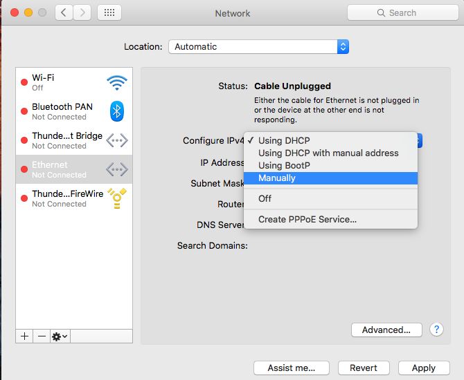
Scout                                                                                        ROCKET Advanced User Manual

                                                                                              Picture 9

Don’t close the window you have just opened as you’ll need to change this setting back later on.

Open an Internet browser and click into the Address Bar at the top of the page, then type 192.168.2.1 just like the picture below
(Picture 10), then press ENTER.

                                                                                          Picture 10

You should be greeted with the screen below (Picture 11).

                                                                                              Picture 11

Enter admin as both the user and password, then click ‘Login’.
The main status screen for the Rocket should now open, from here you can fully configure your device.

NOTE: When you have finished configuration DON’T FORGET to set your Ethernet IP address back to ‘Obtain an IP address automatically’
or you will not be able to connect to the network through your device.

                                                                                                                             Page 5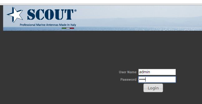
Scout                                                                               ROCKET Advanced User Manual

  - CONNECTING TO THE LOGIN PAGE (MAC)

  On your desktop go on the Apple menu and select System Preferences (Picture 12).

                                                                                     Picture 12

Then press Network button (Picture 13).

                                                                                     Picture 13

Select Ethernet on the left side menu (Picture 14).

                                                                                     Picture 14

Select Manually from the ‘Configure IPv4’ scroll menu (Picture 15).

                                                                                     Picture 15

                                                                                                            Page 6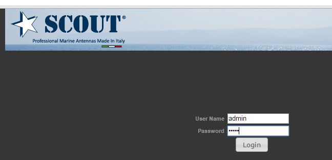
Scout                                                                                     ROCKET Advanced User Manual

Enter the numbers as shown in Picture 16, then press Apply.

                                                                                            Picture 16

Open an Internet browser and click into the Address Bar at the top of the page, then type 192.168.2.1 and press ENTER.
You should be greeted with the screen below (Picture 17).

                                                                                           Picture 17

Enter admin as both the user and password, then click ‘Login’.
The main status screen for the ROCKET should now open, from here you can fully configure your device.

NOTE: When you have finished configuration DON’T FORGET to set your Ethernet IP address back to ‘Using DHCP’ or you will not be
able to connect to the network through your device.

STATUS PAGE

After logging in to the web interface, the Status page displays. The Home page top-menu-bar shows the Status, Easy Setup, Advanced
and Language (Picture 18).

                                                                                                                         Picture 18

                                                                                                                                Page 7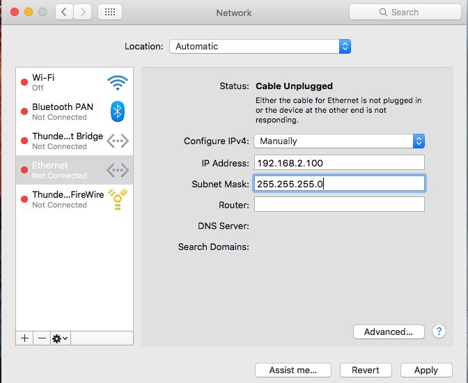
Scout                                                                                        ROCKET Advanced User Manual

EASY SETUP

The Easy Setup is designed to help you to configure the basic settings required to get the ROCKET up and running. There are only a few
basic steps you need to set up the ROCKET to get the connection.

Click on Easy Setup to bring up the wizard (Picture 19).

                                                                                                                               Picture 19

If you want to configure a router connection, please select AP Router.

If you want to configure to an access point, please select AP Bridge.

If you want to configure to WISP, please select Client Router.

If you want to configure to WiFi client, please select Client Bridge.

- OPERATION MODE (AP ROUTER)

Choose menu “Easy Setup” and select AP Router if you want to configure a router connection (Picture 20).

NOTE: The Ethernet port will convert into WAN port requiring you to configure your CPE via WLAN.

                                                                                                                               Picture 20

- - SETTINGS – PPPoE(ADSL)

1)       Select PPPoE to be assigned automatically from an Internet service provider (ISP) through a DSL modem using Point-to-Point
         Protocol over Ethernet (PPPoE) (Picture 21).

                                                                                                                               Picture 21

                                                                                                                               Page 8
Scout                                                                                           ROCKET Advanced User Manual

2)       User Name - Sets the PPPoE user name for the WAN port.
         Password - Sets a PPPoE password for the WAN port.
         Verify Password - Prompts you to re-enter your chosen password.
         Operation Mode - Enables and configures the keep alive time and configures the on-demand idle time.

                                                                                                                                   Picture 22

3)       Security Setup

         Network Name (SSID) - SSID (Service Set Identification) must be assigned to all wireless devices in your network.
         Considering your wireless network security.

         Security Mode - Select the security method and then configure the required parameters.
         (Options: Disabled, WEP-AUTO, WPA-PSK, WPA2-PSK, WPA-Auto-PSK, WPA, WPA2, WPA-Auto, 802.1X; Default: Disabled)

                                                                                                                                    Picture 23

- - SETTINGS – STATIC (FIXED IP)

1)       Select Static (Fixed IP), if your Internet service provider (ISP) to be permanent address on the Internet. A Static IP address is
         a number (in the form of a dotted quad).

                                                                                                                                    Picture 24

                                                                                                                                    Page 9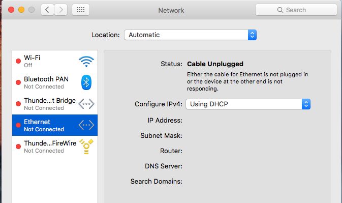
Scout                                                                                        ROCKET Advanced User Manual

2)       IP Address - Sets the static IP address.
         Subnet Mask - Sets the static IP subnet mask. (Default: 255.255.255.0)
         Default Gateway - The IP address of a router that is used when the requested destination IP address is not on the local
         subnet.
         Primary DNS Server - The IP address of the Primary Domain Name Server. A DNS maps numerical IP addresses to domain
         names and can be used to identify network hosts by familiar names instead of the IP addresses. To specify a DNS server,
         type the IP addresses in the text field provided. Otherwise, leave the text field blank.
         Secondary DNS Server - The IP address of the Secondary Domain Name Server.

                                                                                                                                  Picture 25

3)       Security Setup

         Network Name (SSID) - SSID (Service Set Identification) must be assigned to all wireless devices in your network.
         Considering your wireless network security.

         Security Mode - Select the security method and then configure the required parameters.
         (Options: Disabled, WEP-AUTO, WPA-PSK, WPA2-PSK, WPA-Auto-PSK, WPA, WPA2, WPA-Auto, 802.1X; Default: Disabled)

                                                                                                                                  Picture 26

- - SETTINGS – CABLE/DYNAMIC IP (DHCP)

1)       Select Cable/Dynamic IP (DHCP), if your Internet service provider (ISP) use a DHCP service to assign your Router an IP
         address when connecting to the Internet.

                                                                                                                                  Picture 27

                                                                                                                              Page 10
Scout ROCKET Advanced User Manual
2) The host name that you selected from the DHCP service provider.
Picture 28
3) Security Setup
Network Name (SSID) - SSID (Service Set Identification) must be assigned to all wireless devices in your network.
Considering your wireless network security.
Security Mode - Select the security method and then configure the required parameters.
(Options: Disabled, WEP-AUTO, WPA-PSK, WPA2-PSK, WPA-Auto-PSK, WPA, WPA2, WPA-Auto, 802.1X; Default: Disabled)
Picture 29
- - SETTINGS – PPTP
1) Select PPTP, if you are using PPTP service to gain connection to the Internet.
Picture 30
2) Server IP - Sets the PPTP server IP Address. (Default: pptp_server)
User Name - Sets the PPTP user name for the WAN port.
Password - Sets a PPTP password for the WAN port.
Address Mode - Sets a PPTP network mode. (Default: Dynamic IP)
Operation Mode - Enables and configures the keep alive time.
Primary DNS Server - The IP address of the Primary Domain Name Server. A DNS maps numerical IP addresses to domain
names and can be used to identify network hosts by familiar names instead of the IP addresses. To specify a DNS server,
type the IP addresses in the text field provided. Otherwise, leave the text field blank.
Page 11Scout ROCKET Advanced User Manual
Secondary DNS Server - The IP address of the Secondary Domain Name Server.
3) Security Setup
Network Name (SSID) - SSID (Service Set Identification) must be assigned to all wireless devices in your network.
Considering your wireless network security.
Security Mode - Select the security method and then configure the required parameters.
(Options: Disabled, WEP-AUTO, WPA-PSK, WPA2-PSK, WPA-Auto-PSK, WPA, WPA2, WPA-Auto, 802.1X; Default: Disabled)
Picture 31
- - SETTINGS – L2TP
1) Select L2TP, if you are using PPTP service to gain connection to the Internet.
Picture 32
2) Server IP - Sets the L2TP server IP Address. (Default: l2tp_server)
User Name - Sets the L2TP user name for the WAN port.
Password - Sets a L2TP password for the WAN port.
Address Mode - Sets a L2TP network mode. (Default: Dynamic IP)
Operation Mode - Enables and configures the keep alive time.
Primary DNS Server - The IP address of the Primary Domain Name Server. A DNS maps numerical IP addresses to domain
names and can be used to identify network hosts by familiar names instead of the IP addresses. To specify a DNS server,
type the IP addresses in the text field provided. Otherwise, leave the text field blank.
Secondary DNS Server - The IP address of the Secondary Domain Name Server.
Picture 33
Page 12Scout ROCKET Advanced User Manual
3) Security Setup
Network Name (SSID) - SSID (Service Set Identification) must be assigned to all wireless devices in your network.
Considering your wireless network security.
Security Mode - Select the security method and then configure the required parameters.
(Options: Disabled, WEP-AUTO, WPA-PSK, WPA2-PSK, WPA-Auto-PSK, WPA, WPA2, WPA-Auto, 802.1X; Default: Disabled)
Picture 34
- OPERATION MODE (AP BRIDGE)
Choose menu “Easy Setup” and select AP Bridge if you want to configure to an access point (Picture 35).
Picture 35
1) Security Setup
Network Name (SSID) - SSID (Service Set Identification) must be assigned to all wireless devices in your network.
Considering your wireless network security.
Security Mode - Select the security method and then configure the required parameters.
(Options: Disabled, Open, Shared, WEP-AUTO, WPA-PSK, WPA2-PSK, WPA-PSK_WPA2-PSK, WPA, WPA2, WPA1_WPA2,
802.1X; Default: Disabled)
Picture 36
- OPERATION MODE (CLIENT ROUTER)
The Client Router mode is also known as WISP. The ROCKET wireless side is connected to the remote AP (Base-Station) as in Client
Infrastructure mode. Between the wireless and LAN is the IP sharing router function. This is used to share Client Router connection.
The WAN is on the wireless side.
Page 13Scout ROCKET Advanced User Manual
Picture 37
1) Press Site Survey button and look for available wireless network then click on the SSID that you attempt to connect to it;
Applifer is the SSID that we are going to connect in this example. Press Next button when finished (Picture 38 - Picture 39)
Picture 38
Picture 39
2) Now, it shows the Profile Name, SSID, BSSID, and encryption type received from your target network. Press Next button
to continue (Picture 40).
Picture 40
Page 14Scout ROCKET Advanced User Manual
3) Finally, you need to tell the system about IP address received from WAN, DHCP Hostname, and DNS Server. Press Next
button to finish the wizard (Picture 41).
Picture 41
- OPERATION MODE (CLIENT BRIDGE)
In the Client Bridge mode your ROCKET will behave just the same as Wireless adapter. With Client Bridges, the WLAN and the LAN
are on the same subnet.
Picture 42
1) Press Site Survey button and look for available wireless network then click on the SSID that you attempt to connect to it;
Applifer is the SSID that we are going to connect in this example. Press Next button when finished (Picture 43 - Picture 44)
Picture 43
Picture 44
Page 15Scout ROCKET Advanced User Manual
2) Now, it shows the Profile Name, SSID, BSSID, and encryption type received from your target network. Press Next button
to continue (Picture 45).
Picture 45
ADVANCED SETUP
In the Advanced Manual Bar, it includes all the settings such as firmware upgrade, LAN, WAN and wireless settings that change the RF
behaviors. It is important to read through this section before attempting to make changes (Picture 46).
Picture 46
- MANAGEMENT
The Management section is provided for configuration of administrative needs such as language type, user name / Password, firm-
ware upgrade, export and import settings, load factory defaults and reboots system.
Page 16Scout ROCKET Advanced User Manual
Password - The new password must not exceed 32 characters in length and must not include any spaces. Enter the new password a
second time to confirm it (Picture 47).
Picture 47
Software Version - This displays the current firmware version (Picture 48).
Picture 48
To upgrade the Router’s firmware, follow these instructions below:
1. Download a more recent firmware upgrade file from our website.
2. Type the path and file name of the update file into the File field. Or click the Browse button to locate the update file.
3. Click the Upgrade button.
Note:
1. New firmware versions are posted at our website and can be downloaded for free. There is no need to upgrade the firmware unless
the new firmware has a new feature you want to use. However, when experiencing problems caused by the Router rather than the
configuration, you can try to upgrade the firmware.
2. When you upgrade the Router’s firmware, you may lose its current configurations, so before upgrading the firmware please write
down some of your customized settings to avoid losing important settings.
3. Do not turn off the Router or press the Reset button while the firmware is being upgraded, otherwise, the Router may get damaged.
4. The Router will reboot after the upgrading has been finished.
Export Settings - Click the Export Button to download current router configuration to your PC (Picture 49).
Import Settings - Click the Import Button to browse for the configuration file that is currently saved on your PC. Click Import to over-
write all current configurations with the one in the configuration file (Picture 49).
Picture 49
Page 17Scout ROCKET Advanced User Manual
Load Factory Defaults - If you have problems with the ROCKET, which might be a result from changing some settings, but you are
unsure what settings exactly, you can restore the factory defaults by click the Load Default Button (Picture 50).
Picture 50
Reboot System - If you want to reboot the TUBE-2H, click the Reboot Now Button (Picture 51)
Picture 51
- ADVANCED SETTINGS
The Advanced Settings section is provided for configuration of Time Zone, DDNS, UPnP, SNMP, and SSH (Picture 52).
Time Zone Settings - The Time Zone Settings allows you to configure, update and maintain the correct time on the ROCKET’s internal
system clock.
SNTP Server - Enter the address of an SNTP server to receive time updates.
SNTP synchronization (minutes) - Specify the interval between SNTP server updates.
Picture 52
DDNS Settings - DDNS lets you assign a fixed host and domain name to dynamic Internet IP address. It is useful when you are hosting
your own website, FTP server, or other server behind the ROCKET. Before using this feature, you need to sign up for DDNS service at
www.dyndns.org , a DDNS service provider (Picture 53).
User Name - Sets the DDNS user name for the connection.
Password - Sets a DDNS password for the connection.
HostName - The host name that you selected from the DDNS service provider.
Picture 53
Page 18Scout ROCKET Advanced User Manual
UPNP Settings - UPnP permits network devices to discover other network device(s) preference and establish functional network
services for data sharing, communication, and entrainment. Default setting is Disabled (Picture 54).
Picture 54
SMNP Settings - Managing devices on IP networks. Default setting is Disabled (Picture 55).
Picture 55
SSH Settings - Secure Shell. Enable your ROCKET unit to access secure shell (SSH) based network device. Default setting is Disabled.
(Picture 56).
Picture 56
- OPERATION MODE
The Operation Mode content four modes: AP Bridge, AP Router, Client Router and Client Bridge (Picture 57).
Picture 57
AP Bridge - The wired Ethernet and wireless are bridged together. Once the mode is selected, all WAN related functions will be disa-
bled.
AP Router - The Ethernet port will convert into WAN port requiring you to configure your CPE via WLAN.
Client Router - The ROCKET will behave just the same as the client mode for wireless function. However, router functions are added
between the wireless WAN side and the Ethernet LAN side. Therefore, the WSIP subscriber can share the WISP connection without
the extra router.
Client Bridge - The ROCKET will behave just the same as Wireless adapter. With Client Bridges, the WLAN and the LAN are on the same
subnet. Consequently, NAT is no longer used and services that are running on the original network.
Page 19Scout ROCKET Advanced User Manual
FIREWALL CONFIGURATION
- MAC/IP/PORT FILTERING
MAC/IP/Port filtering restricts connection parameters to limit the risk of intrusion and defends against a wide array of common hacker
attacks. MAC/IP/Port filtering allows the unit to permit, deny or proxy traffic through its MAC addresses, IP addresses and ports. The
ROCKET allows you define a sequential list of permit or deny filtering rules. This device tests ingress packets against the filter rules one
by one. A packet will be accepted as soon as it matches a permit rule, or dropped as soon as it matches a deny rule. If no rules match,
the packet is either accepted or dropped depending on the default policy setting (Picture 58).
Picture 58
MAC/IP/Port Filtering - Enables or disables MAC/IP/Port Filtering. (Default: Disable)
Default Policy - When MAC/IP/Port Filtering is enabled, the default policy will be enabled. If you set the default policy to “Dropped”,
all incoming packets that don’t match the rules will be dropped. If the policy is set to “Accepted,” all incoming packets that don’t match
the rules are accepted. (Default: Dropped)
MAC Address - Specifies the MAC address to block or allow traffic from.
DIP - Specifies the destination IP address to block or allow traffic from.
SIP - Specifies the source IP address to block or allow traffic from.
Protocol - Specifies the destination port type, TCP, UDP or ICMP.
Destination Port Range - Specifies the range of destination port to block traffic from the specified LAN IP address from reaching.
Source Port Range - Specifies the range of source port to block traffic from the specified LAN IP address from reaching.
Action - Specifies if traffic should be accepted or dropped. (Default: Accept)
Comment - Enter a useful comment to help identify the filtering rules.
Current Filtering rules - The Current Filter Table displays the configured IP addresses and ports that are permitted or denied access to
and from.
No. — The table entry number.
MAC Address — Displays a MAC address to filter.
Destination IP Address (DIP) — Displays the destination IP address.
Source IP Address (SIP) — Displays the source IP address.
Protocol — Displays the protocol type.
Destination Port Range (DPR) — Displays the destination port range.
Source Port Range (SPR) — Displays the source port range.
Action — Displays if the specified traffic is accepted or dropped.
Comment — Displays a useful comment to identify the filter rules.
- VIRTUAL SERVER SETTINGS
Virtual Server (sometimes referred to as Port Forwarding) is the act of forwarding traffic from one network node to another based on
received protocol port number. This technique can allow an external user to reach a port on a private IP address (inside a LAN) from
the outside through a NAT enabled router (Picture 59).
Page 20Scout ROCKET Advanced User Manual
Picture 59
Virtual Server - Selects between enabling or disabling port forwarding the virtual server. (Default: Disable)
IP Address - Specifies the IP address of a server on the local network to allow external access.
Private Port - The protocol port number on the local server.
Public Port - The protocol port number on the router’s WAN interface.
Protocol - Specifies the protocol to forward, either TCP, UDP, or TCP&UDP.
Comment - Enter a useful comment to help identify the port forwarding service on the network.
Current Virtual Servers in System - The Current Port Forwarding Table displays the entries that are allowed to forward packets through
the ROCKET’s firewall.
No. - The table entry number.
IP Address - The IP address of a server on the local network to allow external access.
Port Mapping - displays the port mapping for the server.
Protocol - Displays the protocol used for forwarding this port.
Comment - Displays a useful comment to identify the nature of the port to be forwarded.
- DMZ
DMZ is to specified host PC on the local network to access the Internet without any firewall protection. Some Internet applications,
such as interactive games or video conferencing, may not function properly behind the firewall. By specifying a Demilitarized Zone
(DMZ) host, the PC’s TCP ports are completely exposed to the Internet, allowing open two-way communication. The host PC should
be assigned a static IP address (which is mapped to its MAC address) and this must be configured as the DMZ IP address (Picture 60).
Picture 60
DMZ Settings - Sets the DMZ status. (Default: Disable)
DMZ IP Address - Specifies an IP address on the local network allowed unblocked access to the WAN.
Page 21Scout ROCKET Advanced User Manual
- FIREWALL
Firewall functions which will help to protect your network and computer. You can utilized firmware functions to protect your network
from hackers and malicious intruders (Picture 61).
Picture 61
Remote Management (via WAN) - allow or deny to manage the router from anywhere on the Internet.
Remote Management Port - The port that you will use to address the management from the Internet. For example, if you specify port
2020, then to access the ROCKET from Internet, you would use a URL of the form: http://xxx.xxx.xxx.xxx:2020/
Ping from WAN Filter - When Allow, the ROCKET does not respond to ping packets received on the WAN port.
SPI Firewall - SIP firewall help to keep track of the state of network connections (such as TCP streams, UDP communication) traveling
across it. It is programmed to distinguish legitimate packets for different types of connections. Only packets matching a known active
connection will be allowed by the firewall; others will be rejected.
Network Address Translation - NAT is the process of modifying IP address information in IP packet headers while in transit across a
traffic routing device.
- CONTENT FILTERING
The ROCKET provides a variety of options for blocking Internet access based on content, URL and host name. (Picture 62).
Picture 62
Web URL Filter Settings - By filtering inbound Uniform Resource Locators (URLs) the risk of compromising the network can be redu-
ced. URLs are commonly used to point to websites. By specifying a URL or a keyword contained in a URL traffic from that site may be
blocked.
Current URL Filters - Displays current URL filter.
Add a URL Filter - Adds a URL filter to the settings.
Page 22Scout ROCKET Advanced User Manual
Delete a URL Filter - Deletes a URL filter entry from the list.
Web Host Filter Settings - Allows Internet content access to be restricted based on web address keywords and web domains. A domain
name is the name of a particular web site. For example, for the address www.HOST.com, the domain name is HOST.com. Enter the
Keyword then click “Add.”
Current Host Filters - Displays current Host filter.
Add a Host Filter - Enters the keyword for a host filtering.
Delete a Host Filter - Deletes a Host filter entry from the list.
NETWORK SETTINGS
- WAN
In this section, there are several connection types to choose from; Static IP, DHCP, PPPoE, PPTP and L2TP. If you are unsure of your
connection method, please contact your Internet Service Provider.
- - CABLE/DYNAMIC IP (DHCP)
Picture 63
Hostname - Specifies the host name of the DHCP client.
Primary DNS Server - The IP address of the Primary Domain Name Server. A DNS maps numerical IP addresses to domain names and
can be used to identify network hosts by familiar names instead of the IP addresses. To specify a DNS server, type the IP addresses in
the text field provided. Otherwise, leave the text field blank.
Secondary DNS Server - The IP address of the Secondary Domain Name Server.
- - PPPoE (ADSL)
Picture 64
User Name - Sets the PPPoE user name for the WAN port.
Password - Sets a PPPoE password for the WAN port.
Verify Password - Prompts you to re-enter your chosen password.
Operation Mode - Enables and configures the keep alive time and configures the on-demand idle time.
Page 23Scout ROCKET Advanced User Manual
- - STATIC IP (FIXED IP)
Picture 65
IP Address - Sets the static IP address.
Subnet Mask - Sets the static IP subnet mask. (Default: 255.255.255.0)
Default Gateway - The IP address of a router that is used when the requested destination IP address is not on the local subnet.
Primary DNS Server - The IP address of the Primary Domain Name Server. A DNS maps numerical IP addresses to domain names and
can be used to identify network hosts by familiar names instead of the IP addresses. To specify a DNS server, type the IP addresses in
the text field provided. Otherwise, leave the text field blank.
Secondary DNS Server - The IP address of the Secondary Domain Name Server.
- - PPT
Picture 66
Server IP - Sets the PPTP server IP Address. (Default: pptp_server)
User Name - Sets the PPTP user name for the WAN port.
Password - Sets a PPTP password for the WAN port.
Address Mode - Sets a PPTP network mode. (Default: Dynamic IP)
Operation Mode - Enables and configures the keep alive time.
Primary DNS Server - The IP address of the Primary Domain Name Server. A DNS maps numerical IP addresses to domain names and
can be used to identify network hosts by familiar names instead of the IP addresses. To specify a DNS server, type the IP addresses in
the text field provided. Otherwise, leave the text field blank.
Secondary DNS Server - The IP address of the Secondary Domain Name Server.
Page 24Scout ROCKET Advanced User Manual
- - IPSec
Picture 67
Verify the desire settings and use scroll down for more options.
IPSec Connection Type - Use drop down menu to select from Road Warrior Tunnel, Host to Host Tunnel, Subnet to Subnet Tunnel, Host
to Host Transport, Pass trough, Drop, or Reject. Default setting is Road Warrior Tunnel
IPSec Authentication - Use drop down menu to select from SHA-1, or MD5. Default setting is SHA1.
SA Connection Life Time - Specify how often each SA should be rekeyed, measured in hour.
Local IP address / Subnet / Gateway - Local end point IP address, Subnet, and Gateway IP address.
IPSec Operation Mode - Use drop down menu to select from Add, Route Start, Manual, or Ignore. Default setting is Add.
IKE Key Retry - Specify maximum retry limits for negotiate key to Internet Key Exchange.
Peer IP address / Subnet / Gateway - Remote end point IP address, Subnet, and Gateway IP address.
- - L2TP
Picture 68
Server IP - Sets the L2TP server IP Address. (Default: l2tp_server)
User Name - Sets the L2TP user name for the WAN port.
Password - Sets a L2TP password for the WAN port.
Address Mode - Sets a L2TP network mode. (Default: Dynamic IP)
Operation Mode - Enables and configures the keep alive time.
Primary DNS Server - The IP address of the Primary Domain Name Server. A DNS maps numerical IP addresses to domain names and
can be used to identify network hosts by familiar names instead of the IP addresses. To specify a DNS server, type the IP addresses in
the text field provided. Otherwise, leave the text field blank.
Secondary DNS Server - The IP address of the Secondary Domain Name Server.
Page 25Scout ROCKET Advanced User Manual
- LAN
In this section, the LAN settings are configured based on the IP Address and Subnet Mask. The IP address is also
used to access this Web-based management interface. It is recommended to use the default settings if you do
not have an existing network (Picture 69).
Picture 69
IP Address - The IP address of ROCKET on the local area network. ( Default: 192.168.2.1 )
Subnet Mask - The subnet mask of ROCKET on the local area network
DHCP Server - The DHCP Server is to assign private IP address to the ROCKET in your local area network(LAN). The default LAN IP ad-
dress is 192.168.2.1, changing IP address will also change the DHCP server’s IP subnet.
- ADVANCED ROUTING
In this section, allow to configure routing feature in the ROCKET (Picture 70).
Picture 70
Page 26Scout ROCKET Advanced User Manual
Destination - The IP address of packets that can be routed.
Type - Defines the type of destination. (Host: Signal IP address / Net: Portion of Network)
Netmask - Displays the subnetwork associated with the destination.
Gateway - Defines the packets destination next hop.
Interface - Select interface to which a static routing subnet is to be applied.
Comment - Help identify the routing.
RIP - Enable or disable the RIP(Routing Information Protocol) for the WAN or LAN interface.
WIRELESS SETTINGS
- BASIC
Picture 71
Wireless On/Off - Enables or Disable the radio. (Default: Turn On)
Wireless Mode - There are 4 wireless mode, those are Access Point, WDS Access Point, WDS Repeater and WDS Client
Note
If WEP authentication is selected for WDS communication, you will then only have one set of encryption for the entire channel.
Network Name (SSID) - The name of the wireless network service provided by the ROCKET. Clients that want to connect to the network
must set their SSID to the same as that of the ROCKET.
Multiple SSID - One additional VAP interface supported on the device.
Frequency (Channel) - The radio channel that the ROCKET uses to communicate with wireless clients.
Network Mode - Defines the radio operating mode.
- SECURITY
Picture 72
Page 27Scout ROCKET Advanced User Manual
- - WIRED EQUIVALENT PRIVACY (WEP)
WEP provides a basic level of security, preventing unauthorized access to the network, and encrypting data transmitted between wi-
reless clients and an access point. WEP uses static shared keys (fixed-length hexadecimal or alphanumeric strings) that are manually
distributed to all clients that want to use the network.
When you select to use WEP, be sure to define at least one static WEP key for user authentication or data encryption. Also, be sure
that the WEP shared keys are the same for each client in the wireless network.
Picture 73
WEP-AUTO - Allows wireless clients to connect to the network using.
Open-WEP (uses WEP for encryption only) or Shared-WEP (uses WEP for authentication and encryption).
Encrypt Type - Selects WEP for data encryption (OPEN mode only).
Security Key Index - Selects the WEP key number to use for authentication or data encryption. If wireless clients have all four WEP
keys configured to the same values, you can change the encryption key to any of the settings without having to update the client keys.
WEP Keys - Sets WEP key values. The user must first select ASCII or hexadecimal keys. Each WEP key has an index number. Enter key
values that match the key type and length settings. Enter 5 alphanumeric characters or 10 hexadecimal digits for 64-bit keys, or enter
13 alphanumeric characters or 26 hexadecimal digits for 128-bit keys. (Default: Hex, no preset value)
Note
If WEP authentication is selected for WDS communication, you will then only have one set of encryption for the entire channel.
- - WPA & WPA2
Wi-Fi Protected Access (WPA) was introduced as an interim solution for the vulnerability of WEP pending the adoption of a more
robust wireless security standard. WPA2 includes the complete wireless security standard, but also offers backward compatibility
with WPA.
Picture 74
Page 28Scout ROCKET Advanced User Manual
WPA - Clients using WPA for authentication.
WPA2 - Clients using WPA2 for authentication.
WPA-Auto - Clients using WPA or WPA2 for authentication.
WPA Algorithms - Selects the data encryption type to use. (Default is determined by the Security Mode selected).
TKIP - Uses Temporal Key Integrity Protocol (TKIP) keys for encryption. WPA specifies TKIP as the data encryption method to replace
WEP. TKIP avoids the problems of WEP static keys by dynamically changing data encryption keys.
AES - Uses Advanced Encryption Standard (AES) keys for encryption. WPA2 uses AES Counter-Mode encryption with Cipher Block Chai-
ning Message Authentication Code (CBC-MAC) for message integrity. The AES Counter-Mode/CBCMAC Protocol (AESCCMP) provides
extremely robust data confidentiality using a 128- bit key. Use of AES-CCMP encryption is specified as a standard requirement for
WPA2. Before implementing WPA2 in the network, be sure client devices are upgraded to WPA2-compliant hardware.
Auto - Uses either TKIP or AES keys for encryption. WPA and WPA2 mixed modes allow both WPA and WPA2 clients to associate to a
common SSID. In mixed mode, the unicast encryption type (TKIP or AES) is negotiated for each client.
Key Renewal Interval - Sets the time period for automatically changing data encryption keys and redistributing them to all connected
clients.
RADIUS Server - Configures RADIUS server settings.
IP Address - Specifies the IP address of the RADIUS server.
Port - The User Datagram Protocol (UDP) port number used by the RADIUS server for authentication messages. (Range: 1024-65535;
Default: 1812)
Shared Secret - A shared text string used to encrypt messages between the access point and the RADIUS server. Be sure that the same
text string is specified on the RADIUS server. Do not use blank spaces in the string. (Maximum length: 20 characters)
- - WPA-PSK & WPA2-PSK
Wi-Fi Protected Access (WPA) was introduced as an interim solution for the vulnerability of WEP pending the adoption of a more
robust wireless security standard. WPA2 includes the complete wireless security standard, but also offers backward compatibility with
WPA. For small home or office networks, WPA and WPA2 provide a simple “personal” operating mode that uses just a pre-shared
key for network access. The WPA Pre-Shared Key (WPA-PSK) mode uses a common password phrase for user authentication that is
manually entered on the access point and all wireless clients. Data encryption keys are automatically generated by the access point
and distributed to all clients connected to the network.
Picture 75
WPA-PSK — Clients using WPA with a Pre-shared Key are accepted for authentication.
WPA2-PSK — Clients using WPA2 with a Pre-shared Key are accepted for authentication.
WPA- Auto-PSK — Clients using WPA or WPA2 with a Preshared Key are accepted for authentication. The default data encryption type
is TKIP/AES.
Page 29Scout ROCKET Advanced User Manual
WPA Algorithms - Selects the data encryption type to use. (Default is determined by the Security Mode selected.)
TKIP - Uses Temporal Key Integrity Protocol (TKIP) keys for encryption. WPA specifies TKIP as the data encryption method to
replace WEP. TKIP avoids the problems of WEP static keys by dynamically changing data encryption keys.
AES - Uses Advanced Encryption Standard (AES) keys for encryption. WPA2 uses AES Counter-Mode encryption with Cipher
Block Chaining Message Authentication Code (CBC-MAC) for message integrity. The AES Counter-Mode/CBCMAC Protocol
(AESCCMP) provides extremely robust data confidentiality using a 128- bit key. Use of AES-CCMP encryption is specified
as a standard requirement for WPA2. Before implementing WPA2 in the network, be sure client devices are upgraded to
WPA2-compliant hardware.
Auto - Uses either TKIP or AES keys for encryption. WPA and WPA2 mixed modes allow both WPA and WPA2 clients to asso
ciate to a common SSID. In mixed mode, the unicast encryption type (TKIP or AES) is negotiated for each client.
Pass Phrase - The WPA Preshared Key can be input as an ASCII string (an easy-to-remember form of letters and numbers that can in-
clude spaces) or Hexadecimal format. (Range: 8~63 ASCII characters, or exactly 64 Hexadecimal digits)
Key Renewal Interval - Sets the time period for automatically changing data encryption keys and redistributing them to all connected
clients.
- - IEEE 802.1X AND RADIUS
IEEE 802.1X is a standard framework for network access control that uses a central RADIUS server for user authentication. This
control feature prevents unauthorized access to the network by requiring an 802.1X client application to submit user credentials
for authentication. The 802.1X standard uses the Extensible Authentication Protocol (EAP) to pass user credentials (either digital
certificates, user names and passwords, or other) from the client to the RADIUS server. Client authentication is then verified on the
RADIUS server before the client can access the network. Remote Authentication Dial-in User Service (RADIUS) is an authentication
protocol that uses software running on a central server to control access to RADIUS-aware devices on the network. An authentication
server contains a database of user credentials for each user that requires network access.
The WPA and WPA2 enterprise security modes use 802.1X as the method of user authentication. IEEE 802.1X can also be enabled on
its own as a security mode for user authentication. When 802.1X is used, a RADIUS server must be configured and be available on the
connected wired network.
Picture 76
RADIUS Server - Configures RADIUS server settings.
IP Address - Specifies the IP address of the RADIUS server.
Port - The User Datagram Protocol (UDP) port number used by the RADIUS server for authentication messages. (Range: 1024-65535;
Default: 1812)
Shared Secret - A shared text string used to encrypt messages between the access point and the RADIUS server. Be sure that the same
text string is specified on the RADIUS server. Do not use blank spaces in the string. (Maximum length: 20 characters)
Page 30Scout ROCKET Advanced User Manual
- - WI-FI PROTECTED SETUP (WPS)
Wi-Fi Protected Setup (WPS) is designed to ease installation and activation of security features in wireless networks. WPS has two basic
modes of operation, Push-button Configuration (PBC) and Personal Identification Number (PIN). The WPS PIN setup is optional to the
PBC setup and provides more security. The WPS button on the Wireless Router can be pressed at any time to allow a single device
to easily join the network. The WPS Settings page includes configuration options for setting WPS device PIN codes and activating the
virtual WPS button (Picture 77).
Picture 77
WPS SSID - The service set identifier for the unit.
AP PIN - Displays the PIN Code for the Wireless Router.
Device Name - WPS name for connecting to the device.
Encryption Settings - Selects between methods of broadcasting the WPS beacon to network clients wanting to join the network:
WPA Algorithms - Select the data encryption type to use. (Default is determined by the Security Mode selected.)
TKIP - Uses Temporal Key Integrity Protocol (TKIP) keys for encryption. WPA specifies TKIP as the data encryption method to replace
WEP. TKIP avoids the problems of WEP static keys by dynamically changing data encryption keys.
AES - Uses Advanced Encryption Standard (AES) keys for encryption. WPA2 uses AES Counter-Mode encryption with Cipher Block Chai-
ning Message Authentication Code (CBC-MAC) for message integrity. The AES Counter-Mode/CBCMAC Protocol (AESCCMP) provides
extremely robust data confidentiality using a 128- bit key. Use of AES-CCMP encryption is specified as a standard requirement for
WPA2. Before implementing WPA2 in the network, be sure client devices are upgraded to WPA2-compliant hardware.
Auto - Uses either TKIP or AES keys for encryption. WPA and WPA2 mixed modes allow both WPA and WPA2 clients to associate to a
common SSID. In mixed mode, the unicast encryption type (TKIP or AES) is negotiated for each client.
Key Renewal Interval - Sets the time period for automatically changing data encryption keys and redistributing them to all connected
clients.
Pass Phrase - The WPA Preshared Key can be input as an ASCII string (an easy-to-remember form of letters and numbers that can in-
clude spaces) or Hexadecimal format. (Range: 8~63 ASCII characters, or exactly 64 Hexadecimal digits)
Page 31You can also read