SpeedFlow 2.0-Pipe Speed measurement of solids - EN
←
→
Page content transcription
If your browser does not render page correctly, please read the page content below
EN

                         SpeedFlow 2.0-Pipe
                         Speed measurement of solids
Operating Instructions

                               SWR engineering Messtechnik GmbH PART OF THE ENVEA GROUP
CONTENTS                                                                                                                                                       Page
1.     System overview .  .  .  .  .  .  .  .  .  .  .  .  .  .  .  .  .  .  .  .  .  .  .  .  .  .  .  .  .  .  .  .  .  .  .  .  .  .  .  .  .  .  .  .  .  3
2.     Function  .  .  .  .  .  .  .  .  .  .  .  .  .  .  .  .  .  .  .  .  .  .  .  .  .  .  .  .  .  .  .  .  .  .  .  .  .  .  .  .  .  .  .  .  .  .  .  .  .  4
3.     Safety  .  .  .  .  .  .  .  .  .  .  .  .  .  .  .  .  .  .  .  .  .  .  .  .  .  .  .  .  .  .  .  .  .  .  .  .  .  .  .  .  .  .  .  .  .  .  .  .  .  .  . 5
       3.1 Normal use  .  .  .  .  .  .  .  .  .  .  .  .  .  .  .  .  .  .  .  .  .  .  .  .  .  .  .  .  .  .  .  .  .  .  .  .  .  .  .  .  .  .  .  .  .  5
       3.2 Identification of hazards  .  .  .  .  .  .  .  .  .  .  .  .  .  .  .  .  .  .  .  .  .  .  .  .  .  .  .  .  .  .  .  .  .  .  .  .  .  .  5
       3.3 Operational safety  .  .  .  .  .  .  .  .  .  .  .  .  .  .  .  .  .  .  .  .  .  .  .  .  .  .  .  .  .  .  .  .  .  .  .  .  .  .  .  .  .  . 5
       3.4 Technical statement  .  .  .  .  .  .  .  .  .  .  .  .  .  .  .  .  .  .  .  .  .  .  .  .  .  .  .  .  .  .  .  .  .  .  .  .  .  .  .  .  . 5
4.     Mounting and installation  .  .  .  .  .  .  .  .  .  .  .  .  .  .  .  .  .  .  .  .  .  .  .  .  .  .  .  .  .  .  .  .  .  .  .  .  .  .  .  . 6
       4.1 Typical components of the measurement point .  .  .  .  .  .  .  .  .  .  .  .  .  .  .  .  .  .  .  .  .  .  .  .  .  .  6
       4.2 Required tools  .  .  .  .  .  .  .  .  .  .  .  .  .  .  .  .  .  .  .  .  .  .  .  .  .  .  .  .  .  .  .  .  .  .  .  .  .  .  .  .  .  .  .  . 6
       4.3 Mounting of the sensor  .  .  .  .  .  .  .  .  .  .  .  .  .  .  .  .  .  .  .  .  .  .  .  .  .  .  .  .  .  .  .  .  .  .  .  .  .  .  6
       4.4 Mounting of the transmitter  .  .  .  .  .  .  .  .  .  .  .  .  .  .  .  .  .  .  .  .  .  .  .  .  .  .  .  .  .  .  .  .  .  .  .  .  7
5.     Electrical connection  .  .  .  .  .  .  .  .  .  .  .  .  .  .  .  .  .  .  .  .  .  .  .  .  .  .  .  .  .  .  .  .  .  .  .  .  .  .  .  .  .  .  9
       5.1 DIN Rail terminal layout  .  .  .  .  .  .  .  .  .  .  .  .  .  .  .  .  .  .  .  .  .  .  .  .  .  .  .  .  .  .  .  .  .  .  .  .  .  .  9
       5.2 Electrical connection of the sensor  .  .  .  .  .  .  .  .  .  .  .  .  .  .  .  .  .  .  .  .  .  .  .  .  .  .  .  .  .  .  .  .  10
       5.3 Field housing terminal layout  .  .  .  .  .  .  .  .  .  .  .  .  .  .  .  .  .  .  .  .  .  .  .  .  .  .  .  .  .  .  .  .  .  .  . 11
       5.4 C1-Box terminal layout .  .  .  .  .  .  .  .  .  .  .  .  .  .  .  .  .  .  .  .  .  .  .  .  .  .  .  .  .  .  .  .  .  .  .  .  .  .  . 12
6.     Operator interface  .  .  .  .  .  .  .  .  .  .  .  .  .  .  .  .  .  .  .  .  .  .  .  .  .  .  .  .  .  .  .  .  .  .  .  .  .  .  .  .  .  .  . 13
       6.1 Differences between DIN Rail and field housing transmitter  .  .  .  .  .  .  .  .  .  .  .  .  .  .  .  .  .  . 13
       6.2 Display  .  .  .  .  .  .  .  .  .  .  .  .  .  .  .  .  .  .  .  .  .  .  .  .  .  .  .  .  .  .  .  .  .  .  .  .  .  .  .  .  .  .  .  .  .  .  .  14
       6.3 PC interface  .  .  .  .  .  .  .  .  .  .  .  .  .  .  .  .  .  .  .  .  .  .  .  .  .  .  .  .  .  .  .  .  .  .  .  .  .  .  .  .  .  .  .  . 16
       6.4 Menu structure .  .  .  .  .  .  .  .  .  .  .  .  .  .  .  .  .  .  .  .  .  .  .  .  .  .  .  .  .  .  .  .  .  .  .  .  .  .  .  .  .  .  . 18
7.     Start-up procedure  .  .  .  .  .  .  .  .  .  .  .  .  .  .  .  .  .  .  .  .  .  .  .  .  .  .  .  .  .  .  .  .  .  .  .  .  .  .  .  .  .  .  . 28
       7.1 Basic start-up procedure  .  .  .  .  .  .  .  .  .  .  .  .  .  .  .  .  .  .  .  .  .  .  .  .  .  .  .  .  .  .  .  .  .  .  .  .  . 28
       7.2 Adjusting the measurement values  .  .  .  .  .  .  .  .  .  .  .  .  .  .  .  .  .  .  .  .  .  .  .  .  .  .  .  .  .  .  .  . 28
8.     Error signalling  .  .  .  .  .  .  .  .  .  .  .  .  .  .  .  .  .  .  .  .  .  .  .  .  .  .  .  .  .  .  .  .  .  .  .  .  .  .  .  .  .  .  .  .  . 29
9.     Maintenance . . . . . . . . . . . . . . . . . . . . . . . . . . . . . . . . . . . . . . . . . . . . . . 30
10. Warranty .  .  .  .  .  .  .  .  .  .  .  .  .  .  .  .  .  .  .  .  .  .  .  .  .  .  .  .  .  .  .  .  .  .  .  .  .  .  .  .  .  .  .  .  .  .  .  .  . 30
11. Fault clearance  .  .  .  .  .  .  .  .  .  .  .  .  .  .  .  .  .  .  .  .  .  .  .  .  .  .  .  .  .  .  .  .  .  .  .  .  .  .  .  .  .  .  .  .  . 30
       11.1 Error codes  .  .  .  .  .  .  .  .  .  .  .  .  .  .  .  .  .  .  .  .  .  .  .  .  .  .  .  .  .  .  .  .  .  .  .  .  .  .  .  .  .  .  .  . 31
12. Technical data .  .  .  .  .  .  .  .  .  .  .  .  .  .  .  .  .  .  .  .  .  .  .  .  .  .  .  .  .  .  .  .  .  .  .  .  .  .  .  .  .  .  .  .  .  .  32

                                                                                                                                                                      2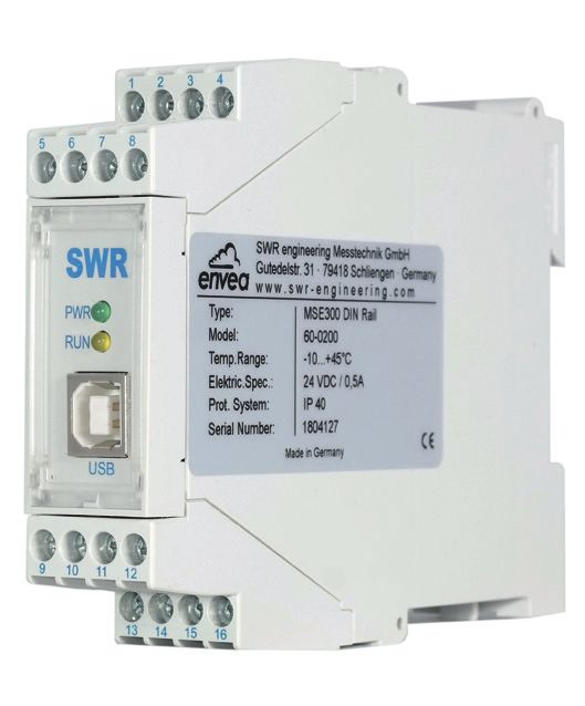
1. System overview
      A complete measuring point consists of the following components:

      ••   Transmitter in the DIN Rail housing or field housing
      ••   Sensor
      ••   Installation instructions
      ••   C1-Box (optional)

                                                        C1-Box

              Sensor                           C1-Box                            Transmitter
                                                                               1 (+ 24 V)
                                                                               2 (GND)
                                                                               3 (A)
                                                                               4 (B)
                                                                               S (Earth)

                                  2m                              max. 300 m

Fig. 1: Overview with C1-Box and field housing transmitter

                                                         C1-Box

               Sensor                           C1-Box                           Transmitter
                                                                               16 (+ 24 V)
                                                                               15 (GND)
                                                                               14 (A)
                                                                               13 (B)

                                  2m                              max. 300 m

Fig. 2: Overview with C1-Box and DIN Rail transmitter

                                                                                               3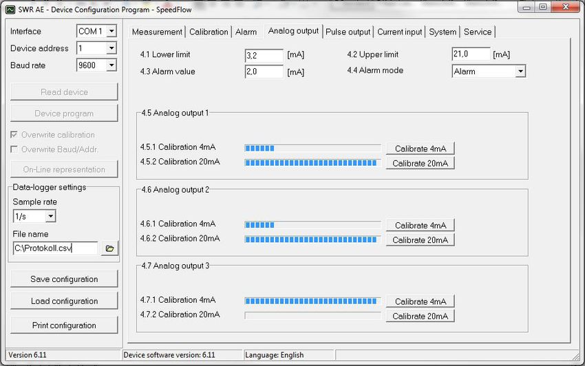
2. Function
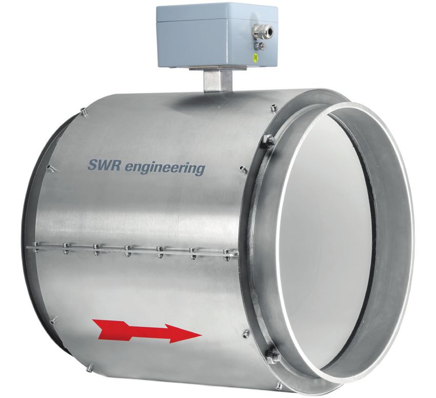
•• The SpeedFlow 2.0-Pipe is a measuring system which has been specially developed for measuring the
speed of solids being transported.
•• The sensor works according to the electrodynamic principle and can be used for the diameters:
DN 80, DN 100, DN 150, DN 200, DN 350
•• The electrodes used receive an electrical pulse from the solid particles as they pass. The received
signals are evaluated using an auto-correlation process which thus calculates the speed.
•• The SpeedFlow 2.0-Pipe is used to measure solids in unpressurised air supply lines.
•• The SpeedFlow 2.0-Pipe works even more efficiently and reliably due to the use of new processor
technologies.
Fig. 3: SpeedFlow 2.0-Pipe sensor in the pipeline
4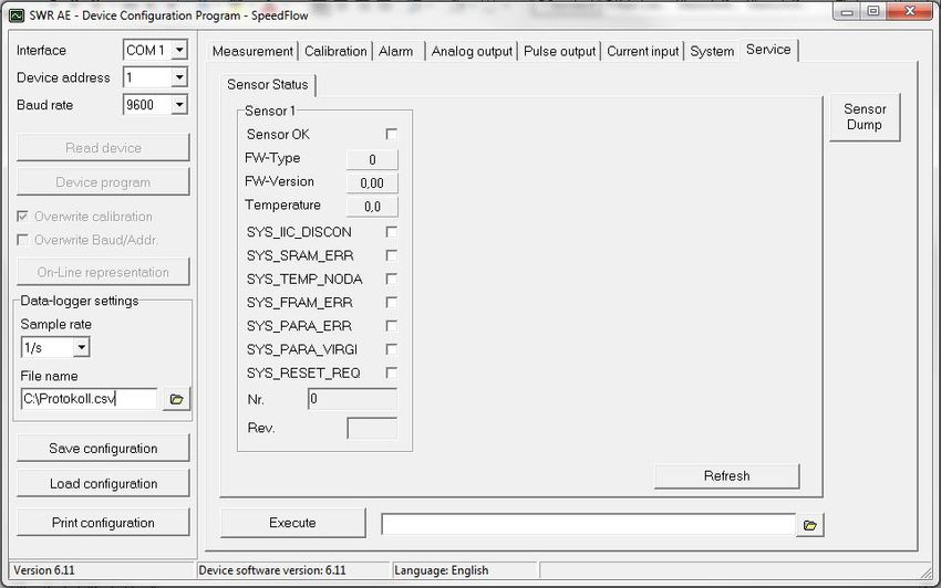
3. Safety
The SpeedFlow 2.0-Pipe measuring system has a state of the art, reliable design. It was tested and found to be in
a perfectly safe condition when leaving the factory. Nevertheless, the system components may present dangers to
personnel and items if they are not operated correctly.
Therefore, the operating manual must be read in full and the safety instructions followed to the letter.
If the device is not used correctly for its intended purpose the manufacturer's liability and warranty will be void.

3.1 Normal use
      ••    The measuring system may only be installed in metallic pipes to measure the speed of the medium
            passing through them.
            It is not suitable for any other use or measuring system modifications.
      ••    Only genuine spare parts and accessories from ENVEA - SWR engineering may be used.

3.2 Identification of hazards
      ••    Possible dangers when using the measuring system are highlighted in the operating manual with the
            following symbols:

      Warning!
      •• This symbol is used in the operating manual to denote actions which, if not performed correctly may
         result in death or injury.

      Attention!
      •• This symbol is used in the operating manual to denote actions which may result in danger to property.

3.3   Operational safety
      ••    The measuring system may only be installed by trained, authorised personnel.
      ••    During all maintenance, cleaning and inspection work on the pipelines or components of ENVEA -
            SWR engineering, make sure that the system is in an unpressurised state.
      ••    Switch off the power supply before performing any maintenance work, cleaning work or inspections on
            the pipelines or the SpeedFlow 2.0-Pipe components.
      ••    The sensor must be taken out of the pipeline before any welding work is performed.
      ••    The components and electrical connections must be inspected for damage at regular intervals. If any
            signs of damage are found, they must be rectified before the devices are used again.

3.4        Technical statement
      ••    The manufacturer reserves the right to adjust technical data concerning technical developments without
            notice. ENVEA - SWR engineering will be delighted to provide information about the current version of
            the operating manual, and any amendments made.

                                                                                                                       5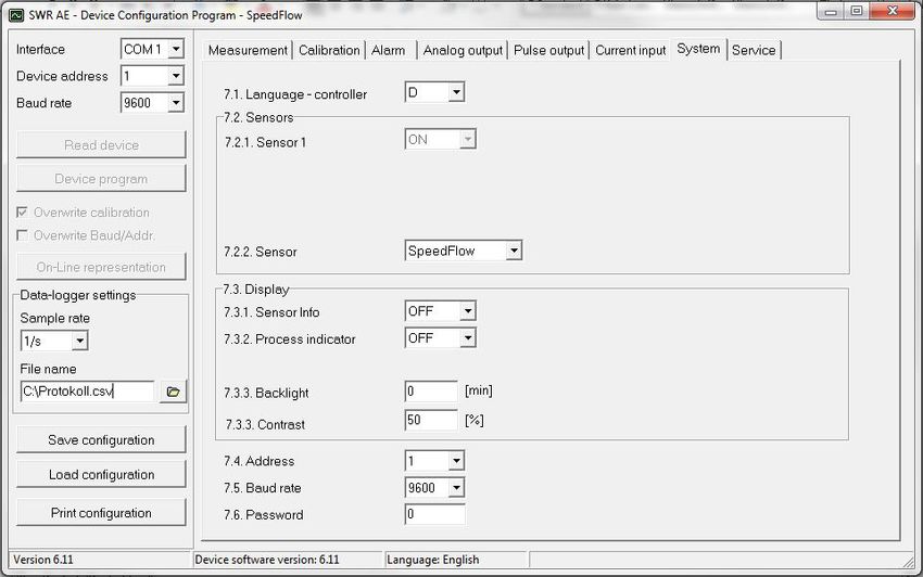
4.     Mounting and installation
4.1 Typical components of the measurement point:
      ••   Transmitter in the DIN Rail housing or field housing
      ••   Sensor
      ••   Installation instructions
      ••   Optional: C1-Box

4.2 Required tools
      ••   Tested tools for the electrical connection
      ••   Appropriate tools for integrating the sensor

4.3 Mounting of the sensor
      Proceed as follows to install the sensor:

      ••   Decide on the installation position in your line routeing. For horizontal or inclined pipelines, the terminal
           box should always be aligned facing upwards.

      ••   The sensor should be installed as strain-free as possible.

      ••   The SpeedFlow 2.0-Pipe must be installed in the direction of the flow.
      ••   The distances apply to vertical and horizontal installations.
      ••   Ensure that the measurement point is at an adequate distance from valves, manifolds, blowers and
           bucket wheel feeders and other measurement ports such as those used for pressure and temperature
           sensors, etc. (See fig. 4)

                                                    3 x DN            2 x DN
                                                  DN

                                            8 x DN (min. 1 m)          4 x DN

                                           10 x DN (min. 1 m)          5 x DN

                                            8 x DN (min. 1 m)          4 x DN

Fig. 4: Minimum distances of the measurement point from pipe geometries and fittings

      ••   The standard connection to the existing line is made via a JACOBS pipe connection. Various adapters
           can be procured from ENVEA - SWR engineering.

                                                                                                                       6
4.4 Mounting of the transmitter
        The transmitter can be installed at a maximum distance of 300 m from the sensor.
        A cable of the type "Ölflex Classic 110 CY" is recommended. The cable should be four-core, twisted in pairs
        and shielded. A minimum cross section of 0.75 mm² should be maintained. For distances longer than 150 m,
        the cross-section should be adjusted.

                        23                                                         118

              1    2     3   4

              5    6     7   8

                   PWR
                   RUN
                                              35
   90

                   USB

              9    10   11   12

              13   14   15   16

Fig. 5: Dimensions of the transmitter in the DIN Rail housing

Fig. 6: Dimensions of the transmitter in the field housing (front view)

                                                                                                                  7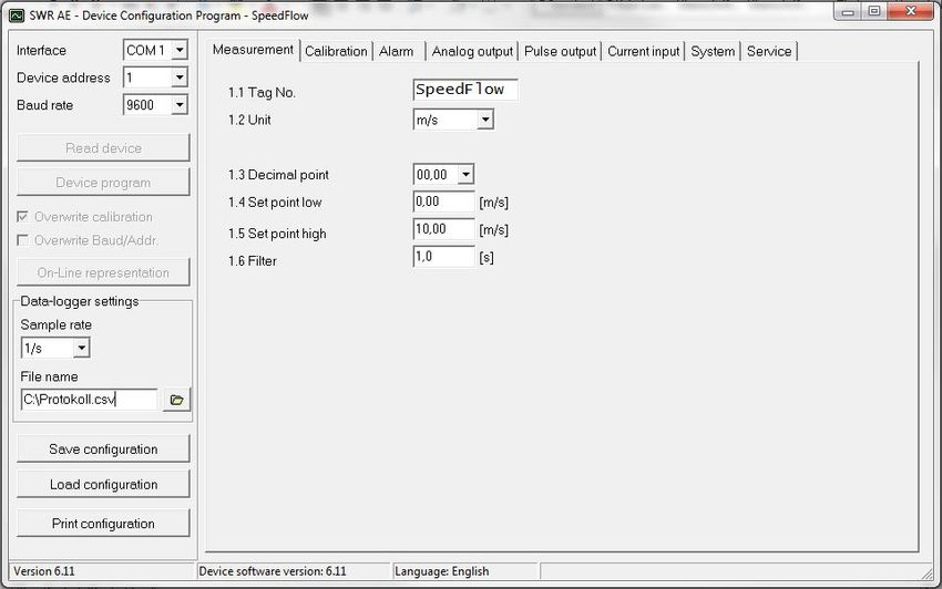
Fig. 7: Dimensions of the transmitter in the field housing (side view)

                              113 mm

                                                                      m                            125 mm
                                                               4,8 m
                                                                     80 mm
                                                             52 mm

                                                                                                            57 mm
           mm
     4,8
                                                                                                   50 mm

                     max.              max.
                    13 mm             13 mm

Fig. 8: C1-Box dimensions

                                              Threaded bolt M6x15            Threaded bolt M6x15

Fig. 9: Dimensions of the SpeedFlow 2.0-Pipe sensor

                                                                                                                    8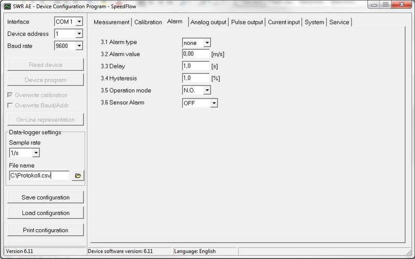
5.    Electrical connection
5.1   DIN Rail terminal layout

 1 Current output         2 Current output                  3 Input                    4 Input
      - 4 ... 20 mA            + 4 ... 20 mA                     Power supply             Power supply
                                                                 0 V DC                   + 24 V DC

 5 Not used               6 Alarm relay                     7 Alarm relay              8 Alarm relay
                               NC (break contact)                C                        NO (make contact)

                                                 1    2     3     4

                                                 5    6     7     8

                                                     PWR
                                                     RUN

                                                       USB

                                                 9    10   11    12

                                                13    14 15      16

                         Fig. 10: Electrical connection for the DIN Rail transmitter

  9 Digital              10 Digital                        11 RS 485-                  12 RS 485-
      pulse output (-)         pulse output (+)                  Interface                Interface
                                                                 Data B                   Data A

 13 Sensor connection    14 Sensor connection              15 Sensor connection        16 Sensor connection
      Cable 4                  Cable 3                           Cable 2                  Cable 1
      RS 485                   RS 485                            Power                    Power
      Data B                   Data A                            supply 0 V               supply + 24 V

                                                                                                              9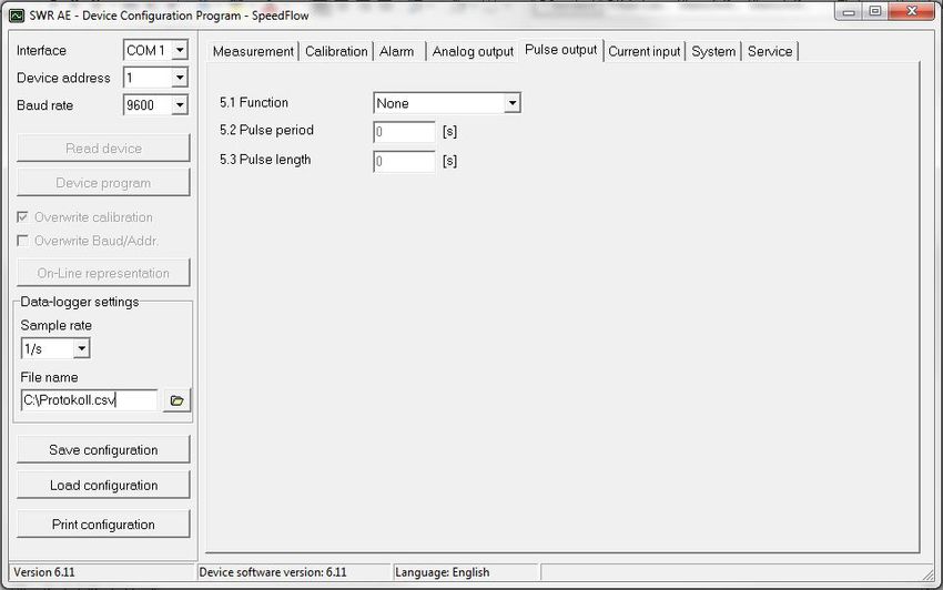
5.2   Electrical connection of the sensor
      The sensor can be delivered with a 4-pole plug connector or with an M12 plug.

5.2.1 Electrical connection of the sensor plug contact
      Pin 1:    +24 V DC

      Pin 2:

      Pin 3:
                GND

                ModBus A                                               1 2 3 4
      Pin 4:    ModBus B

                                                            Fig. 11: Electrical connection of the plug connector

5.2.2 Electrical connection of the sensor M12 plug
      Pin 1:    +24 V DC
                                                                             Pin assignment
      Pin 2:    GND                                                          Connection plug
      Pin 3:    ModBus A

      Pin 4:    ModBus B
                                                                                                         2

                                                                   3                                         1

                                                                        4

                                                            Fig. 12: Electrical connection of M12 plug

                                                                                                                   10
5.3 Field housing terminal layout
L N PE + - + - + - + - NO C NC + - A B GND + - + - + - A B Shield
I-in 1 I-out 1 I-out 2 I-out 3 Alarm Relay D-out RS 485 D-in 1 D-in 2 Sensor
Fig. 13: Electrical connection for transmitter in the field housing
Transmitter
Terminal No. Connection
Power supply connection
L / +24 V Input power supply 230 V / 50 Hz, 110 V / 60 Hz (optional 24 V DC)
N/0V Input power supply 230 V / 50 Hz, 110 V / 60 Hz (optional 24 V DC)
PE Protective Earth
Connections
+ Current input +
I-in1
- Current input –
+ Current output +
I-out1
- Current output –
Na Not used
Na Not used
Na Not used
Na Not used
NO Floating change-over contact NO (make contact)
Min. /
C Floating change-over contact C (common contact)
Max. relay
NC Floating change-over contact NC (break contact)
+ Digital pulse output +
D-out
- Digital pulse output –
A RS 485 interface data A
RS 485 B RS 485 interface data B
GND RS 485 interface ground
Na Not used
D-in1
Na Not used
Na Not used
D-in2
Na Not used
+ Power supply + 24 V Cable no. 1
GND Power supply 0 V Cable no. 2
Sensor A RS 485 data A Cable no. 3
B RS 485 data B Cable no. 4
Shield Shield
115.4 C1-Box terminal layout
Sensor 1 Transmitter
Cable gland
M 20 x 1.5
Fig. 14: Electrical connection of C1-Box
126. Operator interface
The transmitter is a multi-sensor transmitter. It is therefore strongly recommended to check whether the correct
sensor is selected in the System menu item before commissioning.
The operator interface differs depending on the selected transmitter:
•• DIN Rail housing without display, operation via PC software
•• Field housing with display, alternative operation via PC software
First of all, the different system versions are described below. Following that, the basic operation of the SpeedFlow 2.0-
Pipe system as a one sensor system is then described without going back over the different versions.
6.1 Differences between DIN Rail and field housing transmitter
The transmitter in the DIN Rail housing is only a part of the functions available in the field housing.
The following overview clarifies the differences between the two versions.
Function Field housing DIN Rail
Menu system
•• via PC software yes yes
•• via display yes no
Measurement value display current output yes yes
Pulse output to control solenoid valves yes yes
or output the measured value
Alarm system relay output yes yes
Autocorrect analogue input yes no
Error output
•• on current output yes yes
•• at relay yes yes
•• via PC software yes yes
•• via display yes no
•• At status LED no yes
The transmitter in the DIN Rail can only be configured via a USB connection and PC programme. On the
transmitter in the field housing, all functions can be configured by menu via the touch-sensitive display.
The field housing transmitter can also be configured by PC.
The menu items on the display and in the PC software are numbered in a uniform manner so that
they can be referred to later on.
136.2 Display
The display is touch-sensitive. Available keys are shown directly in context.
When the measurement system is started for the first time, a query is initiated to select the language and
sensor. If no selection is made, the initialisation disappears and the German language is selected with a
SolidFlow 2.0 sensor.
Initialisation screen the first time the transmitter in the field
housing is switched on.
Select language
Selection of the menu language:
German, English, French
G E F
Once a language has been selected, the sensor to be used
# must be selected.
Sensor selection
$ The following are available:
SolidFlow 2.0, PADDY, PicoFlow, MaxxFlow HTC, DensFlow,
SolidFlow E SpeedFlow 2.0, SlideControl, ProSens, M-Sens 2, M-Sens 2 FD,
M-Sens WR.
8 Then the start page appears.
The start page display the following values:
SpeedFlow 2.0 I •• Name “SpeedFlow 2.0”, freely selectable text which
describes the material or the measuring point
4.23 m/s •• Measurement value, here in [m/s]
•• [ I ] key for info
To access the main menu, press and hold any area of the
Main menu 6.xx # display for several seconds. The sub-menu selection appears.
1. Measurement range In the menus and input fields, the displayed keys can be
2. Calibration
$ used to browse, select, edit or reject:
3. Alarm E •• [ Arrows ]: Scroll down the page, Select an option,
Select a position in the input text
4. Analogue output
8 •• [ E ] for ESC: Interrupt the function without making any
changes
•• [8 ]: Select the function or confirm the input
•• [ C ] for Clear: Delete a symbol or number
14The key [I] is used to choose between different information
I windows.
The raw values, temperature and status of the sensor are
Sensor status shown in the first window.
Temp Raw value Stat The error memory is displayed in the second window.
S1 63.0 0.000123 OK The most recent error codes are always shown first. If an
error code is repeated, it is shown first, but it is not listed
several times.
If any data has been changed, the change will only be taken
into account when you exit the complete menu structure and
Save changes? answer [ Yes ] when asked if you wish to save the changes.
Y N
For reasons of simplicity, a further display menu screen has been dispensed with.
The display screens are directly derived from the menu structure in section 6.4.
Protection against unauthorised use:
If, a password has been entered in menu 7. System under 7.6 Password, which is different to the “0000”
default setting, you will be asked to enter a password when attempting to access the menus.
After the password has been successfully entered, the menus will be unlocked for approx. 5 minutes (from
the last menu entry).
156.3 PC interface
With both the DIN Rail and field housing version, communication with a laptop or PC is optionally performed
either at the terminals via an RS 485 or at the front via a USB interface.
✔ The RS 485 connection is attached to the transmitter in the field housing at the ModBus A (+)
and ModBus B (-) terminals. On the DIN Rail version, these connections are no. 12 and 11, accordingly.
RS 485 is a bus connection; the ModBus address and the baud rate can be set on the device.
Upon delivery, the communication parameters are set to:
•• ModBus address 1
•• Baud rate 9600, 8, E,1
An RS 485 to USB adapter can be purchased from ENVEA - SWR engineering.
✔ A standard USB-A-B cable is supplied for the USB connection to the DIN Rail version.
The USB connection is a point-to-point connection that is BUS-enabled. The ModBus address and
baud rate for the front connections cannot be changed and are always:
•• ModBus address 1 (or the device answers to all addresses)
•• Baud rate 9600, 8, E,1
When connected to the PC for the first time, any interface drivers enclosed with the transmitter must be
installed.
After starting the software, the communication parameters must first be entered accordingly. These
can be found in the top left of the program window. The COM port to be configured is displayed in the
device manager.
Communication is established by clicking on “Read device”. The acknowledgement message “Parameter read
in” is displayed. If an error message is displayed instead, check the communication parameters and cable
connections between the PC and the transmitter.
16The edited data is transmitted to the transmitter via “Program device”.
Critical data concerning the ModBus communication and the calibration must be confirmed before the
parameters are transmitted to the transmitter:
✔ If, when saving the parameters in the transmitter, the system calibration data is changed, this action
must be confirmed by checking “Overwrite calibration”.
✔ If, when saving the parameters in the transmitter, the system interface parameters are changed, this
must be confirmed by checking the selection “Overwrite baud r./address”.
In addition, with the PC software,
•• the parameters of the transmitter can be saved in a file (Save configuration)
•• the parameters of the transmitter can be loaded from a file (Load configuration)
•• the parameters of the transmitter can be printed via the set Windows standard printer (Print
configuration)
•• the measured values can be logged in a data logger file (enter the file name and storage rate, and
activate the data logger on the online display)
The software language can be set by right-clicking the “Sprache/Language/Langue” field in the bottom
program line on “German/English/French”.
Protection against unauthorised use:
The PC interface does not have a password prompt as it is assumed that only authorised personnel will have
access to the PC and the software. However, the password to operate the display can be read and changed
in menu 7. System under 7.6 Password.
176.4 Menu structure
The menu structure supports the user when adjusting the measuring range, the calibration, the measurement
values and the choice of additional functions. In this connection, the numbering both on the display and in
the PC interface is identical:
1. Measurement range
Setting all relevant measuring range settings
1.1 Tag No. Input: Free text (10 characters) Name of the measurement point or product.
1.2 Unit Selection: m/s, mm/s, ft/s Desired unit of speed.
1.3 Decimal point Selection: 0000, 0.000, 00.00, 000.0 Number representation and decimal point-
accuracy in the measurement menu.
1.4 Set point low Input: 0 … 9999 Speeds under this value will not be
displayed at the current output.
The display is not affected by this.
1.5 Set point high Input: 0 … 9999 Speeds under this value will not be
displayed at the current output.
The display is not affected by this.
1.6 Filter Input: 0.0 s … 999.9 s Filtering of measurement for the indicator
and the output values.
182. Calibration
Storing a correction factor
2.1 Calibration factor Input: 0.01 … 9.99 Value for adjusting the measured speed.
193. Alarm
Settings for the alarm via the relay contacts
3.1 Alarm type Selection: The relay is activated when the measured
Min / Max / None value exceeds the Max. limit or undershoots
the Min. limit.
3.2 Alarm value Input: 0 … 999.9 Limit value for monitoring Min. or Max.
3.3 Delay Input: 0.1 … 99.9 s The value must permanently exceed or fall
below the set limit during this time.
3.4 Hysteresis Input: 0.1 … 99.9 % The alarm continues for as long as the
measurement is not smaller or larger than
the limit value plus or minus hysteresis.
3.5 Operation mode Selection: NC: the relay is closed,
Working / closed as long as no alarm is active.
current principle NO: the relay is closed,
if there is an alarm.
3.6 Sensor alarm Selection: Off: Sensor or process indicators are
OFF /ERR / PROC not displayed at the relay.
ERR: Serious internal sensor errors trigger
an alarm at the relay.
PROC: Serious internal sensor errors and
process indicators trigger an alarm at the
relay. Further information on the signalling
levels ERR or PROC can in chapter Fault
clearance.
204.
Analogue output
Setting and calibrating the analogue output
4.1 Lower limit Input: 0 … 22 mA Standard setting: 4 mA
4.2 Upper limit Input: 0 … 22 mA Standard setting: 20 mA
4.3 Alarm value Input: 0 … 22 mA Value to be output at pending alarm
(Standard setting 2 mA)
4.4 Alarm mode Selection: Alarm: Alarm is output
Hold alarm / output Measurement value drops to 0, or current
measurement value.
Hold output: Last measurement value
remains pending until fault rectification at the
output signal.
4.5 Analog output 1 Submenu
4.5.1 Calibration 4 mA Selection: Key functions can be used to set the current
Setting the output current and equalise it to the receiver side.
4.5.2 Calibration 20 mA Selection: Key functions can be used to set the current
Setting the output current and equalise it to the receiver side.
4.6 Analog output 2 Submenu
4.6.1 Calibration 4 mA Selection: Key functions can be used to set the current
Setting the output current and equalise it to the receiver side.
4.6.2 Calibration 20 mA Selection: Key functions can be used to set the current
Setting the output current and equalise it to the receiver side.
214.7 Analog output 3 Submenu
4.7.1 Calibration 4 mA Selection: Key functions can be used to set the current
Setting the output current and equalise it to the receiver side.
4.7.2 Calibration 20 mA Selection: Key functions can be used to set the current
Setting the output current and equalise it to the receiver side.
The current output can be calibrated so that the zero point (output of 4 mA) is set to the background noise
of the measuring point. If the background noise decreases due to process changes, sensor wear or other
ageing effects, a signal of less than 4 mA can be output at the analogue output. In this way, a zero offset can
be detected (zero point drift).
If this function is not desired for process engineering reasons, the zero point must be specified for the
calibration to a raw value of zero and/or the 4.1 MIN limit set to 4 mA.
If the settings of the 4 mA or 20 mA signal are changed, a check mark must be placed by Overwrite
calibration.
225. Pulse output
Passive signal for pulse cleaning.
5.1 Function Selection: OFF / Cleaning OFF: No pulse output
Cleaning: Option for actuation of a solenoid
value for pneumatic air flushing.
5.2 Pulse period Input: 1 s … 600 s Duration between two pulses
5.3 Pulse length Input: 1 s … 60 s Length of the pulse
236. Current input
Option for auto-correction by external current signal.
The signal is not electrically isolated.
If the connection is incorrect, the CPU of the transmitter may be destroyed.
An external, galvanic isolation by means of a current disconnector or similar must be provided.
6.1 Input calib. 4 mA Selection:
Set input current The 4 mA signal must be read in via key
functions.
6.2 Input calib. 20 mA Selection:
Set input current The 20 mA signal must be read in via key
functions.
6.3 Correction Selection: ON / OFF ON: Activation of the correction.
OFF: Deactivation of the correction.
6.4 P1 input Input: 4 mA … 20 mA Entry of the current that is to be used for the
correction.
6.5 P1 factor Input: 0.01 … 10 Factor for subsequent adjustment of the
actual measurement value.
6.n Pn input Input: 4 m A … 20 mA Option for further entry of current value and
correction factors.
6.n Pn factor Input: 0.01 … 10
247. System
Basic settings of the system and the transmitter
7.1 Language-controller Selection: G / E / F Selection of the language on the display of
the transmitter
7.2 Sensors Submenu
7.2.1 Sensor 1 Selection: ON Sensor 1 is always active and cannot be
switched off.
7.2.2 Sensor Selection: The transmitter checks whether the sensor
SolidFlow 2.0 / PicoFlow / connected to the matches with the sensor
ProSens / SpeedFlow 2.0 / set for based on the set sensor the measured
PADDY / MaxxFlow HTC / values are calculated and possible errors are
DensFlow / SlideControl / displayed. Incorrect sensor selection leads to
M-Sens 2 / M-Sens 2 FD / communication denial.
M-Sens WR
7.3 Display Submenu
7.3.1 Sensor info Selection: ON /OFF ON: The key for querying sensor information
is shown on the display.
OFF: The key for querying sensor information
is hidden on the display.
257.3.2 Process indicator Selection: ON /OFF ON: Process indicators are shown on the
display and indicated on the DIN Rail by
flashing twice.
OFF: Process indicators are not output.
7.3.3 Backlight Input: 0 min … 99 min Display lighting in minutes
0 = Permanent lighting
99 = Time selection for lighting
7.3.4 Contrast Input: 0 … 100 % In the event of an inadequate display, the
contrast can be changed via the PC software,
if necessary.
7.4 Address Input: 1 … 255 ModBus address of transmitter, if this is
operated on a PLC or PC as a ModBus slave
(RS485 connection).
7.5 Baud rate Selection: Communication speed of the transmitter if
4800 / 9600 / 19200 / 38400 operated on a PLC or PC as a ModBus slave.
7.6 Password Input: 0 … 9999 0 = No password protection
XXXX = Four digit password that is queried
when calling up the menu on the display.
Automatic locking for five minutes after the
last display input.
268. Service
Display of the sensor status
In menu 8. Service the status of each connected sensor is displayed. FW type, FW version,
temperature, serial number and possible hardware errors are automatically read in and displayed.
In the case of a change of display, the PC software can be used to adjust the contrast, if necessary.
Only by instruction of trained personnel from ENVEA - SWR engineering:
If a detailed error analysis is necessary, you can use the PC software by clicking on Sensor Dump
to save a copy of all ModBus registers as a text file in the installation folder of the software. This is
possible only with the PC software. In addition, a service program with deeper access to the sensors
can be launched via the PC software.
Only the information on the status of the individual sensors is output on the field housing display.
277. Start-up procedure
7.1 Basic start-up procedure
The sensor is an absolute measuring device and must be parametrised during the commissioning procedure.
The following points must be checked before parametrisation:
•• The correct flush-mounting of the sensor in the transport pipe.
•• The correct connection between the sensor and the transmitter.
•• A warm-up time of approx. 5 minutes before starting parametrisation and after switching on the
sensor's power supply.
At the beginning of the calibration, it is necessary to check whether the correct sensor is selected via the
System menu item. If the correct sensor has been selected, the desired measuring range and the physical
unit are entered in 1. Measuring range.
Once all parameters are correctly stored, the sensor transmits a measured value. No extensive calibration
is required beyond the defined distance of both measurement antennas and the internal correlation of the
measured values. Should the measured speed nevertheless deviate from a reference speed, the value can
be adjusted via 2.1 Calibration factor.
7.2 Adjusting the measurement values
The system's additional functions can be set in the following menus:
Alarms Throughput upper/lower limit values can be set in 3. Alarm. A sensor monitoring
alarm can also be activated here.
Analogue output The analogue output values are assigned in 4. Analogue output.
Upper and lower limits of the permitted power and fault current are set here.
The analogue output is an active signal. In the field housing design, analogue
output 2 + 3 are provided for the MaxxFlow HTC. All other sensors output their
4 ... 20 mA signal to analogue output 1.
Pulse output In 5. Pulse output there is an option to use different pulses. A cleaning pulse
can be used for a possible pneumatic cleaning on the sensor.
Current input In 6. Current input different input currents can be stored. When the current is
applied, the corresponding correction factor is applied to the measured value.
The input current can also be equalised here.
System In 7. System functions such as selection of the menu language, the number of
connected sensors and their average, the display screen or ModBus addressing
and speed are summarised.
288. Error signalling
To monitor availability, comprehensive system diagnostic functions have been integrated to signal various
errors:
1. Serious errors (ERR):
Serious errors (ERR) always set the current output to the configured alarm value. Technical problems
affecting the sensor or the entire system that require replacement or repair of a component are
displayed:
•• Failure of the communication to a sensor (sensor failure)
•• Failure of a subcomponent of a sensor (temperature monitoring, heater control, memory, data
consistency, etc. on the sensor)
•• Inconsistent signal paths in the sensor (amplifier stages, DC offsets)
2. Process indicators (PROC):
Process indicators (PROC) merely report a violation of set parameters and should be viewed as
information to improve the measurement process.
Process indicators are not output at the current output, however they can be shown on the display (field
housing) or the RUN LED (DIN Rail) and optionally on the relay:
•• Temperature instability in the sensor due to external thermal stress (overtemperature, low
temperature)
•• Overload of the sensor due to material flow (too much, too little)
Process indicators may also only show temporary abnormalities in the process, which can be prevented
by optimising the sensor or delivery parameters.
Process indicators are not sensor errors, but rather provide information about optimisation potential at the
measuring point.
Display Display Run LED Relay Current output
(field housing) (DIN Rail) (optional)
No error Sensor status OK in Single flashing every Normal status 4 ... 20 mA
the information second
display ([I] key)
PROC Display with indi- Double flashing Enabled if relay 4 ... 20 mA
(Process cator code in the every second alarm option PROC
indicators) bottom display line, is selected
extended informa-
tion via [I] key
ERR Display with error Triple flashing every Enabled if relay 2 mA (or alarm value
(Hardware code in the bottom second alarm option PROC set for the current
error) display line, extend- or ERR is selected output)
ed information via
[I] key
Error codes: Error and indicator codes are composed of the letter E (ERR = error) or P (PROC = process
indicator) and a three-digit hexadecimal value from “000” to “FFF”. The cause can be determined via the
displayed code.
Error timeout: In order not to complicate the start-up of a processing plant due to process and heating
status errors, non-serious errors are only signalled at the outputs after approx. 5 minutes have elapsed
following a reset of the measuring system. The timeout delay is indicated by a small "t" in the upper-left
corner of the display (field housing only).
299. Maintenance
Warning!
•• Switch the power supply off before performing any maintenance or repair work on the measuring
system. The transport pipe must not be operational when replacing the sensor.
•• Repair and maintenance work may only be carried out by electricians.
•• The system requires no maintenance.
10. Warranty
On condition that the operating conditions are maintained and no intervention has been made on the device and
the components of the system are not damaged or worn, the manufacturer provides a warranty of 1 year from the
date of delivery.
In the event of a defect during the warranty period, defective components will be replaced or repaired at ENVEA -
SWR engineering's plant free of charge at the discretion of ENVEA - SWR engineering. Replaced parts will
become the property of ENVEA - SWR engineering. If the customer requests that parts be repaired or replaced at
its plant, the customer must pay the travel expenses for ENVEA - SWR engineering service personnel.
ENVEA - SWR engineering cannot accept any liability for damage not suffered by the goods themselves and in
particular ENVEA- SWR engineering cannot accept liability for loss of profit or other financial damages suffered by
the customer.
11. Fault clearance
•• Warning!
The electrical installation may only be inspected by trained personnel.
Error Cause Action
Measuring system does Power supply interrupted. Check the power supply.
not work. Cable break. Check the connection cables for a possible cable break.
POW LED does not light up. Defective fuse. Replace fuse.
RUN LED does not light up. Defective device. Notify ENVEA - SWR engineering and rectify the error as
instructed on the telephone.
Measuring system does Microprocessor does not Switch the power supply off and on again.
not work. start. Remove programming cable.
POW LED does not light up.
RUN LED does not light up.
Measuring system No sensor communication. Sensor defective.
works. Cable break between sensor and measuring system.
POW LED does not light Sensor connected incorrectly. Check connection cable.
up. Sensor defective. Replace sensor.
RUN LED flashes twice Sensor not receiving 24 V Make sure the power supply is connected.
or three times per cycle. supply.
Excessive voltage drop in the Check cable lengths.
supply cable to the sensor.
Error code available on the Additional error diagnosis by error code.
display.
Measuring system Calibration incorrect. Perform a recalibration.
outputs incorrect values. Calibration shifted by Perform a recalibration.
abrasion on the sensor head.
Switch output relay Hysteresis too low. Increase hysteresis. Check for fault caused by external consumer.
chatters.
Do not open sensor electronics. To do so will make the warranty void!
3011.1 Error codes
Type Error code DR Current Description Remedy
flashing
ERR E0001 3 2 mA Internal amplifier defective (DC offset) Switch off power supply for at least 10 s,
if not helpful: replace, check parameters
PROC P0002 2 4…20 mA Signal too small Process stopped? Check parameters
ERR E0004 3 2 mA Defective speed electrode Check parameters, set fixed speed or replace sensor
ERR E0008 3 2 mA Defective speed electrode Check parameters, set fixed speed or replace sensor
ERR E0010 3 2 mA Asymmetrical speed signal Check parameters, set fixed speed or replace sensor
PROC P0020 2 4…20 mA Inverted input signal on a channel Check parameters, set fixed speed, replace sensor
PROC P0040 2 4…20 mA Measurement range exceeded Set parameters, check process
PROC P0080 2 4…20 mA Measurement range exceeded Set parameters, check process
PROC P0100 2 4…20 mA Poor result of individual measurement Set parameters, set fixed speed, check process
PROC P0200 2 4…20 mA Periodic speed signal Set parameters, set fixed speed, check process
PROC P0400 2 4…20 mA Speed too high, Set parameters, set fixed speed, check process
signal cannot be measured
PROC P1000 2 4…20 mA Negative speed measurement Set parameters, configuration flags, set fixed speed,
check process
PROC P2000 2 4…20 mA Empty calculation buffer Wait, reset if necessary if not gone after some time
A detailed error analysis and subsequent troubleshooting can be carried out by trained ENVEA -
SWR engineering personnel.
3112. Technical data
Sensor
Inner diameter DN: 80, 100, 150, 200, 250, 350
Inner pipe material PMMA
Mechanical connection Jacobs flared tube end seal
Protection type IP 54
Max. pressure 100 mbar
Range of speed 1 ... 35 m/s
Temperature inside the pipe 0 ... +50 °C
Temperature outside the pipe 0 ... +45 °C
Power supply 24 V DC
Weight Depends on the diameter
Measuring accuracy ± 1% (in the calibrated measuring range)
Field housing transmitter
Power supply 110/230 V, 50 Hz (optional 24 V DC)
Power consumption 20 W / 24 VA
Protection type IP 65 to EN 60 529/10.91
Ambient operating temperature -10 ... +45 °C
Dimensions 258 x 237 x 174 mm (W x H x D)
Weight Approx. 2.5 kg
Interface RS 485 (ModBus RTU) / USB
Cable glands 3 x M20 (4.5 - 13 mm diameter)
Screw terminals 0.2 – 2.5 mm² [AWG 24-14]
Current output signal 3 x 4 ... 20 mA (0 ... 20 mA), load < 500 W
Relay contact Max. switching capacity: 250 V AC
Max. start up current: 6A
Max. breaking capacity 230 V AC: 250 VA
Max. switching current DC1: 3/110/220 V: 3/0.35/0.2 A
Min. breaking capacity: 500 mW (10 V/5 mA)
Data storage Flash
Pulse output Open collector – max. 30 V, 20 mA
32DIN Rail transmitter
Power supply 24 V DC ± 10 %
Power consumption 20 W / 24 VA
Protection type IP 40 to EN 60 529
Ambient operating temperature -10 ... +45 °C
Dimensions 23 x 90 x 118 mm (W x H x D)
Weight Approx. 172 g
Interface RS 485 (ModBus RTU) / USB
DIN Rail fastening DIN 60715 TH35
Connection terminals cable cross-section 0.2 – 2.5 mm² [AWG 24-14]
Current output 1 x 4 ... 20 mA (0 ... 20 mA), load < 500 W
Relay contact Max. switching capacity: 250 V AC
Max. start up current: 6A
Max. breaking capacity 230 V AC: 250 VA
Max. switching current DC1: 3/110/220 V: 3/0.35/0.2 A
Min. breaking capacity: 500 mW (10 V/5 mA)
Data backup Flash memory
Pulse output Open collector – max. 30 V, 20 mA
(Subject to technical changes at any time.)
SWR engineering Messtechnik GmbH
Gutedelstraße 31 · 79418 Schliengen (Germany)
Tel. +49 7635 827248-0 · Fax +49 7635 827248-48 · www.swr-engineering.com
PART OF THE ENVEA GROUP
EN 09/01/2019 33You can also read