Moisture performance of a new thermal insulation composite for interior application
←
→
Page content transcription
If your browser does not render page correctly, please read the page content below
E3S Web of Conferences 172, 01001 (2020)                                                                 https://doi.org/10.1051/ e3sconf/202017201001
NSB 2020

          Moisture performance of a new thermal insulation composite for
          interior application

          Carsten Rode1,*, Naja Kastrup Friis1, Christian Pedersen1, Nickolaj Feldt Jensen1
          1
           Technical University of Denmark, Department of Civil Engineering, 2800 Kgs. Lyngby, Denmark

                        Abstract. The paper introduces prototypes of a new composite insulation product for interior
                        application. The product consists of a standard mineral fibre insulation batt, which is wrapped in a
                        combination of a thin fabric of moisture absorbing, capillary active material and vapour retarding
                        membranes. The insulation composite has been tested with small samples in a laboratory setup and
                        in an outdoor field test on a full-scale brick wall, and has so far shown promising results in
                        comparison with other products. The paper describes the new insulation composite and the initial
                        moisture tests that have been made with its constituents as well as results from the laboratory and
                        field tests of its ability to prevent moisture accumulation.

        1 Introduction                                                             Some insulation systems have been developed, or in
                                                                               some cases been revitalized from the past, that facilitate a
        In order to preserve the exterior aesthetics of an existing            movement of moisture from the cold side of the insulation
        outer wall, thermal insulation is often applied on the                 towards the warm indoor side. Such systems comprise
        inside of walls of historic buildings when they are energy             very lightweight aerated concrete, calcium silicate, and
        renovated, despite of the fact that in cold climates, interior         cellular foam insulation system such as polyurethane or
        insulation incurs a risk of moisture accumulation at the               phenolic insulation. The foam insulation systems may be
        interface between the original wall and the installed                  manufactured with narrow channels of calcium silicate
        insulation. For this reason, a lot of research has been                that permit suction of water back from the cold to the
        invested in recent years in the topic of interior insulation           warm side of the insulation board, such as iQ-Therm [3].
        of historical buildings, e.g. the European project RIBuild             As demonstrated for instance in [2], even the diffusion
        [1], which has dealt exactly with renovation by interior               open systems with possible capillary active properties
        insulation of building from before 1945. A recent PhD                  cannot ensure a moisture safe solution. Their good
        study [2] investigated interior insulated solid brick walls            performance depends of course on the severity of the
        in a setup where 24 similar walls with different interior              indoor and outdoor boundary conditions, but can also be
        insulation systems were tested side by side – 16 of them               enhanced by the use of hydrofobing agents on the outdoor
        facing south-west and 8 facing north-east.                             façade. Moisture sensible wooden elements in the walls,
            The insulation system tested can be seen as an                     such as beams and laths, may be protected by strategically
        alternative to the mineral wool based system with interior             positioned thermal bridges. However, this paper will not
        polyethylene vapour retarder, which has traditionally                  study the use of hydrofobing agent or thermal bridges any
        been used in Denmark. The traditional system only works                further.
        well if very good care is paid to ensure a tight vapour                    A somewhat related problem exists for insulation of
        retarder, which may be difficult to realise in practice. In            cold pipe systems where the continuous keeping of a cold
        some cases, a tight vapour retarder is exactly not desired,            temperature and vapour tight surface at the pipe leads to
        since it might prevent moisture to escape, e.g. if it comes            the risk of moisture built up over time in the coldest inner
        from the outside after rain and solar driven inward drive.             part of the insulation, when the dew-point of the ambient
        Instead, diffusion open systems could be advocated for, as             is above the pipe temperature. The traditional solution has
        they permit too high moisture contents in the insulation               been to use rather vapour tight, closed foam insulation,
        systems to escape towards the interior, when conditions                but practice shows that it only delays, but do not eliminate
        are amenable. However, in a Nordic climate the caveat is               the problem. Korsgaard invented the so-called
        that it incurs a risk of significant moisture accumulation             HygroWick system [4] to alleviate such problems. A non-
        at the interface between the interior insulation and the               woven fabric or glass-fibre felt with capabilities to
        original, solid outer wall, which is now colder.                       function as a wick is wound around the cold pipe, see

          *
              Corresponding author: car@byg.dtu.dk

   © The Authors, published by EDP Sciences. This is an open access article distributed under the terms of the Creative Commons Attribution License 4.0
   (http://creativecommons.org/licenses/by/4.0/).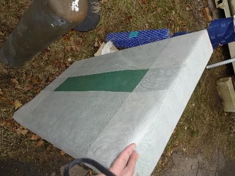
E3S Web of Conferences 172, 01001 (2020)                                                                   https://doi.org/10.1051/ e3sconf/202017201001
NSB 2020

       Fig. 1, left. After making a turn around the pipe, the fabric               absorbing wick is wound around the batts in a single
       is led through the slit of the pipe-section, which can be                   continuous layer so that moisture transport will not get
       made of a diffusion open material such as mineral wool.                     interrupted. The wick is routed all the way around the
       The outside of the pipe section has an outer jacket of                      insulation batt from the side that will face the cold, solid
       vapour tight material, and a small piece of the fabric                      wall to the side that will be behind the interior wall
       should be led out of the pipe section to the ambient, where                 cladding, which will typically be gypsum board. A vapour
       it can be attached to the outer surface of the vapour tight                 retarder is placed between the wick and the insulation on
       jacket. The jacket keeps moisture ingress into the system                   the warm side of the insulation, and down the sides of the
       slow, but nevertheless, when moisture accumulates on the                    insulation batt, and has a diffusion resistance
       pipe, it will be absorbed by the fabric so it functions as a                Z = 200 GPa·s·m2/kg (sd = 36 m). To prevent leaks, the
       wick that transports the moisture to the outside of the pipe.               vapour retarder consists of a large rectangular piece where
       The principle has proven functional and is today a                          the corner joints are folded in and taped.
       commercial system [5]. There are variations of the
       system, which keep the wick away from frost if the pipe                     3 Laboratory tests
       temperature is below 0°C. It is also possible to put an extra
       jacket on the complete outside of the system to make it
       suitable for used in rooms where hygienic requirements                      3.1 Purpose
       do not permit the potentially wet fabric to be exposed.
                                                                                   The purpose of the experiments was to compare the
       These variations of the system are functional, too.
                                                                                   efficiency of the three insulation systems: calcium
           Inspired by the situation of interior insulation of outer
                                                                                   silicate, iQ-Therm, and HygInsu when mounted as
       wall systems, and the principle of HygroWick, we have
                                                                                   interior insulation on a cold brick wall. The experimental
       developed a system to keep interior insulation batts dry by
                                                                                   set-up was to determine the distribution of water content,
       using a wick that absorbs moisture from where it would
                                                                                   temperature, relative humidity and water vapour pressure
       potentially condensate and transports it back to the indoor
                                                                                   in the samples over time. This was done to assess whether
       environment. This paper describes the system including
                                                                                   the samples in equilibrium were able to actively remove
       both laboratory experiments and a field test in which
                                                                                   moisture as it accumulated.
       prototypes of the system have been tested. Both types of
       experiments are compared with two known interior
       systems: Monolithic calcium silicate boards and the                         3.2 Method
       system marketed as iQ-Therm [3]. For reference, the
       system described here in this paper is called “HygInsu”.                    The cold brick wall, on which the samples were placed,
       The laboratory test have been described in [6], and this                    was imitated by two kitchen refrigerators located in a
       work is explained in summary here in the paper.                             large climate chamber that established the indoor ambient
                                                                                   conditions. The drawing of an exploded view and a
                                                                                   picture of the front elevation of the setup are shown in Fig.
                                         Warm                          Cold        2. The refrigerator doors were replaced with sheet metal
                                         side                           side
                                                                                   plate, which on the outside was insulated with foam
                                                                                   rubber insulation. Square holes were cut in the rubber
                                                                                   insulation in which the interior insulation samples would
                                                                                   fit. Thus, the temperature difference over the samples and
                                                                                   the relative humidity, RH, in the room on the warm side
                                                                                   were kept constant throughout the experimental period.
                                                                                   The air in the climate chamber was kept constant at 23 ºC
        1. Fluid at below ambient                                                  and the humidity at 65% RH. The refrigerators were kept
           temperature                                                             a temperature of about 4 ºC, so that there would be a cold
        2. Cold pipe
        3. HygroWick fabric                                                        surface with a temperature below the ambient dew point.
        4. Mineral wool pipe section                                               The samples of the three selected insulation materials
                                          1. Mineral wool insulation
        5. Vapour retarder jacket
                                          2. HygroWick fabric
                                                                                   were placed in plexiglass boxes with interior dimensions
        6. Tape for attachment                                                     of 20 cm x 20 cm. The boxes were made of 5 mm
        7. Evaporation area               3. Vapour retarder
                                                                                   plexiglass and had an inside depth of 10 cm. The boxes
       Fig. 1 Sketch of the HygroWick system used on cold piping                   allowed that the samples could easily be removed from
       (left), and the principle of the HygInsu interior wall insulation           the cold plate for weighing at regular intervals, so changes
       system (right).                                                             in total water content could be followed.
                                                                                        The foam rubber insulation gave a spacing of 6 cm,
       2 Description of HygInsu                                                    between the plexiglass boxes. The foam rubber has a high
       HygInsu is a composite material consisting of an effective                  water vapour resistance factor (μ t 10,000) and good
       insulating stone wool product protected by a diffusion-                     insulation properties (O d 0.033 W/(m·K)), so the heat
       tight vapour barrier wrapped with a moisture-transporting                   flow through the samples would be practically one-
       fabric. Fig. 1, right, shows the composition of the                         dimensional perpendicular to the insulation plane.
       HygInsu system. When the system is installed on a wall,                          A fan was installed in each refrigerator to provide a
       the insulation plane is broken at every batt, thus creating                 uniform temperature distribution over the cold sheet metal
       slits that allow the wick to pass through. The capillary                    plate. This, unfortunately, was not achieved as effectively

                                                                               2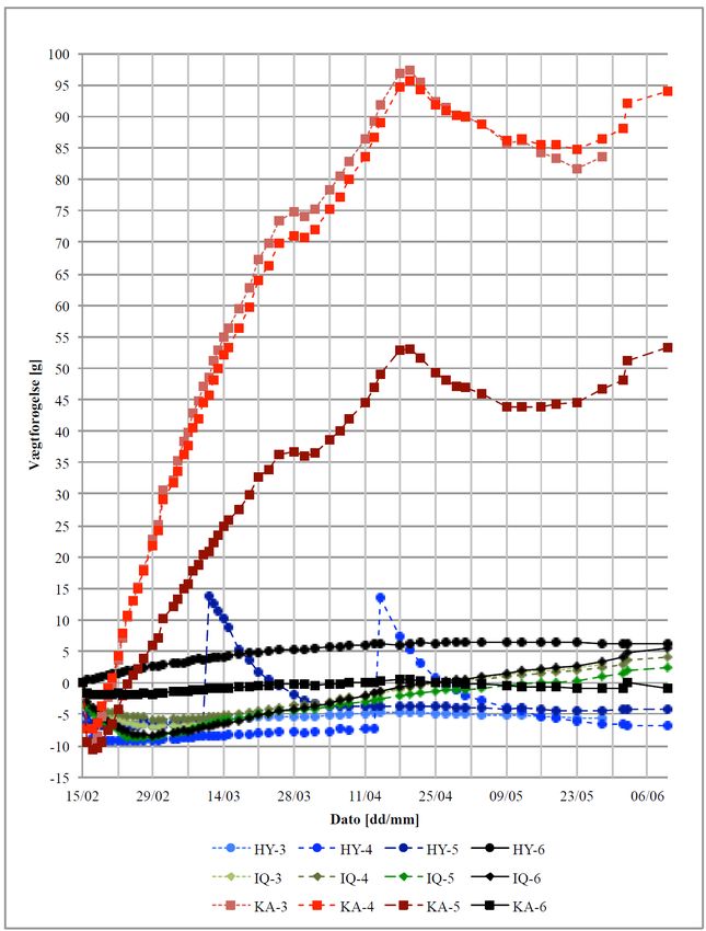
E3S Web of Conferences 172, 01001 (2020)                                                                          https://doi.org/10.1051/ e3sconf/202017201001
NSB 2020

       as expected, resulting in the temperature varying from 4.5               the manufacturers with a material thickness of 50 mm plus
       to 7 ºC. The surface was coldest 100 cm from the ground                  the recommended amounts of mortar and cladding.
       and warmest at the bottom. The temperature of the two                    Neither of the samples had a wall cover or surface
       refrigerators was calibrated to be reasonably equal, but                 treatment (such as gypsum board and paint) on the surface
       also this was not perfectly achieved, which could have                   that faced the climate chamber. 3 Sensirion SHT75
       some consequences on the comparability of the results.                   sensors that measure temperature and humidity were used
       Furthermore, the plexiglass boxes constituted                            in each of the wired samples. The sensors were placed at
       3-dimensional thermal bridges around the insulation                      depths 11, 25 and 39 mm from the front of the insulation
       samples, which there could not be compensated for.                       samples, and measurements took place at staggered
                                                                                positions horizontally at the centre of each sample and
                                                                                vertically at positions 50, 100 and 150 mm from the side.
                                                                                Cable holes were drilled so the sensors and their cabling
                                                                                did not disturb each other.

                                                                                               Table 1 Overview of the 18 samples and their naming.
                                                                                                  KA-1              IQ-1               HY-1

                                                                                  Small refrigerator
                                                                                                  Calc. silicate    iQ-Therm           HygInsu
                                                                                                  Sealed            Sealed             Sealed
                                                                                                  With sensors      With sensors       With sensors
                                                                                                  KA-2              IQ-2               HY-2
                                                                                                  Calc. silicate    iQ-Therm           HygInsu
                                                                                                  Open              Open               Open
                                                                                                  With sensors      With sensors       With sensors
                                                                                                  KA-3              IQ-3               HY-3
                                                        Refrigerator                              Calc. silicate    iQ-Therm           HygInsu
                                                        Sealing                                   Open              Open               Open
                        Plexiglass box                  Metal plate                               Weighted          Weighted           Weighted
                        Sample                          Rubber insulation                         KA-4              IQ-4               HY-4
                                                                                  Large refrigerator

                                                                                                  Calc. silicate    iQ-Therm           HygInsu
                                                                                                  Open              Open               Open
                                                                                                  Weighted          Weighted           Weighted
                                                                                                  KA-5              IQ-5               HY-5
                                                                                                  Calc. silicate    iQ-Therm           HygInsu
                                                                                                  Open              Open               Open
                                                                                                  Weighted          Weighted           Weighted
                                                                                                  KA-6              IQ-6               HY-6
                                                                                                  Calc. silicate    iQ-Therm           HygInsu
                                                                                                  Sealed            Sealed             Sealed
                                                                                                  Weighted          Weighted           Weighted

                                                                                    As can be seen in Table 1, six of the samples are
                                                                                marked as being sealed, rather than open. This means that
                                                                                the moisture transport in and out the samples has been
                                                                                prevented by sealing. The sealed samples were used as
                                                                                references to see how the materials would behave if they
                                                                                could not actively remove the moisture.

       Fig. 2 Exploded view and picture of test setup for refrigerator
       tests.

       3.2.1 Samples
       The two refrigerators had each their function in the
       experiment. Four samples of each insulation system were                  Fig. 3 A test box is wetted before start of the experiment and
       placed on the largest of the refrigerators. These 12                     edges are sealed with silicone caulking.
       samples were meant to be weighed. Two other samples of
       each material were put on the smallest of the refrigerators.                 Upon starting the experiment, some of the samples
       These 6 samples were not weighed because they were                       were wetted with water to kick-start the situation of a wet
       equipped with wired moisture and temperature sensors                     wall and see how this moisture would move. The amount
       and should be left undisturbed during the course of the                  of water added was equal to 80% of the water needed to
       measurements. Table 1 gives an overview of the 18                        saturate each material. Simulations in Delphin defined the
       sample types and their location. The sample names are                    saturation level. Thus, the calcium silicate wall samples
       marked in bold and will be referred to later. All samples                KA-3, KA-4 and KA-5 were wetted with 72 g of water
       were constructed according to the recommendations of                     injected with a syringe, see Fig. 3, left. 50 g was added to

                                                                            3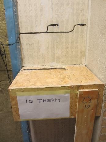
E3S Web of Conferences 172, 01001 (2020)                                                          https://doi.org/10.1051/ e3sconf/202017201001
NSB 2020

       the iQ-Therm wall samples IQ-3, IQ-4, IQ-5 and IQ-6,               middle of the sample, but as shown in            Fig. 4,
       and 10 g was added to the HygInsu wall samples HY-3,               it was removed with approximately one month when it got
       HY-4 and HY-5. The duration of the measuring period                in contact with the HygroWick. By capillary action, the
       was 116 days.                                                      wick has led the moisture to the warm surface of the
                                                                          assembly from where it could evaporate towards the
                                                                          climate chamber. The result shows that HygInsu has an
       3.3 Result and Analysis
                                                                          effective property for draining, which means that the
                                                                          assembly quickly attains a dry situation.
       3.3.1 Weighing results
                                  Fig. 4 shows all the weighing           3.3.2 Measurements from sensors
       results for the three materials. Each curve refers to one of
                                                                              Measurements were taken over a period of 112 days.
       the samples described in Table 1. The data points
                                                                          For each material type, a first graph presents the
       illustrated with squares (■) are for calcium silicate, where
                                                                          development over time. The subsequent two smaller
       open samples are red. Diamonds (♦) indicate the iQ-
                                                                          graphs show the moisture distributions within the samples
       Therm results, and all the open samples are green. The
                                                                          at the end of the experimental period for the open and
       results of the HygInsu samples are illustrated with circles
                                                                          sealed experiments, respectively.
       (●) and the open samples have blue colours. Sealed
       samples are all black, no matter the insulation type. The
                                                                               Calcium silicate
       weight gain is the difference between the measured
                                                                               The measurements for KA-1 (11 mm) show that the
       weight and the initial weight.
                                                                          relative humidity decreases during the first few weeks,
                                                                          while measurements for KA-1 (39 mm) increase. This
           Calcium silicate
                                                                          shows that moisture accumulates where it is coldest and
           As shown in           Fig. 4, the sealed calcium
                                                                          the water evaporates from the free surface to the ambient
       silicate sample does not gain weight at all because of its
                                                                          climate chamber. The results of the middle sensor in the
       diffusion-tight paint. However, the open samples quickly
                                                                          open sample KA-1 (25 mm) show that after it has dropped
       gain weight, and after 10 weeks there is a maximum
                                                                          in the first few days, it begins to rise and after two months
       increase of 97 grams. After this peak, the weight change
                                                                          it is at the same level like the rear sensor. This means that
       becomes more subtle, indicating that an equilibrium with
                                                                          the condensation on the cold side has gradually spread
       the humidity of the ambient climate chamber has been
                                                                          further towards the warm side until it finally reached the
       attained. Common for all the initially soaked samples is
                                                                          sensor in the centre of the sample. The striking increase in
       that they lose much of the liquid added at the start of the
                                                                          relative humidity also corresponds to the large weight
       experiment.
                                                                          gain, which was seen in Fig. 4.
                                                                               The measurements for the sealed sample KA-2 show
           iQ-Therm
                                                                          almost as high relative humidity as the open. The reason
           The first thing to note when considering the weighing
                                                                          could be due to water that has penetrated through the
       results for iQ-Therm in Fig. 4 is that the weight gain is
                                                                          drilled holes in the side of the sample through which the
       much lower than that of calcium silicate. This is caused
                                                                          sensor wires were led.
       by the calcium silicate being very hydrophilic, while the
       polyurethane core of iQ-Therm is water resistant with a
                                                                              iQ-Therm
       closed pore system, meaning that the water is located
                                                                              The open iQ-Therm sample (IQ-1) becomes more
       primarily in the adhesive mortar near the cold surface. The
                                                                          water filled than the sealed (IQ-2), especially in the two
       graphs also show that all four samples have had the same
                                                                          measuring points closest to the cold surface. This can be
       constant weight gain since week 2 without signs of
                                                                          seen in Fig. 6 where the points for the relative humidity
       change. The last measurement is therefore also the
                                                                          graph at a distance of 2.5 cm and 3.9 cm from the inner
       highest, which means that there is no indication that the
                                                                          surface as well is higher.
       iQ-Therm tests have come in equilibrium with the indoor
                                                                              The graph of the vapour pressure for IQ-1 makes an
       climate.
                                                                          unnatural kink in Fig. 6, lower left. This is because of the
                                                                          low values in relative humidity measured in IQ-1 (11
           HygInsu
                                                                          mm). Since the sensors only measure relative humidity
           Due to the diffusion-tight vapour barrier that closes
                                                                          and temperature, the vapour pressure is determined from
       tightly around the mineral wool, the samples do not gain
       much in weight. For this reason, it would take long time           p = M·ps. The relative humidity at this point may be a
       before the wick would become wet enough to make the                result of the position of a sensor close to the capillary
       liquid transporting properties of HygInsu influential. To          active channels.
       determine whether the HygInsu samples have a liquid                    HygInsu
       moisture transporting property, the samples HY-5 and                   There is a clear linear correspondence between the
       HY-4 were therefore wetted with some extra 20 grams of             relative humidity and all of the three points in the mineral
       liquid during the experimental period. The water was               wool. This linearity is due to the fact that the material is
       supplied by means of a thin syringe and the hole in the            homogeneous and unlike the other materials, the mineral
       vapour barrier subsequently sealed with tape. The 20               wool has no capillary active or moisture absorbing
       grams of water was supplied at a depth of 2.5 cm in the            properties. Therefore, there is no gradient in vapour

                                                                      4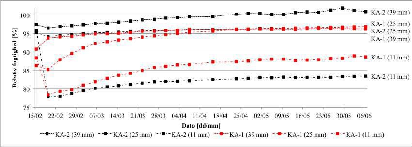
E3S Web of Conferences 172, 01001 (2020)                                                           https://doi.org/10.1051/ e3sconf/202017201001
NSB 2020

       pressure, and almost no change over time and no fluid                immediately apparent from these results. A probable
       front. Naturally, the relative humidity is highest near the          reason could be that the liquid will be localized in a thin
       cold surface.                                                        layer at the cold surface rather than within the mineral
           The sealed sample should contain more moisture as it             wool, and thus will not influence even the coldest sensor.
       has no possibility to actively drain it, but this is not
                    Weight gain, g

                                                                   Date [dd/mm]

                  Fig. 4 Results from weighing of all samples from the large refrigerator.

                                                                            site of the Technical University of Denmark, 15 km north
       4 Field test                                                         of Copenhagen city centre. The facility was comprised of
                                                                            two 40“ reefer containers that were positioned on the test
       4.1 Description of the set-up                                        site such that one of the long-sided wall surfaces faced
                                                                            north-east (and the opposite side faced south-west), and
           A field test of a full-scale wall with HygInsu as                1 m wide x 2 m tall openings were cut in the insulated
       interior insulation was carried out in an outdoor field test         steel walls in which some solid 1½ stone (34.8 cm) walls

                                                                        5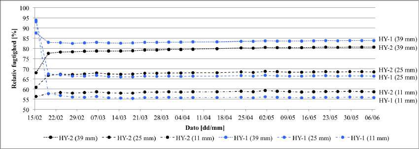
E3S Web of Conferences 172, 01001 (2020) https://doi.org/10.1051/ e3sconf/202017201001
NSB 2020
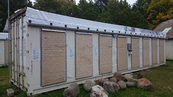
were bricked up. Each façade made room for 8 such wall Fig. 7. Sensor results of the evolution and distribution of
mock-ups. See the exterior set-up on Fig. 8. moisture content in HygInsu. Significance of line types like in
Fig. 5.
Relative humidity [%]
Vapour pressure [Pa]
Vapour pressure [Pa]
Relative humidity [%]
Relative humidity [%]
Fig. 8. South-west façade of reefer container used as facility
for tests of hygrothermal conditions in interior insulated
Distance from warm surface [cm] Distance from warm surface [cm]
masonry walls.
Fig. 5 Sensor results of the evolution and distribution of
moisture content in calcium silicate. The lower graphs show
moisture distributions after 112 days with relative humidity
(·····), vapour pressure (───), and saturation vapour pressure
(------). Lower graphs are for the open specimen on the left and
sealed specimen on the right.
Relative humidity [%]
Vapour pressure [Pa]
Relative humidity [%]
Vapour pressure [Pa]
Relative humidity [%]
Distance from warm surface [cm] Distance from warm surface [cm]
Fig. 6. Sensor results of the evolution and distribution of
moisture content in iQ-Therm. Horizontal gray and red lines
merely symbolize the calciumsilicate channels that pentrate the
material, and are not to be seen as indicators of particular
humidity values. Significance of line types like in Fig. 5. Fig. 9. Vertical cross-section of wall with interior insulation
and location of sensors. Measuring positions 8 and 9 are
duplicates of positions 3 and 4, but are placed at the separation
Relative humidity [%]
wall, which can be seen on the right-hand side of the photo.
The photo shows the wall with iQ-Therm insulation in place
before mounting the interior gypsum wall cladding.
The masonry was covered on the inside with 10 mm
lime render. Around mid-height of each wall mock-up
was positioned a wooden beam of 17.5x17.5 cm cross
section, which extended about half a meter into the room
Vapour pressure [Pa]
Vapour pressure [Pa]
of the container and 10 cm into the masonry. The beam
Relative humidity [%]
Relative humidity [%]
rested on a horizontal, longitudinal 10x10 cm wooden
lath, which was inserted in a recess in the masonry. A
15 mm OSB board over and under the part of the beam
that stretched into the room mimicked floor and ceiling in
a floor separation, and it was partly filled with a 100 mm
Distance from warm surface [cm] Distance from warm surface [cm] mineral wool batt. An indoor separation wall of half stone
brick (10.8 cm plus 10 mm lime render on either side) was
6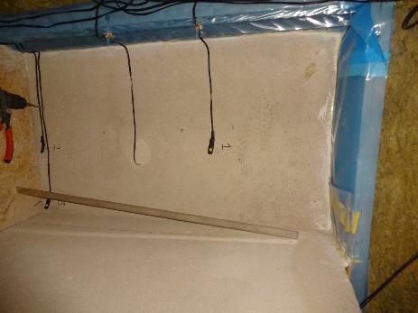
E3S Web of Conferences 172, 01001 (2020)                                                            https://doi.org/10.1051/ e3sconf/202017201001
NSB 2020

       positioned in full wall height next to the wooden beam,             stone wool outfitted with the HygInsu system. In addition
       see the picture in Fig. 9 (right). 2 x 12 mm gypsum board           to the HYT sensor, which measures temperature and RH
       was used as interior cladding of the insulation. No vapour          within the wall rendering, three HYT sensors in different
       retarder or interior paint was used in the walls described          lateral and vertical positions close to the centre and
       in this paper. Each wall was instrumented with 9                    perimeter of the insulation batt measured temperature and
       HYT 221 sensors (from Innovative Sensor Technology,                 RH at the interface between the HygInsu system’s
       IST AG) that measured temperature and relative humidity             Hygrowick glass fibre felt at the cold, outer side of the
       with hourly intervals in two positions in the masonry, in           insulation. Like in other walls, a HYT sensor measured
       the lime render, on the warm side of the insulation, at two         temperature and RH in the interface between interior
       positions in the wooden beam, and on the cold side of the           gypsum cladding and the insulation system close to the
       wooden lath. A weather station measured the outdoor                 centre of the insulation.
       weather conditions and indoor temperature and relative
       humidity was logged with hourly intervals. A vertical
                                                                           4.3 Results
       cross-section through the set-up with indication of sensor
       positions is shown in Fig. 9 (left). Further description of         The results are illustrated by means of the measured
       the facility, its measuring system, and the other walls can         relative humidity in some of the positions, which are
       be found in the PhD-thesis of Tommy Odgaard [2].                    deemed to be most interesting and also most likely
           A wall, which was insulated on the interior side with           influenced by the performance of the insulation system.
       the HygInsu system (of thickness 100 mm) occupied one               These are:
       of the places facing north-east. The instrumented wall              x Measuring position 3, in lime render on the inside of
       cavity that was insulated with the HygInsu system was               the masonry/outside of the insulation system and its glue
       positioned over beam height and had width 530 mm and                mortar. Three extra measurement positions for HygInsu at
       height 952 mm. The HygInsu sample fit tight to the sides            the interface between wick and render (Fig. 11).
       of the cavity.                                                      x Measuring position 4, in interface between interior
           Along the same façade were also two walls, which                gypsum cladding and inside surface of insulation (Fig. 12)
       were insulated with calcium silicate (100 mm) and iQ-               x Measuring position 5, at the cold, exterior side of the
       Therm (80 mm), respectively. The iQ-Therm and calcium               wooden lath (Fig. 13)
       silicate insulation systems used a dedicated glue mortar to
                                                                           x Measuring position 6, in wooden beam end (Fig. 14).
       adhere the insulation to the lime render, and these two
       walls did not have gypsum boards as interior cladding.

                                                                           Fig. 11. Relative humidity in lime render on the inside of the
                                                                           masonry, and for HygInsu in the positions of the wick/render
       Fig. 10. Left: Insulation batt with HygInsu system before
                                                                           interface (measuring position 3).
       installation. Right: Place reserved for HygInsu system behind
       interior rendering of the masonry with sensors to measure
       humidity at the wick/render interface.

       4.2 Experimental conditions
       The interior of the container was heated with electric
       heaters to around 20°C, and a humidifier kept the
       humidity at the relatively high level of around 60% RH
       year round (although the humidifier was off for a few
       months in the winter 2018/19). Fans stirred the air so the
       interior conditions were well mixed. A picture of the
       containers with their masonry wall is shown in Fig. 8. The
       interior insulation system with HygInsu was mounted in
       November 2016, whereas the walls with calcium silicate
       and iQ-Therm had been installed and in operation since
       May 2015. Fig. 10 shows a picture of an insulation batt of

                                                                       7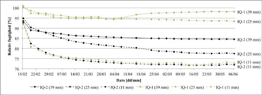
E3S Web of Conferences 172, 01001 (2020)                                                              https://doi.org/10.1051/ e3sconf/202017201001
NSB 2020

           Fig. 12. Relative humidity in the indoor environment,                  iQ-Therm performed better in the laboratory tests with
       and at interface between interior cladding and inside                  only slow changes of moisture content and relative
       surface of insulation (measuring position 4).                          humidity, and tendencies that could go both up and down
                                                                              in moisture content during the measurement period. RH
                                                                              was around 90 % on the cold side.
                                                                                  HygInsu demonstrated a very good capability in the
                                                                              laboratory tests to drain surplus moisture from the
                                                                              assembly, and the relative humidity measured in the
                                                                              material tended to be a little lower than what was
                                                                              measured for iQ-Therm, with RH topping at around 85%
                                                                              among the measured positions. The system demonstrated
                                                                              at two occasions in the laboratory test that it was able
                                                                              within a month to drain surplus moisture that was added
                                                                              to the assembly. Thus, the system may have some
                                                                              resiliency to dry out moisture that in a practical situation
                                                                              has inadvertently entered the construction.
                                                                                  In the field tests, only relative humidity was measured
                                                                              as an indicator for moisture, but this was done in several
       Fig. 13. Relative humidity at cold, exterior side of wooden lath       positions in the tested brick walls with interior insulation.
       (measuring position 5).                                                At the render on the cold side of the insulation system, the
                                                                              relative humidity was critically high for calcium silicate
                                                                              and iQ-Therm with values mostly above 90% or at
                                                                              saturation for calcium silicate, and around or above 90 %
                                                                              for iQ-Therm. Among the wooden members, the wooden
                                                                              lath had critical relative humidity with the iQ-Therm
                                                                              system as RH was mostly above 90%. The beam end
                                                                              performed better with RH around 80% or lower.
                                                                                  With calcium silicate, both the wooden lath and the
                                                                              beam end had RH mostly between 80 and 90 %, which
                                                                              can be assessed as a high, but perhaps not critical level.
                                                                                  A short summary of the humidity conditions seen in
                                                                              the field test with the HygInsu system is that the humidity
                                                                              was mostly at the same or slightly lower levels than what
                                                                              was seen in walls with the two other insulation systems.
                                                                              Particularly at the render outside of the insulation, there
                                                                              was a tendency for the relative humidity to be some 10%
       Fig. 14. Relative humidity in wooden beam end (measuring
       position 6).                                                           RH lower with HygInsu than with the two other systems.
                                                                                  A future study should use the measured data together
                                                                              with a recognized mould growth model to analyse the risk
       5 Discussion and Conclusion                                            of fungal activity on the measured positions.
       The paper has demonstrated some initial experiments of                     Altogether, while it has been sad to see some rather
       laboratory and outdoor field test performance of                       high humidity values in many of the performed tests, it
       prototypes of a new thermal insulation composite, named                has been encouraging to see the equal or somewhat better
       HygInsu, which is comprised of mineral wool convoluted                 performance of the new insulation principle with
       in a capillary active fabric of glass fibre felt. The capillary        HygInsu. However, it must be stated that these have been
       active glass fibre felt makes it possible to remove the high           only some first tests of prototypical examples of the
       moisture content that may usually occur in the critical                system, and more testing and assessment shall be needed.
       interface between insulation and the inside of a solid brick
       wall. The new system has been tested side by side with                 References
       commercial products of calcium silicate and a
       polyurethane product with capillary active calcium                     1. RIBuild, Robust Internal Thermal Insulation of
       silicate channels (iQ-Therm). The experiments have                        Historic Buildings, www.ribuild.eu/ (2020)
       shown, both in the laboratory tests that lasted almost four            2. T. Odgaard, Challenges when retrofitting multi-storey
       months and in the three-year field study, that the commer-                buildings consisting of solid masonry facades and
       cial systems may have critically high moisture levels.                    embedded wood with interior thermal insulation. PhD
           In the case of laboratory tests with calcium silicate, the            thesis, Technical University of Denmark (2019)
       moisture content was steadily increasing for a couple of               3. iQ-Therm, www.remmers.com (2020)
       months and then reached a situation with steady high                   4. V. Koverdynsky, V. Korsgaard and C. Rode. The
       moisture content. Relative humidity reached saturation                    Wick-Concept for Thermal Insulation of Cold Piping.
       (100% RH) for the coldest half of the material.                           J. Bldg. Phys. 29, 313-327. (2006)

                                                                          8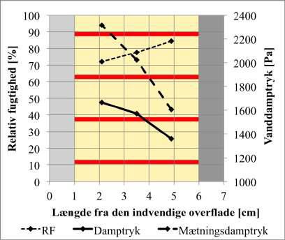
E3S Web of Conferences 172, 01001 (2020)                              https://doi.org/10.1051/ e3sconf/202017201001
NSB 2020

       5. Isover. Climcover. https://www.isover.dk/products/
          climcover-lamella-hygrowick-hygrowick-
          lamelmaatter. (2020)
       6. N.K. Friis, C. Pedersen, Environmental impact and
          moisture transporting properties of materials used as
          internal extra insulation. Bachelor thesis, Technical
          University of Denmark (2016)

                                                                  9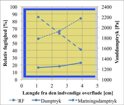
You can also read