User Manual LVRSys - 3-phase Systems Low-Voltage-Regulation-System - Indoor - A. Eberle
←
→
Page content transcription
If your browser does not render page correctly, please read the page content below
User Manual
 LVRSys™ - 3-phase Systems
Low-Voltage-Regulation-System™
 Indoor

 Systems of the series: 180.1000.2xxx
We take care of it.

Content
1. User guidance ................................................................................................................ 1
1.1 Target group............................................................................................................................. 1
1.2 Warnings .................................................................................................................................. 1
1.3 Tips ........................................................................................................................................... 1
1.4 Other symbols .......................................................................................................................... 2
1.5 Applicable documentation ....................................................................................................... 2
1.6 Keeping .................................................................................................................................... 2
2. Scope of Delivery ........................................................................................................... 3
3. Safety instructions ......................................................................................................... 3
4. Technical Data ............................................................................................................... 4
5. Intended use .................................................................................................................. 5
6. Description and Principle of Operation ........................................................................... 5
6.1 Principle of Operation .............................................................................................................. 5
6.2 Operating behaviour in the low-voltage grid........................................................................... 7
6.3 Voltage drop with load............................................................................................................. 8
6.4 Voltage boost with generator (e. g. PV feeder) ....................................................................... 9
7. Commissioning and Decommissioning LVRSys™ .............................................................10
7.1 Indicator lamps & system switch ........................................................................................... 10
7.2 Commissioning and decommissioning LVRSys™ .................................................................... 10
7.3 Check that there is no voltage present .................................................................................. 12
7.4 Operation of circuit breakers and switch-disconnectors ....................................................... 12
 Operation of systems with circuit breakers ........................................................................... 12
 Operation of systems with LV fuse-switch-disconnectors ..................................................... 13
8. Operation/Operation regulator .....................................................................................14
8.1 Indicator lamps/System switches .......................................................................................... 14
8.2 Indicator lamps & switch service – CPU board (A7)............................................................... 14
8.3 Indicator lamps – Control cabinet.......................................................................................... 15
8.4 Switches ................................................................................................................................. 15
8.5 Boot process .......................................................................................................................... 16
8.6 Menu navigation .................................................................................................................... 16
8.7 Automatic mode .................................................................................................................... 17
8.8 Manual mode ......................................................................................................................... 17
8.9 Overview display .................................................................................................................... 18
8.10 Parameters ............................................................................................................................. 19
 Set point ................................................................................................................................. 20

Content
Tolerance band + and tolerance band - ..................................................................................20
 Reaction time ..........................................................................................................................21
 Impedance ..............................................................................................................................22
 Balancing (Bal. active) – from FW 12.00.05 ............................................................................23
 Overvoltage warning – from FW 12.00.06..............................................................................24
 Undervoltage warning – from FW 12.00.06 ...........................................................................24
8.11 Setup .......................................................................................................................................25
 Communication.......................................................................................................................25
 Security ...................................................................................................................................25
 Date.........................................................................................................................................25
 Time ........................................................................................................................................25
 Language .................................................................................................................................25
8.12 Device Info ..............................................................................................................................26
 USB ..........................................................................................................................................26
 Firmware update ....................................................................................................................26
 Logbook...................................................................................................................................27
 Firmware-Version ...................................................................................................................34
 LOG ERR ..................................................................................................................................34
 Type number ...........................................................................................................................35
8.13 Factory settings .......................................................................................................................35
 Step width ...............................................................................................................................36
 Network frequency .................................................................................................................36
 CT ratio (current transformer ratio) .......................................................................................36
 Resetting the indicator ...........................................................................................................36
 Clear statistics .........................................................................................................................37
9. Communication ............................................................................................................ 38
9.1 Ethernet ..................................................................................................................................38
10. IT-Security .................................................................................................................... 39
11. External devices & modifications .................................................................................. 40
11.1 External devices ......................................................................................................................40
12. Servicing/Cleaning/Spare parts ..................................................................................... 40
13. Standards and Laws (all based on European standards) ................................................. 40
14. Disassembly & disposal ................................................................................................ 41
15. Warranty ..................................................................................................................... 41

 Content

1. User guidance
 This User Manual is a summary of the information needed for the installation, commission-
 ing and operation of the low-voltage regulator.
 Read the User Manual in its entirety and do not use the product unless you have under-
 stood the User Manual.

1.1 Target group
 The User Manual is intended for skilled technicians as well trained and certified operators.
 The contents of this User Manual must be accessible to people tasked with the installation
 and operation of the system.

1.2 Warnings
 Structure of the warnings
 Warnings are structured as follows:
 SIGNAL WORD Nature and source of the danger.
 Consequences of non-compliance.
 Actions to avoid the danger.

 Types of warnings
 Warnings are distinguished by the type of danger they are warning against:
 DANGER! Warns of imminent danger that can result in death or serious injuries
 if not avoided.

 WARNING! Warns of a potentially dangerous situation that can result in death or
 serious injuries when not avoided.

 CAUTION! Warns of a potentially dangerous situation that can result in
 fairly serious or minor injuries when not avoided.

 NOTICE: Warns of a potentially dangerous situation that if not avoided
 could result in material or environmental damage.

1.3 Tips
 Tips on the appropriate device use and recommendations.

 Page 1
We take care of it. 1.4 Other symbols Instructions Structure of the instructions: Instructions for an action. Indication of an outcome, if necessary. Lists Structure of unnumbered lists: 0 List level 1 – List level 2 Structure of numbered lists: 1) List level 1 2) List level 1 1. List level 2 2. List level 2 1.5 Applicable documentation For the safe and correct use of the product, observe the additional documentation that is delivered with the system as well as the relevant standards and laws. 1.6 Keeping Keep the user manual, including the supplied documentation, readily accessible near the system. Page 2
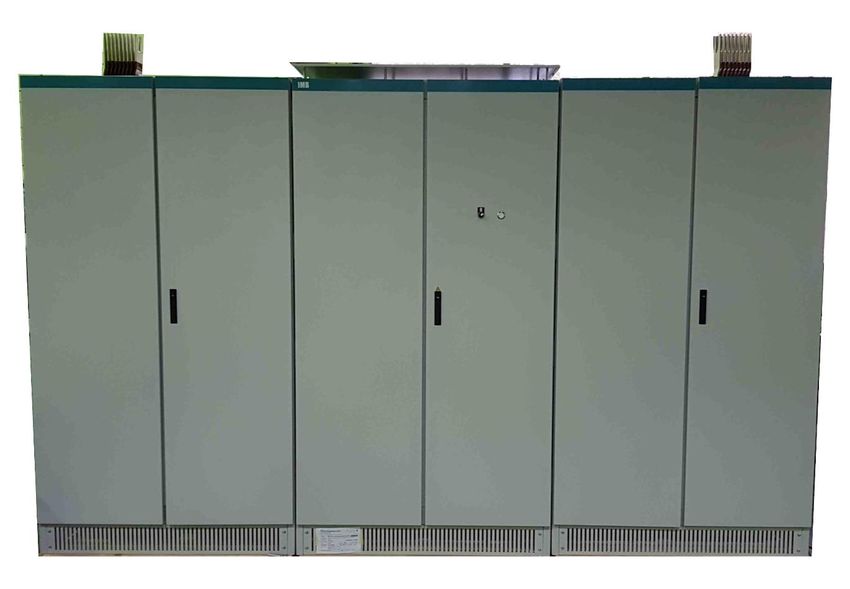
2. Scope of Delivery The main components and documents are: 0 Control cabinet left (z. B. 180.1000.21xxL) 0 Control cabinet central incl. LVRSys™ control unit (z. B. 180.1000.21xxM) 0 Control cabinet right (z. B. 180.1000.21xxR) 0 LVRSys™ user manual 0 LVRSys™ mounting instructions 0 Circuit diagram of the LVRSys™ control cabinet 0 LVRSys™ test certificate 3. Safety instructions Observe the operating instructions Always keep the operating instructions with the unit. Make sure that the device is never operated in a damaged or compromised condition. Make sure that only specialized personnel operate the unit. The device must be connected according to the manufacturer’s installation instructions. Make sure that the device is never operated beyond its stated ratings (refer chapter 4, Technical Data) Do not operate the unit in any hazardous environment where explosive gases, dust or fumes occur. Ensure that protective covers are always in place and are functional Ensure that the five safety regulations according to DIN VDE 0105 are always observed. Clean the appliance only with commercially available detergents. Page 3
We take care of it.

4. Technical Data
 Rated data
 Rated voltage 415 V / 240 V ±20 % (L-L/LE)
 Rated current 3-phase 2,26 kA
 Rated frequency 50 Hz
 Efficiency 99.4 % – 99.8 %
 Maximum regulation time 30 ms
 Regulation area ± 12 % from UN in 9 steps á 3 %
 Ambient temperature 0 °C to + 40 °C
 Maximum permissible air temperature 60 °C
 in the cabinet
 Height of installation (NN) < 1000 m
 Protection class IP21
 Maximum current consumption sec- 200 mA (220 V DC)
 ondary electronics
 Short-circuit impedance ca. 0,3 %
 Cooling passive (convection via control cabinet case)
 Grounding system TN-C, common PEN-conductor
 In cabine insert insulated PEN-conductor/line bar,
 additionally PE-line bar
 Connection Input Connection from above for line bar Sivacon 8PS –
 System LR, line bar with 3 phases, PEN.
 Connection output Connection from above for line bar Sivacon 8PS –
 System LR, line bar with 3 phases, PEN.

 Limits
 Rated impulse voltage 6 kV
 Rated short-time current resistance ( 1 s) 40 kA

 Dimensions and weight Dimensions cabinet B/T/H Weight
 Cabinet left 120 cm/ 90cm / 220 cm 1200 kg
 Cabinet central 120 cm/ 90cm / 220 cm 1300 kg
 Cabinet right 120 cm/ 90cm / 220 cm 1200 kg
 3 cabinet-combination 360 cm/ 90cm / 220 cm 3700 kg

 Fulfilled guidelines
 EMC Immunity DIN EN 61000-6-1
 EMC emissions DIN EN 61000-6-3
 Installation instructions DIN EN 61439-1/5
 Low voltage directive 2014/35/EU

Page 4
5. Intended use
 This product is designed exclusively to regulate voltage at the low voltage level (400V L-L
 and special applications 230 V L-L).

6. Description and Principle of Operation
6.1 Principle of Operation
 The LVRSys™ regulator concept is based on a linear regulator. By coupling and uncoupling
 two transformers with a selected transfer ratio, the output voltage can be regulated in sev-
 eral (e.g. 9) steps. This technique is also referred to as Buck/Boost transformers
 The maximum control range depends on the model of LVRSys (e.g. from ±6% up to ±24%).
 The switching of the transformers is controlled by thyristors. The regulation steps are deter-
 mined by the thyristors' various switching settings.

 Step Transformer 9% Transformer 3%
 12% 9% 3%
 9% 9% 0%
 6% 9% -3%
 3% 0% 3%
 0% 0% 0%
 -3% 0% -3%
 -6% -9% 3%
 -9% -9% 0%
 -12% -9% -3%
 Table 6-1 Generation of the voltage levels in steps, example for 12% arrangement

 The control signals for the thyristors are generated by driver circuits that switch them intel-
 ligently. By monitoring the magnetic flux in the transformers, the transformers can be
 switched without any voltage dips or current increases occurring or harmonics being gener-
 ated.

 The step change required is output by the controller. The controller can determine the step
 based on the bus bar voltage or the output currents.

 All three phases are regulated independently of one another. This greatly helps improve the
 symmetry – balancing of the 3 phases of the LV Network.

 In the event of a failure the safety contactor activates automatically. This ensures that the
 transformers are bridged out and as such the low-voltage grid will operate unregulated.

 Page 5
We take care of it.

 Figure 6-1 Single-phase functional diagram

 Trafo TAx.1 Additional transformer 1
 Trafo TAx.2 Additional transformer 2
 FC8.x, FC9.x Fuse
 KFx.1/KFx.2 Safety contactor
 R Switching resistor
 QA1.y-QA5xz Thyristors
 WCLINx zu PEN Unregulated input voltage
 WCLOUTx zu PEN Regulated output voltage
 Table 6-2 Explanation of the abbreviations

Page 6
6.2 Operating behaviour in the low-voltage grid
 The low-voltage regulation systems are designed for a long, robust use in the low-voltage
 grid. In the following, grid scenarios are compared with the behaviour of the low voltage
 regulation systems.

 Event reaction LVRSys™
 Short circuit Ph1 Fuse blow off Ph1
 Automatic bypass activated for all phases
 Automatic restart of the controller after replacing the fuse
 Short circuit Fuse blow off Ph2/Ph3
 Ph2/Ph3 Automatic bypass activated for all phases.
 Automatic operation mode of the controller after replac-
 ing the fuse
 Lightning strike Lightning protection activated
 All phases Only after several lightning strikes releases lightning rod
 and separates the control system from the main voltage.
 Automatic restart of the controller after replacement of
 the lightning arrestor module
 Voltage drop Phase No reaction of the controller up to 100 V residual voltage.
 1 Below 100 V residual voltage, the controller goes into au-
 tomatic bypass mode
 When the voltage returns, the controller automatically
 switches to operating mode
 Voltage drop Phase No reaction of the controller to 5% residual voltage. Below
 2/3 5% residual voltage for> 20 ms, the controller goes into au-
 tomatic bypass mode. After the voltage has returned to
 normal, the controller automatically switches to operating
 mode
 Overvoltage Phase No reaction of the controller up to 170% residual voltage.
 1/2/3 Over 170% residual voltage for> 30 ms, the controller goes
 into automatic bypass mode. After the voltage has re-
 turned to normal, the controller automatically switches to
 operating mode
 Harmonics harmonics have no influence on the controller
 The Controller has no influence on the harmonics.
 Flicker Flicker does not affect the controller
 The controller does not affect the ripple flicker values.
 Ripple control sig- Ripple control signal has no influence on the controller
 nal Controller has no influence on ripple control signals
 Figure 6-2 System reaction after events

 Page 7
We take care of it.

6.3 Voltage drop with load

 Figure 6-3 Low voltage grid with voltage drop along the cable

 Figure 6-4 Low voltage grid with voltage drop along the cable (example)

 Figure 6-5 Low voltage grid with voltage drop along the cable regulated through LVRSys
 [Simulation Screenshots made with Neplan®].

Page 8
6.4 Voltage boost with generator (e. g. PV feeder)

 Figure 6-6 Low voltage grid with voltage boost along the cable

 Figure 6-7 Low voltage grid with voltage boost along the cable (example)

 Figure 6-8 Low voltage grid with voltage boost along the cable regulated through LVRSys
 [Simulation Screenshots made with Neplan®].

 Page 9
We take care of it. 7. Commissioning and Decommissioning LVRSys™ 7.1 Indicator lamps & system switch Figure 7-1 Indicator lamps and system switch Figure 7-2 Switch position 7.2 Commissioning and decommissioning LVRSys™ For operating the LVRSysIN, LVRSysOUT and BYPASS switching elements, observe chapter. The starting position is: 0 Closed BYPASS (F3). 0 Opened input (F1 / LVRSys-IN). 0 Opened output (F5 / LVRSys-OUT). 0 The controller is in the OFF state. DANGER! Danger of electric shock! Ensure that the LVRSys™ is only operated and commissioned by quali- fied electricians or persons trained in electrical engineering in accordance with VDE 0105-100 or certified with respect to the local wiring and safety regulations applicable in your country. Never open NH-switch disconnectors/-isolators/circuit breakers partially Only operate the NH-switch disconnectors/-isolators/circuit breakers by using the handle CAUTION! Destruction of components due to overload! Only switch the LVRSys™ ON or OFF according to the sequence of actions described below. Never use BYPASS-separation terminals while the system is in CONTROL - mode. Page 10
Commissioning LVRSys™ Decommissioning LVRSys™ BYPASS BYPASS - CONTROL - CONTROL - BYPASS - mode mode mode mode Sequence: Sequence: 1 . Close LVRSys-IN 1 . Set the systems switch to the OFF posi- (with knives/fuses). tion. 2 . Close LVRSys-OUT Wait until secondary electronics are de-energised. (with knives/fuses). (Display goes out after approx. 10 s). 3 . Open BYPASS 2 . Close BYPASS (with knives). (remove knives). 3 . Open LVRSys OUT (remove 4 . Set the system switch to the ON posi- knives/fuses). tion. 4 . Open LVRSys IN (remove knives/fuses). The regulator starts up automatically. The LVRSys™ is completely discon- LVRSys™ is active. nected from the network. The local network is regulated by the BYPASS is active. LVRSys™. The network is supplied via the BYPASS. Check that there is no voltage present (Chap. 7.3) LVRSys™ in BYPASS - mode LVRSys™ in CONTROL - mode System switch System switch CONTROL - OFF ON mode Connection Connection from from Transformer Transformer LVRSys IN LVRSys IN LVRSys™ BYPASS LVRSys™ BYPASS Regulation Regulation LVRSys OUT LVRSys OUT Connection Connection towards towards Load Load Figure 7-3 Circuit principle Bypass and operation Page 11
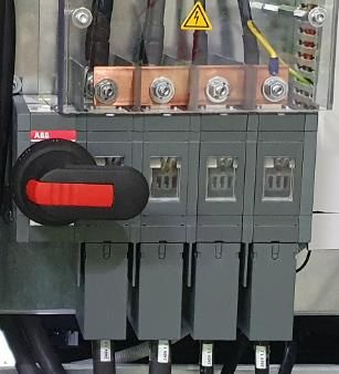
We take care of it. 7.3 Check that there is no voltage present DANGER! Danger of electric shock! Check that there is no voltage on the system input. Check that there is no voltage on the system output. Only measure with fused measuring devices with overvoltage category IV. 0 Check there is no voltage right after fuse .FC8.1 (left cabinet ). 0 Check there is no voltage right after fuse .FC8.2 (central cabinet). 0 Check there is no voltage right after fuse .FC8.3 (right cabinet). 0 System switch OFF 0 Check there is no voltage right after fuse .FC7.1 (central cabinet / control unit). 7.4 Operation of circuit breakers and switch-disconnectors Operation of systems with circuit breakers When switching the devices, the following must be observed: Ensure that commissioning, decommissioning and operation are only carried out by qualified electricians or persons trained in electrical engineering in accordance with VDE 0105-100 or certified with respect to the local wiring and safety regulations appli- cable in your country. Make sure that sequence of switching described in the short operating instruction (lo- cated on the inner surface of the door) is being followed. Figure 7-4 Connection and BYPASS function Page 12
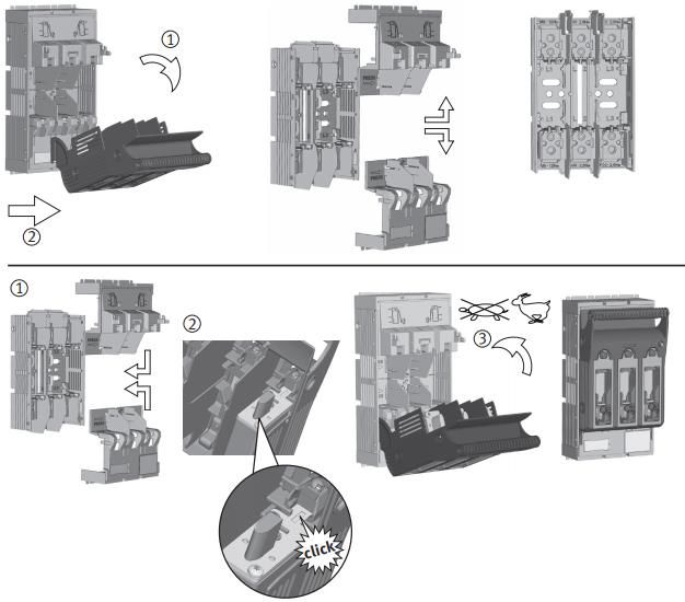
Operation of systems with LV fuse-switch-disconnectors DANGER! Risk of fatal injury from electric shock! Never partially open LV fuse switch disconnectors Operate the LV fuse switch disconnectors on the handle. Its intended that LV fuses are only used by qualified electricians or persons trained in elec- trical engineering e.g.: IEC 60269-2 or certified with respect to the local wiring and safety regulations applicable in your country. When switching the devices, the following must be observed: Ensure that commissioning, decommissioning and operation are only carried out by qualified electricians or persons trained in electrical engineering in accordance with VDE 0105-100 or certified with respect to the local wiring and safety regulations appli- cable in your country. Ensure that only fuse links with silver-plated knives or silver-plated disconnection knives are used. Only operate LV fuse switch disconnectors by the operating handle. Always operate LV fuse switch disconnectors quickly. Figure 7-5 Operation fuse switch disconnectors Page 13
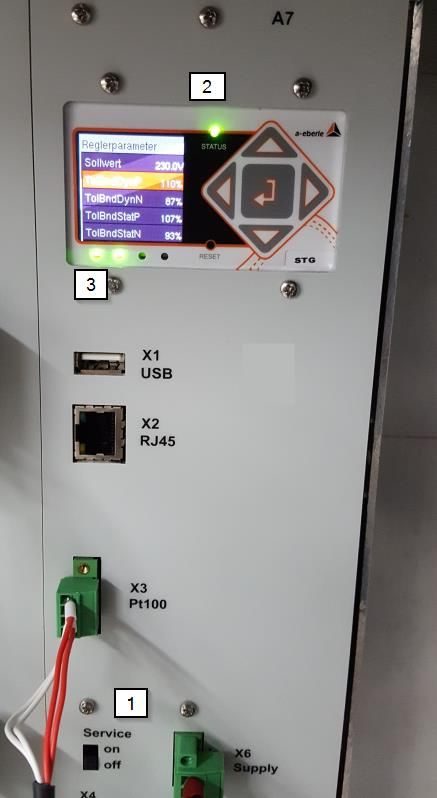
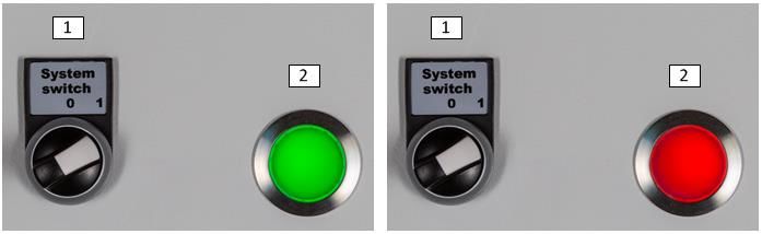
We take care of it.

8. Operation/Operation regulator
8.1 Indicator lamps/System switches

 Figure 8-1: Description system switch lamps control cabinet
 1) System switch
 2) Indicator lamp Operation (green) / error (red)

8.2 Indicator lamps & switch service – CPU board (A7)

 Figure 8-2: Slide switch service / lamp status
 Description:
 1) Service switch
 2) Status lamp
 3) Contactor status lamp (first from left) and service switch status lamp (second from left)

Page 14
8.3 Indicator lamps – Control cabinet The indicator lamps red and green indicate the status of the system: 0 Red: Error state; system is in automatic BYPASS. 0 Green: Operating state; system is in faultless operation. If the indicator lamp is red, follow the instructions in the service manual. Note down the error code (See chapter 8.12.5). If the error cannot be resolved, A. Eberle support team must be contacted. 8.4 Switches The switch positions lead to the following states: 0 System switch: 0 Figure 8-3: System switch (system on) – Switch position right: System on – Switch position top: System off 0 Service switch: Figure 8-4: service switch – Switch position on: Service switch active – Switch position off: Service switch inactive Service switch in position on indicator lamp changes from green to red. When the switch is in the on position, the service switch status lamp and the sta- tus lamp on the CPU board (A7) changes to red. Automatic BYPASS active, regulator is not in operation. Page 15
We take care of it. The service switch is only used for the firmware update process. 8.5 Boot process Activate the switch System switch (1) automatically starts the boot process of the regulator. After approx. 25 seconds, the display shows Boot.... After the boot process is completed (approx. 45 seconds), the regulator is now in automatic mode. The boot process must be completed in order to carry out all activities such as setting the LVRSys up, changing the display pages, etc. 8.6 Menu navigation In normal operation, the regulator is in automatic mode by default. The main window shows the 3 phase voltages of the phase conductors and the current stage of the respective phase. 2 1 3 6 4 5 Figure 8-5 Regulator display 1 Mode 2 Browse up (only in the user menu or active manual mode) 3 Enter key (confirm) 4 Browse right 5 Browse down (only in the user menu or active manual mode) 6 Browse left Table 8-1 Explanation of numbering Page 16
8.7 Automatic mode After the boot process (applying the supply voltage) is completed, the controller switches to Automatic mode. In Automatic mode, the controller is active. Figure 8-6 Display Automatic mode The display shows: 0 three phase voltages 0 current step positions of the phases 8.8 Manual mode The regulator is not active in Manual mode. One-step change per second is possible. Change steps manually: To select Manual mode, press the Enter key in Automatic mode. (See chapter8.9 Over- view display). To switch to a lower tap, press the down key. To switch to a high tap, press the up key. Figure 8-7 Manual mode display Page 17
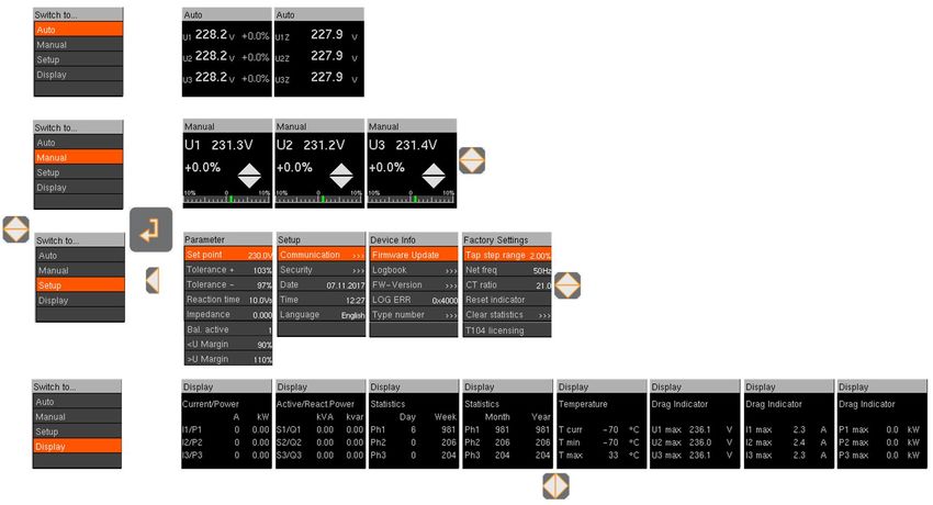
We take care of it.

8.9 Overview display

 Figure 8-8 Overview of menu navigation

Page 18
8.10 Parameters The individual controller parameters are described in detail below. Figure 8-9 Setting the regulator parameters Select the Parameter menu (See Section 8.9 Overview display). To select sub items, press the up or down key. Press the Enter key. Configuration: PIN input by pressing the up/down and left/right keys. Press Enter to confirm the PIN. Set the parameters by pressing the up/down and left/right keys. Press Enter to confirm the selection. On delivery the PIN is set to 0000 (four times zero) NOTE: The PIN can be changed as described in section 10 IT-Security. Page 19
We take care of it. Set point The default is: 0 230 V (400 V phase - phase) or 0 133 V (230 V phase - phase) Set the set point (100 V – 260 V). Tolerance band + and tolerance band - The defaults are: 0 97% for tolerance band – (Tolerance -) 0 103% for tolerance band + (Tolerance +) Set the tolerance bands if necessary (80 % - 98 % & 102% - 120 %). Figure 8-10 Tolerance band zone 1 Regulator active 2 Phasing process 3 Regulator inactive 4 Set point 5 Tolerance band + 6 Tolerance band - Table 8-2 Explanation of numbering If the voltage is in the range between the tolerance bands + and -, the control is inactive. If the tolerance bands + and – are exceeded, the control becomes active and steps the volt- age back to being inside the tolerance according to the parameters set. Page 20
Reaction time The default is 10 Vs. Reaction time adjustable from 1 Vs to 100 Vs in 0.1 steps Reaction time adjustable from 0 Vs to 100 Vs in 0.1 steps (FW 12.01.00) NOTICE! Reaction time 0 Vs is the high speed option < 30 ms feature (E2 – E5). This option is only possible in combination with specially designed transformers Selection of Reaction Time 0 Vs without special transformers can dam- age the system. The reaction time can be used to set up the control speed of the system. Example: Injury of tolerance bands with response time set to 1 Vs. (see Figure 8-11 Tolerance band zone) Tolerance band + exceeded by 1 V -> Stepping process after 1 s (2.1) Tolerance band – underrun by 0.5 V -> Stepping process after 2 s (2.2) The reaction time describes the time that elapses between the moments the tolerance band violation is detected until the step process occurs (see Sec. 8.10.2). Figure 8-11 Tolerance band zone reaction time 1 Regulator active 2.1 Phasing process exceed tolerance band + by 1 V 2.2 Phasing process underrun tolerance band - by 0.5 V 3 Regulator inactive 4 Set point 5 Tolerance band + 6 Tolerance band - Table 8-3 Explanation of numbering Page 21
We take care of it. Impedance The Impedance function can only be used if the Current measurement option has been inte- grated (Sec.Fehler! Verweisquelle konnte nicht gefunden werden.). The default impedance is 0 Ω: Impedance is inactive. Impedance adjustable in 0.01 Ω steps from zero to 0.5 Ω. Max. Influence on local voltage measurement 5 V (20 V with FW 12.01.00). When the impedance is inactive: Current-dependent regulation is inactive. When the impedance is active: Current values are included in regulation. Resistance symbol appears in the status window. Figure 8-12 Display impedance active When the impedance is selected, the load current is included in the regulation algorithm. Example: PV Feeder DT LVRSys™ 0.4kV 500 m KV Figure 8-13 Example grid branch with 500 m cable section Cable data Values Cable NA2X2Y 4 x 150 mm² Cable length 250 Cable resistance 0,25 km x 0,206 Ω/km = 0,05 Ω Table 8-4 Cable data Page 22
In the example, the calculated voltage value of the regulator is reduced by -100 A x 0.05 Ω = -5 V for a feeding current of the PV system of 100 A. As a result, the desired voltage set point is regulated at the end of the cable. When the impedance is selected, the regulator permanently calculates the voltage from the voltage value at the controller + impedance x grid current.. = + ∗ Type of wire spec. cable resistance Ω/km NAYY-J 4 x 70 mm² 0.453 NAYY-J 4 x 95 mm² 0.321 NAYY-J 4 x 120 mm² 0.255 NAYY-J 4 x 150 mm² 0.208 NAYY-J 4 x 185 mm² 0.167 NAYY-J 4 x 240 mm² 0.131 Overhead line AL 4 x 50 mm² 0.662 Overhead line AL 4 x 70 mm² 0.519 Overhead line AL 4 x 95 mm² 0.432 Table 8-5: Specific cable resistance Balancing (Bal. active) – from FW 12.00.05 The default is 1 (active). Set balancing 1 (active) or 0 (inactive). Function for balancing the three phase voltages within tolerance band +/-. 0 Balancing by steps toward set point. 0 Regulation ensure the optimum balance between the three phases depending to the step width. 0 Regulation within the tolerance band. 0 Activated impedance function is taken into account during balancing. Page 23
We take care of it.

 Example of unbalanced phase voltages:

 Figure 8-14 Example of unbalanced phase voltages

 Overvoltage warning – from FW 12.00.06
 The default is 110 % (related to set point). Adjustable from 105% to 150%.
 Overvoltage warning is active when the 10 seconds mean value of the voltage is above the
 set threshold.
 The overvoltage warning is transmitted via communication protocols and stored in the log-
 book under Event data.

 Undervoltage warning – from FW 12.00.06
 The default is 90 % (related to set point). Adjustable from 0% to 95%.
 Undervoltage warning is active when the 10 seconds mean value of the voltage is below the
 set threshold.
 The undervoltage warning is transmitted via communication protocols and stored in the
 logbook under Event data.

Page 24
8.11 Setup Figure 8-15 Setup Display Select the Setup menu (See Section 8.9 Overview display) To select the submenu items, press the up or down key. Press the Enter key. Configuration: PIN input by pressing the up/down and left/right keys. Press Enter to confirm the PIN. Set the parameters by pressing the up/down and left/right keys. Press Enter to confirm the selection. Communication See section 9 Communication. Security See section 10 IT-Security. Date Set the date. Time Set the Time. If NTP time synchronisation is activated (see section Fehler! Verweisquelle konnte n icht gefunden werden.) the date and time will be updated automatically. Language Possible languages: 0 German 0 English Page 25
We take care of it. 8.12 Device Info Figure 8-16 Device info display Select the Device info menu (see section 8.9 Overview display). To select the submenu items, press the up or down key. Press the Enter key. Configuration: Set up the PIN number by pressing the up/down and left/right keys. Press Enter to confirm the PIN. Set the parameters by pressing the up/down and left/right keys. Press Enter to confirm the selection. USB USB interface is used for firmware update and logbook backup. Figure 8-17 USB interface Firmware update CAUTION! Destruction of components due to overload! Start the update only when the service switch is activated. Activating the service switch isolates the thyristors from the mains voltage and bridges out the transformers. The control function is no longer in operation. A secure update process can be started. Copying the update files to a USB stick: Extract the zip file (from email or download: https://www.a-eberle.de/de/download-center-categories/firmware-1). Save the files on a FAT32 formatted USB stick Page 26
The folder structure below is mandatory, no parent folders on the USB stick (USB stick:\unpacked files; e.g. E:\...). Figure 8-18 Folder structure of the update on USB stick Complete update procedure: Activate the service switch to on (see section. 8.2). Regulator changes to error state. Insert the USB stick. Select the menu item Firmware update. Enter the PIN number by pressing the up/down and left/right keys. Press Enter to confirm the PIN. Press Yes to confirm the selection. Please wait appears in the display. Do not press any buttons or activate the service switch during the update process. Regulator needs about 5 minutes until the update process is completed. The regulator reinitializes itself. When the update is completed, the regulator remains in error state. Deactivate the service switch to off. Remove the USB stick. The regulator changes to automatic mode. The update procedure is finished. Logbook The logbook contains following items: Event data Event data list contains: 0 Parameters 0 New settings 0 State (Automatic/Manual) Page 27
We take care of it.

 0 Change of state (Automatic-Manual)
 0 Over- / Undervoltage warnings
 0 Error.

 Measurement data
 Measurement data list contains:
 0 U1 to U3 (10 minutes average values in V)
 0 U1Z to U3Z (10 minutes average values in V, only with option Current transformer and
 Impedance is set)
 0 I1 to I3 (10 minutes average values in A; only with option Current transformer)
 0 P1 to P3 (10 minutes average values in kW; only with option Current transformer)
 0 Q1 to Q3 (10 minutes average values in kvar; only with option Current transformer)
 0 S1 to S3 (10 minutes average values in kVA; only with option Current transformer)
 0 T1 to T3 (10 minutes average values in °C)
 0 Tap 1 to Tap 3 (current tap position Ph1-Ph3 at the time)
 0 Taps/Period 1-3 (number of steps within 10 minutes Ph1-Ph3).

 Service data
 Service data is intended exclusively for the A. Eberle GmbH & Co. KG. support team.

Page 28
Figure 8-19 Overview read logbook 8.12.3.1 Download Logbook via USB stick To download the logbook via USB stick you have to be in front of the LVRSys and follow these steps. Insert the USB stick. Select menu item Logbook. Select submenu item Start time. Data beginning from the start time up to now is saved. The data Event data, measurement data, service data must be selected for storage. 0 ( ) Selection inactive 0 (x) Selection active Select the submenu item Event data, measurement data and service data. Select with the up or down key. Enter the PIN number by pressing the up/down and left/right keys. Page 29
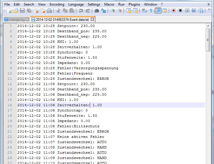
We take care of it. Press Enter to confirm the PIN. Press Yes to confirm the selection. Select the submenu item Archive data. Press Yes to confirm the selection. Please wait appears in the display. Regulator stores data on the USB stick. 8.12.3.2 Download via LVRSysUpdater See chapter Fehler! Verweisquelle konnte nicht gefunden werden. Fehler! Verweisquelle ko nnte nicht gefunden werden.. 8.12.3.3 Evaluating the logbook (measurement data) with Microsoft Excel (alternative spreadsheet programs can also be used). A. Eberle provides an Excel macro and a descriptive video on the homepage. https://www.a-eberle.de/en/downloads/low-voltage-regulation/analysis-support Evaluation without macro Open the Measurement data in Excel. 8.12.3.4 Evaluating the logbook (Event data) in Notepad++ (alternative text editing programs can also be used). Page 30
Figure 8-20 Event data opened with Notepad++

 Page 31
We take care of it. 8.12.3.5 Evaluating the logbook (Event data) in WinPQ mobil For Evaluation of Event data with WinPQ mobil you have to follow these steps: Installation of software WinPQ mobil. https://www.a-eberle.de/de/download-center-categories/f%C3%BCr-mobile- analysatoren Download of Event data in .csv-format (See Section 8.12.3.1 or 8.12.3.2). Start of Program LVRSys WinPQ mobil. Contact the support team of A. Eberle GmbH & Co. KG. Open of Event data in .csv-format. Choose control range LVRSys with dropdown menu (6 – 24 %). Confirm the control range with OK. WinPQ mobil opens a window Evaluation period for the period of Evaluation. Choose the period of Evaluation, confirm with OK. Event data Evaluation in WinPQ mobil Figure 8-21 Event data opened with WinPQ mobil Page 32
Table of data points
 WinPQ-mobil LVRSys
 UL1 U1_V
 UL2 U2_V
 UL3 U3_V
 Ueff
 U12 U1_V_Input
 U23 U2_V_Input
 U31 U2_V_Input
 IL1 I1_A
 Ieff IL2 I2_A
 IL3 I3_A
 P L1 P1_kW
 P L2 P2_kW
 Real power
 P L3 P3_kW
 P total P_total
 Q L1 Q1_kvar
 Q L2 Q2_kvar
 Reactive power
 Q L3 Q3_kvar
 Q total Q_total
 S L1 S1_kVA
 S L2 S2_kVA
 Apparent power
 S L3 S3_kVA
 S total S_total
 PHL1 Phase angle_Phi1
 Phase angle u1E -i1 PHL2 Phase angle_Phi2
 PHL3 Phase angle_Phi3
 PF L1 Tap_Ph1_%
 Power factor PF L2 Tap_Ph2_%
 PF L3 Tap_Ph3_%
 QFL1 Taps_per_period_Ph1
 Reactive factor QFL2 Taps_per_period_Ph2
 QFL3 Taps_per_period_Ph3
 Voltage/THD THDNE T_°C
 UL1 max UZ1_V
 Ueff max (10ms) UL2 max UZ2_V
 UL3 max UZ3_V
Table 8-6 Referencing data points between measurement data LVRSys and WinPQ-mobil

 Page 33
We take care of it. Firmware-Version Menu item FW-Version contains information about: 0 Firmware - version 0 Cortex-firmware - version 0 Kernel - version 0 File system - version The version number is determined automatically. No changes possible. LOG ERR Display of the last occurred error. If the system malfunctions, note the fault. Contact the support team of A. Eberle GmbH & Co. KG. Error Error code Contactor 0x00001 Overvoltage 0x00002 Under voltage 0x00004 Internal regulation error 0x00008 0x00010 0x00020 0x00040 0x00080 0x00100 0x00400 0x01000 EEPROM 0x00020 Service switch 0x00200 Invalid serial number 0x00800 Thyristor board A1 0x02000 A2 0x04000 A3 0x08000 A4 0x10000 A5 0x20000 A6 0x40000 Transformer temperature 0x80000 Table 8-7 Error code table Page 34
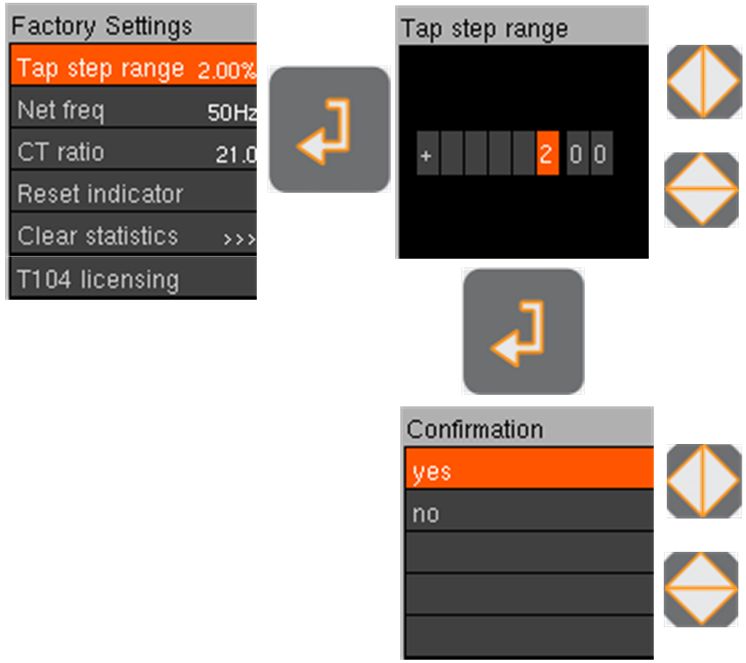
The individual error codes add up as follows: Error Error code Internal regulation error 0x01000 Service switch 0x00200 Internal regulation error 0x00080 Under voltage 0x00004 LOG ERR 0x1284 Table 8-8 Menu tab LOG ERR The zeros after the x are not displayed. Type number Menu item Type number contains information about: 0 Device number 0 Type number CPU board 0 Type number Thyristor boards The device number is set at the factory. Do not change the device number. The type number of CPU board and thyristors boards are determined automatically by the system. No changes possible. 8.13 Factory settings CAUTION! Malfunction of the regulator due to incorrect settings ! Do not change factory settings. The factory settings are only set when the system is set up for the first time and are directly coordinated with the installed hardware. These must not be changed by the user. Page 35
We take care of it. Figure 8-22 Setting the factory parameters Select the Setup menu (See Section 8.9 Overview display). To select the item submenu, press the up or down key. Press the Enter key. Configuration: Enter the PIN number by pressing the up/down and left/right keys. Press Enter to confirm the PIN. Set the parameters by pressing the up/down and left/right keys. Press Enter to confirm the selection. Step width The step width is set at the factory. Do not change the step width. Network frequency The frequency is set at the factory Do not change the network frequency. CT ratio (current transformer ratio) Using current transformers from A. Eberle GmbH & Co. KG. the transfer ratio is set at the factory. When using external current transformer: Enter the conversion ratio. Resetting the indicator The Indicator or Drag indicator sets 15 min average values for the: Page 36
0 Maximum voltages (Phase 1-3) 0 Maximum currents (Phase 1-3) 0 Maximum power values (Phase 1-3) 0 Maximum and minimum temperature in the switch cabinet in °C (T). Reset indicator: Select Reset indicator. Enter the PIN number by pressing the up/down and left/right keys. Press Enter to confirm the PIN. Confirm selection. All indicators are reset to their initial state. Clear statistics The statistics can be cleared as required: 0 Everything 0 Day 0 Week 0 Month 0 Year. Clear individual statistical values: Select. PIN input by pressing the up/down and left/right keys. Press Enter to confirm the PIN. Confirm selection. Selected statistical value is cleared. Page 37
We take care of it.

9. Communication
9.1 Ethernet
 Ethernet interface serves as communication interface for Modbus and IEC 60870-5-104 ap-
 plications.
 Ethernet interface has been deactivated for this model. (shown on the label)

 Figure9-23 Ethernet interface (deactivated)

Page 38
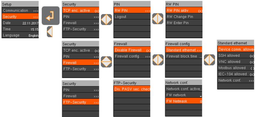
10. IT-Security Figure 10-1 Overview security parameters Selection of the sub item security for setting security-relevant parameters. 0 Change and adjust the PIN. 0 Shut down and allow protocols. 0 Shut down and allow remote access. 0 Encrypt TCP/IP packets. 0 Shut down and activate Ethernet interface. Page 39
We take care of it. 11. External devices & modifications An installation space of WxDxH 400x100x300 mm in the controller cabinet is available for external devices. Larger installation space is possible after consultation with A. Eberle. 11.1 External devices External devices will be installed and wired by A. Eberle GmbH & Co. KG by arrangement. External devices are e. g.: 0 Communication Modems 0 Remote control systems 12. Servicing/Cleaning/Spare parts 0 The service interval depends on the operating and environmental conditions. 0 The service interval can be determined by the customer himself. An interval of 5 years is recommended. 0 For service purposes A. Eberle provides a separate service manual. Please contact the A. Eberle support team for a copy 13. Standards and Laws (all based on European standards) Low voltage directive 2014/35/EU DIN EN 61439-1 Low-voltage switchgear and control gear assemblies - Part 1: General rules DIN EN 61439-5 Low-voltage switchgear and control gear assemblies - Part 5: Assem- blies for power distribution in public networks DIN EN 0298-4 Application of cables and cords in power installations - Part 4: Recom- mended current-carrying capacity for sheathed and non-sheathed cables for fixed wirings in buildings and for flexible cables and cords DIN EN 61000-6-1 Electromagnetic compatibility (EMC) - Part 6-1: Generic standards - Immunity for residential, commercial and light-industrial environments DIN EN 61000-6-3 Electromagnetic compatibility (EMC) - Part 6-3: Generic standards - Emission standard for residential, commercial and light-industrial environments DIN EN 50160 Voltage characteristics of electricity supplied by public distribution net- works DIN EN 82079-1 Preparation of instructions for use - Structuring, content and presenta- tion - Part 1: General principles and detailed requirements Page 40
14. Disassembly & disposal DANGER! Danger of electric shock! Only disassemble the LVRSys™ when it is de-energised Make sure the LVRSys™ is completely de-energised. Remove low voltage cables. Remove local cabinet grounding. The disposal of the LVRSys™ is carried out by A. Eberle GmbH & Co. KG. Send all components to: A. Eberle GmbH & Co. KG Frankenstraße 160 D-90461 Nuremberg 15. Warranty A. Eberle GmbH & Co. KG. warrants that this product and accessories will be free from de- fects in materials and workmanship for a period of three years from the date of purchase. Warranty does not apply to damage caused by: 0 Accidents 0 Misuse 0 Abnormal operating conditions To make a warranty claim, please contact your local A. Eberle distributor or alternatively contact A. Eberle GmbH & Co KG in Nuremberg, Germany. Page 41
We take care of it.

Notes

 Notes
Page 42
A. Eberle GmbH & Co. KG

Frankenstraße 160
D-90461 Nuremberg

Tel.: +49 (0) 911/62 81 08-0
Fax: +49 (0) 911/62 81 08 96
Email: info@a-eberle.de
http://www.a-eberle.de

Edition of: 15/05/2020
Version: 180.1000.2xxx_BA LVRSys_HGÜ_en_V_1_10
Copyright 2013 - 2021 A. Eberle GmbH & Co. KG

Subject to change without prior notice.
You can also read