Operating Manual Network Analyzer PQ-Box 150 - A. EBERLE
←
→
Page content transcription
If your browser does not render page correctly, please read the page content below
Operating Manual
                                 Network Analyzer
                                   PQ-Box 150

    Available user manuals:
    0 Operating manual PQ-Box 150 Hardware (this print version)
    0 Operating manual WinPQ mobil Software (available as PDF download from our homepage
       via www.a-eberle.de/en/downloads/power-quality/user-manuals/ or via
       WinPQ mobil software --> Help)

g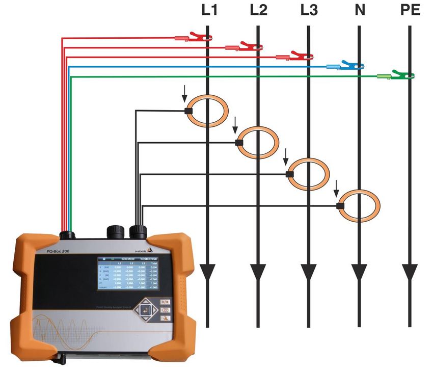
We take care of it

              Note:
              Please note that this operating manual cannot describe the latest version of the device in
              all cases. For example, if you download a more recent firmware version from the internet,
              the following description may no longer be accurate in every point.
              In this case, either contact us directly or refer to the most recent version of the operating
              manual, available on our website (www.a-eberle.de).

              A. Eberle GmbH & Co. KG
              Frankenstraße 160
              D-90461 Nuernberg
              Tel.: 0911 / 62 81 08 0
              Fax: 0911 / 62 81 08 96
              E-Mail:     info@a-eberle.de
              Internet:   www.a-eberle.de

              A.-Eberle GmbH & Co. KG cannot be held liable for any damage or losses, resulting from
              printing errors or changes to this operating manual.

              Furthermore, A. Eberle GmbH & Co. KG does not assume responsibility for any damage or
              losses resulting from defective devices or from devices altered by the user.

              Copyright 2017 by A. Eberle GmbH & Co. KG
              All rights reserved.

2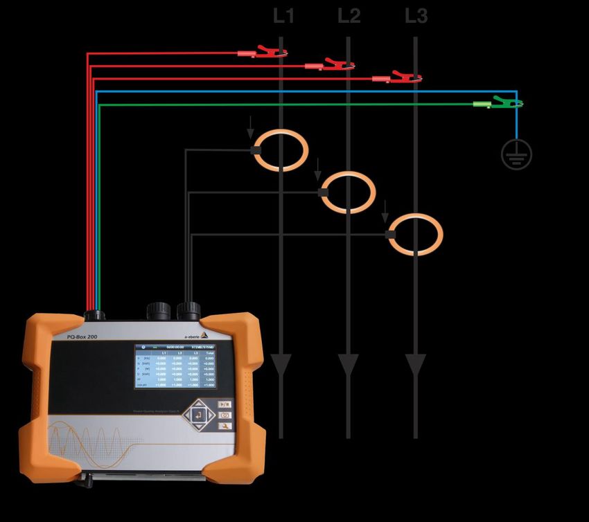
Table of Contents
1.       User Guidance................................................................................................................ 5
1.1      Target group..............................................................................................................................5
1.2      Warnings ...................................................................................................................................5
1.3      Tips ............................................................................................................................................5
1.4      Other Symbols...........................................................................................................................6
1.5      Applicable documentation ........................................................................................................6
1.6      Keeping .....................................................................................................................................6
1.7      Updated documentation...........................................................................................................6
2.       Safety Instructions ......................................................................................................... 7
2.1      Safety instructions ....................................................................................................................7
2.2      Meaning of the symbols used on the device ............................................................................8
3.       Scope of Delivery/Order Codes PQ-Box 150 .................................................................... 9
3.1      Scope of Delivery ......................................................................................................................9
3.2      Order Codes ..............................................................................................................................9
3.3      Technical data PQ-Box 150 .................................................................................................... 11
4.       External power supply ...................................................................................................13
4.1      Requirement external power supply ..................................................................................... 13
4.2      External power supply ........................................................................................................... 13
5.       Accessories for current measurement ............................................................................15
5.1.1    Rogowski current clamps ....................................................................................................... 15
5.1.2    Current clamps ....................................................................................................................... 16
5.1.3    Accessories for current measurement ................................................................................... 17
6.       Intended use .................................................................................................................18
7.       Description ...................................................................................................................18
8.       Hardware PQ-Box 150 ...................................................................................................19
8.1      PQ-Box 150 Hardware............................................................................................................ 19
8.1.1    Overview PQ-Box 150 ............................................................................................................ 19
9.       Battery management and micro SD card ........................................................................22
9.1      Micro SD card ........................................................................................................................ 22
9.2      Accumulator ........................................................................................................................... 22
10.      Network connection PQ-Box 150 ...................................................................................23
10.1.1   Direct connection to a 3-phase low voltage network ............................................................ 23
10.1.2   Connection to a single-phase low voltage network............................................................... 24
10.1.3   Connection to an isolated network........................................................................................ 25
10.1.4   Connection to secondary transformer ................................................................................... 26

                                                                                                                                                         3
We take care of it

11.           Display ..........................................................................................................................28
11.1          Starting a measurement ........................................................................................................ 31
11.2          Manual Trigger ....................................................................................................................... 31
11.3          Time synchronisation using the RS232 interface ................................................................... 32
11.4          PQ-Box 150 Setup .................................................................................................................. 32
11.5          Keypad Lock ........................................................................................................................... 35
11.6          Password Protection and Interface Lock ............................................................................... 35
11.7          Memory management ........................................................................................................... 36
11.8          Delete device memory ........................................................................................................... 37
11.9          Continuous mode without power supply .............................................................................. 37
11.10         TCP-IP settings........................................................................................................................ 38
11.11         WLAN Settings (Option for PQ-Box 150)................................................................................ 39
12.           PQ-Box App ..................................................................................................................40
12.1          Connection to PQ-Box ............................................................................................................ 40
13.           Maintenance/Cleaning ..................................................................................................41
14.           Calibration ....................................................................................................................41
15.           Disposal ........................................................................................................................41
16.           Product Warranty .........................................................................................................42

4
1.         User Guidance

     1.1   Target group
           The User Manual is intended for skilled technicians as well trained and certified operators.
           The contents of this User Manual must be accessible to people tasked with the installation
           and operation of the system.

     1.2   Warnings
           Structure of the warnings
           Warnings are structured as follows:
                SIGNAL             Nature and source of the danger.
                WORD
                                   Consequences of non-compliance.
                                       0 Actions to avoid the danger.

           Types of warnings
           Warnings are distinguished by the type of danger they are warning against:
                DANGER!          Warns of imminent danger that can result in death or serious injuries
                                 if not avoided.

                WARNING!         Warns of a potentially dangerous situation that can result in death or
                                 serious injuries when not avoided.

                CAUTION!         Warns of a potentially dangerous situation that can result in
                                 fairly serious or minor injuries when not avoided.

                NOTICE:          Warns of a potentially dangerous situation that if not avoided
                                 could result in material or environmental damage.

     1.3   Tips
                    Tips on the appropriate device use and recommendations.

                                                                                                          5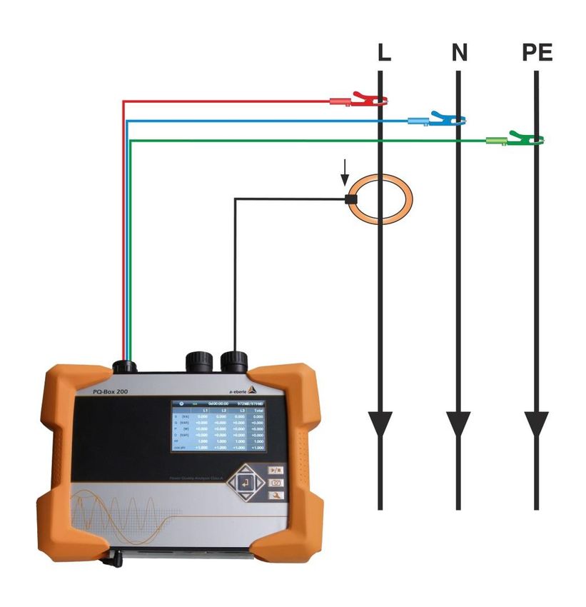
We take care of it
1.4 Other Symbols
Instructions
Structure of instructions:
Guidance for an action.
→ Indication of an outcome, if necessary.
Lists
Structure of unnumbered lists:
0 List level 1
– List level 2
Structure of numbered lists:
1) List level 1
2) List level 1
1. List level 2
2. List level 2
1.5 Applicable documentation
For the safe and correct use of the product, observe the additional documentation that is
delivered with the system as well as the relevant standards and laws.
1.6 Keeping
Keep the user manual, including the supplied documentation, readily accessible near the
system.
1.7 Updated documentation
The most recent versions of the documents can be obtained at https://www.a-
eberle.de/de/downloads.
6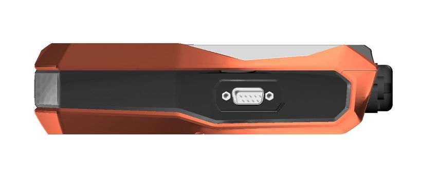
2. Safety Instructions
2.1 Safety instructions
Follow the operating instructions.
Keep the operating instructions with the device.
Ensure that the device is operated only in a perfect condition.
Never open the device.
When opening the battery compartment, disconnect the power supply.
Ensure that only qualified personnel operate the device.
Connect the device only as specified.
Ensure that the device is operated only in the original condition.
Connect the device only with recommended accessories.
Ensure that the device is not operated outside the design limits. (See the technical data)
Ensure that the original accessories are not operated outside the design limits.
For measurements in short circuit resistant systems, ensure that voltage taps with integrated fuses
are used.
Do not use the device in environments where explosive gases, dust or fumes occur.
Clean the device only with commercially available cleaning agents.
DANGER! Danger to life due to electric shock!
If the device is used in a way not specified by the equip-
ment producer, the device protection will be impaired.
Observe safety instructions
7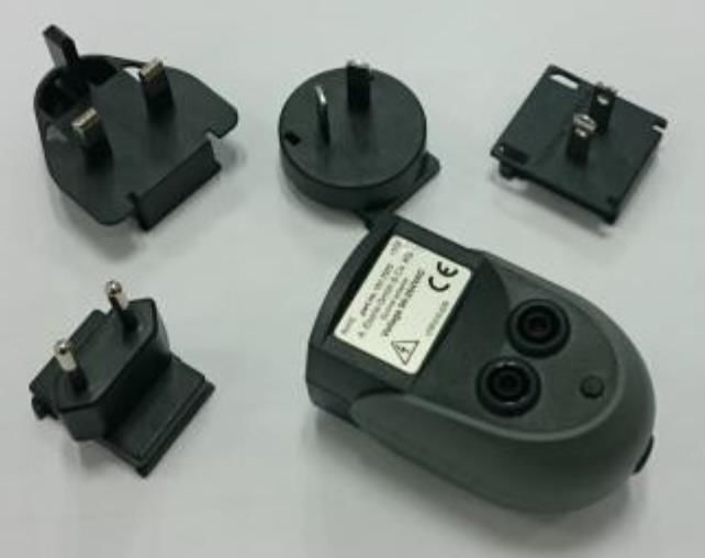
We take care of it

    2.2       Meaning of the symbols used on the device

                  Nature and source of the danger! Read the safety instructions inside the manual!

                  Voltage ground

                  USB-interface

                  TCP-IP interface

                  CE marking guarantees compliance with the European directives and regulations regarding EMC

                  The unit is fully protected by double or reinforced insulation.

                  6X = Protection against dust
       IP65       Protection against water X5 = Protection against water jets from any angle

                  AC voltage

                  DC voltage

                  Maximum allowed RMS voltage against earth potential

    CAT IV        Category IV

8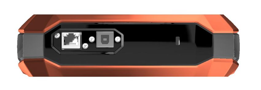
3.             Scope of Delivery/Order Codes PQ-Box 150

     3.1       Scope of Delivery
     0     PQ-Box 150
     0     User Manual
     0     Case
     0     3 red dolphin clips, 1 blue dolphin clip, 1 green dolphin clip
     0     3 high-load fuses integrated in voltage leads
     0     USB cable, Ethernet cable
     0     AC socket adapter with country-specific adapters
     0     Wide range power supply with 2 x 4 mm safety plugs and integrated high-load fuses
     0     2 pcs. 4mm safety connectors (to staple power supply and voltage leads to one dolphin clip)

     3.2       Order Codes
The following device options are available for the PQ-Box 150 device and can be activated at any time
via a license code.
           1 Optional “WLAN-Wifi” (S1)
-WLAN-Wifi interface for wireless communication with PQ-Box 150.

                  With a licence code, the PQ-Box 150 can be upgraded with option S1

           1 Optional “Ripple control recorder” (R1)
- Used for triggering and recording ripple control signals for voltages and currents.

                  With a licence code, the PQ-Box 150 can be upgraded with ripple control recorder.

                                                                                                         9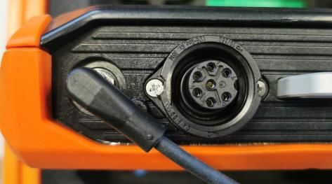
We take care of it

        Network Analyzer                                                                               PQ-Box 150
        Option                                                                               Basic   Basic+     Light     Expert
        Measurement functions
        Voltage: ½ periode min. max. average                                                   x        x         x             x
        Current: ½ periode min. max. average                                                   x        x         x             x
        Power: P, Q, S, PF, cos phi, sin phi, tan phi                                          x        x         x             x
        Distortion-, fundamental reactive-, modulation- and unbalance power                    x        x         x             x
        Energie: P, Q, P+, P-, Q+, Q-                                                          x        x         x             x
        Flicker (Pst, Plt, Pinst)                                                                       x         x             x
        Unbalanced voltage, current; positive sequence/ negative sequence/                              x         x             x
        Voltage harmonics according IEC 61000-4-30 Ed. 3 Class A - bis 50.                              x         x             x
        Voltage harmonics extreme values 2. bis 50. (200ms RMS)                                         -         x             x
        Phase angle of voltage harmonics                                                                -         x             x
        Voltage harmonics 200Hz frequency bands - 2 kHz bis 9 kHz                                       -         -             x
        Supraharmonics 2 kHz to 170 kHz (200Hz / 2kHz frequency bands)                                  x         x             x
        Current harmonics 2. bis 50.                                                                    -         x             x
        Current harmonics extreme values 2. to 50. (200ms RMS)                                          -         -             x
        Current harmonics 200 Hz Frequenzbänder 2 kHz bis 9 kHz                                         -         x             x
        Phase angle of current harmonics according fundamental of voltage                               -         x             x
        P, Q, S, cos phi of harmonics                                                          x        x         x             x
        THD U and I ; PWHD U and I ; PHC                                                       -        -               10kHz
        Frequency spectrum with 5Hz resolution up to:                                                             x             x
        Ripple control signal 100 Hz to 5 kHz (200ms RMS max value)                            x        x         x             x
        10/15/30 min interval P, Q, S, D, cos phi, sin phi (additional to other intervals)     x        x         x             x

        Online mode
        Oscilloscope recorder - sampling frequency                                                          20,46kHz
        Power triangle 3D of active-, reactive, apparent power and distortion                  x        x         x             x
        Voltage harmonics and current harmonics                                                         x         x             x
        Interharmonic groups (U, I)                                                                     x         x             x
        Voltage harmonics and current harmonics
                                                                                                        -         -             x
        200 Hz frequency band - 2 kHz bis 9 kHz
        Supraharmonics up to 170kHz (200Hz or 2kHz frequency band)                                      -         x             x
        Triggerfunctions (Oscilloscope & ½ Periode RMS recorder)
        Manual trigger via button                                                              -        x         x             x
        RMS level trigger (U, I)                                                               -        x         x             x
        RMS jump trigger (U, I)                                                                -        x         x             x
        ½ periode frequency trigger (level; df/dt)                                             -        -         x             x
        Phase shift trigger                                                                    -        -         x             x
        Envelope trigger                                                                       -        -         x             x
        Interval-trigger                                                                       -        -         x             x
        Automatic-trigger                                                                      -        -         x             x

               With a licence code, the PQ-Box 150 can be upgraded from lower version to a higher version.

10
3.3 Technical data PQ-Box 150
4 voltage inputs (TRMS): L1, L2, L3, N, PE
Maximum input voltage: 565V AC/800V DC L-N
980V AC/1380V DC L-L
Input Impedance: 10 MΩ impedance
4 current inputs (AC/DC): 1000 mV-input for Rogowski
330mV for current clamps
Impedance: 10 kΩ
Sampling frequency: 20,48 kHz
Synchronisation fundamental frequency: 45 Hz bis 65 Hz
Measurement intervall: Free from 1 sec to 30 min
Memory 4 GByte standard
Mikro-SD card (industrie standard): Optional bis 32 GByte
Interface: USB 2.0
TCP/IP 100Mbit
Time synchronisation: DCF77 or GPS clock (RS232)
Abmessungen: 202 x 181 x 40 mm
Weight: 1,0 kg
IP protection: IP 65
IEC 61000-4-30 (Ed. 3): Klasse A
Accuracy voltage and current input: < 0,1%
Category: CAT IV / 600V
Overvoltage Pulse voltage = 12,8 kV
5 sec = 7,4 kV rms
A/D converter: 24 Bit
Temperature: Funktion: -20° ….60°C
Storage:-30°….80°C
TFT-display: 100 x 60 mm
Power supply: 15V / < 10VA
11We take care of it
Measurement quantity Error limits according IEC 61000-4-30, Class A
Fundamental oscillation: r.m.s. ±0.1% of Udin
over 10% ~ 150% of Udin
Fundamental oscillation: Phase ± 0.15°
over 50% ~ 150% of Udin
over fnom ±15%
2nd ... 50th harmonic ±5% of display over Um = 1% ~ 16% of Udin
±0.05% of Udin over Um < 1% of Udin
2nd .... 49th interharmonic ±5% of display over Um = 1% ~ 16% of Udin
±0.05% of Udin over Um < 1% of Udin
Frequency ± 5mHz over fnom ±15% (fnom = 50 Hz / 60 Hz)
Flicker, Pst, Plt ±5% of display over 0.02% ~ 20% of ∆U / U
Dip residual voltage ±0.2% of Udin over 10% ~ 100% of Udin
Dip duration ±20 ms over 10% ~ 100% of Udin
Swell residual voltage ±0.2% of Udin over 100% ~ 150% of Udin
Swell duration ±20 ms over 100% ~ 150% of Udin
Interruption duration ±20 ms over 1% ~ 100% of Udin
Voltage asymmetry ±0.15% over 1% ~ 5% of display
Ripple control voltage ±5% of display over Um = 3% ~ 15% of Udin
±0.15% of Udin over Um = 1% ~ 3% of Udin
124. External power supply
4.1 Requirement external power supply
Maximum power consumption incl. Backlight Output power supply:
PQ-Box 150 Voltage: 15V DC
Current: 0,58A
CAUTION! Device protection
In order not to reduce the device protection class and surge strength
of the network analyzer, the following requirements must be met by
the external power supply. If these details are reduced, so the entire
PQ-Box is reduced to this lower requirement.
IP protection IP 65
Temperature Function: -20° ….60°C
Storage: -30°….70°C
Overvoltage EN61010-1
category 600V / CAT IV
surge 12kV 1,2/50 ysec
AC voltage 7,4kV 5 sec
Polarity of the external voltage supply with 15V DC
4.2 External power supply
Scope of Delivery PQ-Box 150:
0 AC socket adapter with country-specific adapters (582.0509)
0 Wide range power supply with safety plugs and integrated high-load fuses (111.7069)
0 2 pcs. 4mm safety connectors (582.2037)
The PQ-Box 150 is equipped with an extremely robust power supply unit. The power supply is designed
for high noise immunity of 600V CAT IV and meets the IP65 protection class.
13We take care of it
The PQ-Box can be supplied with energy directly at the measurement place and does not require a sock-
et. The following voltage ranges for the power supply are possible: 100V to 440V AC or 100V to 300V
DC.
In fuse carrier only 6.3mm x 32mm, 3 A, F,
fuses are allowed, with a shut-off value of
50kA. Only fuses with the identical data must
be used.
Suggestion: SIBA, Part.no. 7009463; 3AF
With two short adapter cables, the user has the option to staple the wide range power supply and the
voltage leads the network analyzer to one dolphin clip.
Socket adapter with 4 mm safety banana plugs for voltage Measurement or connection of the wide
range power supply at a socket.
CAUTION! Damage to power supply due to under- or overvoltage
supply device only with 100-440 V AC voltage.
supply device only with 100-300 V DC voltage.
do not supply the device directly from highly disturbed voltages.
(for. example, a frequency inverter output / caution at high
transients or high sampling frequency)
145. Accessories for current measurement
- Standard accessories are automatically recognized by the meter.
- The conversion factor is automatically adjusted for the connected accessory.
5.1.1 Rogowski current clamps
1 Rogowski current clamp 4~: Ident-No. 111.7001
1 Rogowski current clamp 4~: Ident-No. 111.7006
Model 111.7001/6
Model 111.7001 Pro Flex 3000 4~ 111.7006 Pro Flex 6000 4~
Current range 3,000 A AC RMS 6,000 A AC RMS
Measurement range 0-3300 A AC RMS 0-6,600 A AC RMS
Output voltage 85 mV / 1000 A 42.5 mV / 1000 A
Frequency range 1 Hz to 20 kHz 10 Hz to 20 kHz
Isolation voltage type 600 V AC / DC CAT IV 600 V AC / DC CAT IV
AccuracyWe take care of it
Automatic current clamp factor detection.
In this example the PQ-Box set the clamp factor to 1
5.1.2 Current clamps
The MU-metal clamp is especially applicable for small current measurements on secondary transformers
in medium- and high-voltage networks. High accuracy and small angle errors are combined.
1 Mu-Metal Mini-Current clamps 3~: Ident-No. 111.7003
Current range: 10mA to 20A
Frequency range: 40Hz to 20kHz
1 Mu-Metal Mini-Current clamps 4~: Ident-No. 111.7015
Current range: 10mA to 20A/200A AC RMS (two ranges)
Frequency range: 40Hz to 20kHz
Model 111.7015
Measurement range 20 A measurement range 200A measurement range
Current range 20 A AC RMS 200 A AC RMS
Measurement range 100 mA to 20 A RMS 1 A to 200 A RMS
Output voltage 10 mV/A 1 mV/A
Frequency range 40 Hz to 20 kHz 40 Hz to 20 kHz
Isolation voltage type 600 V AC 600 V AC
Accuracy 100 mA- 10 A/1.5 % of the meas- 10-40 A/1 Mu-Metal Mini-Current clamp 0…5A 1~: Ident-No. 111.7043
Current range: 5mA to 5A AC RMS
Frequency range: 40Hz to 20kHz
Free current adapter set necessary
1 AC/DC Current clamp 1~: Ident-No. 111.7094
AC/DC hall sensor clamp. Set with power supply and 2 pcs. 4mm connectors
Current range 60A/600A (two ranges)
Model 111.7094
Measurement range AC/DC 60 A AC/DC 600 A
Current range 60 A DC / 40A AC RMS 600 A DC / 400A AC RMS
Measurement range 200 mA to 60 A RMS 600 A RMS
Output voltage 10 mV/A 1 mV/A
Frequency range DC to 10 kHz DC to 10 kHz
Isolation voltage type
Accuracy 0.5-40 A/We take care of it
CAUTION! Damage to the device from external current clamps
Do not use clamps with A or mA output
Avoid input voltages at the current inputs greater than 30 V
1 Current clamp cable extension: Ident-No.: 111.7025
Cable extension 5 m for current clamps or Rogowski coils.
1 Current-shunt 2A: Ident-No.: 111.7055
Measurement of AC- and DC-currents. Current range = 2A / 200mV output signal
6. Intended use
The product is exclusively for the measurement and evaluation of voltages and currents. The current
inputs are mV-inputs.
Observe safety instructions
Ensure that the device is not operated above the rated data
7. Description
The Network Analyzers PQ-Box 150 & 200 are suitable for analysis in low, medium and high-voltage
networks. They meet all the requirements of the measurement equipment standard IEC61000-4-30
Ed. 3 class A.
Functions:
→ Voltage quality measurements according to EN50160, IEC61000-2-2 and IEC61000-2-4 for
low and medium voltage networks
→ Fault recorder functions
→ Load analyses; energy measurements
→ Ripple control signal analysis
→ Transient analysis
188. Hardware PQ-Box 150
8.1 PQ-Box 150 Hardware
8.1.1 Overview PQ-Box 150
Top panel view
3 2 1
1) Securely connected voltage inputs
L1 (red + label L1)
L2 (red + label L2)
L3 (red + label L3)
N (blue + label N)
Measurement ground (green + label E)
DANGER! Danger to life due to electric shock!
The maximum voltage of the blade (green) must not exceed the re-
quirement of 600V against earth
Ensure that the device is not operated above the rated data
CAUTION! Damage to measurement voltage with overvoltage
Connect device to maximum DC voltage of 565V AC / 800V DC L-N.
Connect device to maximum AC voltage of 980V AC / 1380V DC L-L.
2) Current clamp connection (7-pin plug)
3) 15 V DC power supply
DC power supply angle 45 °
19We take care of it
Front panel - keypad
Measurement Start / Stop
Manual trigger
Setup
Panel with 5 keys for scrolling and
changing setup parameters
20Bottom view
2 3 1
1) Kensington lock
2) TCP/IP interface
3) USB 2.0 interface
Side view
1
1) RS232 interface – for connecting a DCF77 or GPS radio clock
Rear view
Under the cover you find a battery pack
and a card slot for a micro SD card (1 Gb to
32 Gb)
Open the screws with a torx (TX15) screw
driver.
21We take care of it
9. Battery management and micro SD card
9.1 Micro SD card
To replace the microSD card, please note the following:
- The PQ-Box 150 support microSD cards up to a maximum size of 32 GB.
- We recommend the use of an industrial micro-SD card, to reach the temperature range from
-20 ° C to +50 ° C of the PQ Box.
- Insert the micro SD card into the appropriate slot in the correct direction. The correct
direction is defined by a notch on the microSD card.
9.2 Accumulator
The PQ Box 150 are equipped with a lithium-ion battery and intelligent charging electronic.
The aim is to achieve a long battery life time. At 80% capacity, the PQ-Box can run approximately 6
hours without mains supply.
The Li-ion battery is first charged to 100% when the threshold (75%) is reached. This has a very positive
effect on the total life time of the batteries.
Aging: At high temperature and the battery is full, the cell oxidation developed particularly rapidly. This
condition may occur, f. e. in notebooks when the battery is fully charged and at the same time, the de-
vice is in operation. The optimal charge level is between 50% and 80% during storage.
– Charging stops when exceeding a battery temperature of 50 ° C
– Start charging only when the battery temperature is less than 45 ° C
– Warning Battery capacity below 7%
– PQ-Box shutdown when battery capacity = 100% --> four green bars
state of charge >= 75% --> three green bars
state of charge >= 40% --> two green bars
state of charge >= 20% --> one red bar
state of charge < 20% --> empty
We recommend storing the battery of the PQ-Box at 15 ° C with a charge of 60% - this is a
compromise between accelerated aging and self-discharge. The battery of the PQ-Box should
be recharged to approximately 55-75% every six months, due to the natural self-discharge, in
order to ensure a long-term service life.
2210. Network connection PQ-Box 150
10.1.1 Direct connection to a 3-phase low voltage network
Connection in a 3-phase 4-wire AC network
Voltage connection
Ensure that voltage measurement cable PE is connected for every measurement.
If no PE connection is available, connect E and N together.
Ensure that switching (4-wire) is selected. (Setting via display or software)
23We take care of it 10.1.2 Connection to a single-phase low voltage network Connection for single-phase measurements Voltage connection Ensure that voltage measurement cable E is connected for every measurement. If no PE connection is available, connect E and N together. Ensure that switching “1-wire system” is selected. (Setting via display or software) Not necessary to connect phases L2 and L3 for voltage and currents in single phase measurement. 24
10.1.3 Connection to an isolated network
Connections
Connect terminals E and N together and connect it to a ground potential.
Ensure that switching (3-wire) is selected. (Setting via display or software)
The input impedance of a measuring input is 10 mega ohms.
If the high-resistance ground connection is not desired, it is also possible to interconnect the terminals E
and N and to hang open. (No connection to any ground)
In 3-wire connection the 4th voltage channel and the 4th current channel will be calculated from the
device. (Voltage Neutral to Ground and current of the star point)
25We take care of it
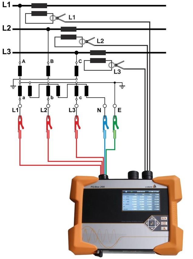
10.1.4 Connection to secondary transformer
Connections
Ensure that voltage measurement cable E is connected for every measurement.
If no PE connection is available, connect E and N together.
Ensure that switching (3-wire) is selected. (Setting via display or software)
Set the voltage transformer ratio
Enter the nominal conductor-conductor voltage
Set the current transformer ratio
In 3-wire connection the 4th voltage channel and the 4th current channel will be calculated from
the device. (Voltage Neutral to Ground and current of the star point)
26Special circuit types
Configurations such as a V connection or aron connection can be parameterized.
– V connection (parameterization through the evaluation software or device setup)
– Aron connection (parameterization through the evaluation software or device set-
up)
Isolated networks
Connections
Connect voltage measurement conductors E and N to ground
If this is not desired in the plant due to isolation monitoring, the E and N connections can be connect-
ed together and remain free without connection.
Ensure that switching (3-wire) is selected.
Set the voltage transformer ratio
Enter the nominal conductor-conductor voltage
Set the current transformer ratio
27We take care of it
11. Display
Pressing the right and left arrows on the directional pad changes the page of the
Display.
Display page 1
1 2 3 4
1) Recording "On" is indicated by a flashing red light
2) Display state of charge battery
state of charge >= 100% --> four green bars
state of charge >= 75% --> three green bars
state of charge >= 40% --> two green bars
state of charge >= 20% --> one red bar
state of charge < 20% --> empty
3) Current recording duration
4) Free space for recording / SD card size
Display page 2
→ Display the number of PQ events and fault recorder during the current measurement
28Display page 3
→ Display of the apparent, active and reactive power with sign prefix (individual phases and total per-
formance)
Display page 4
→ Display of the current and voltage THD (individual phases, neutral conductor)
→ Display of the conductor-conductor voltages
→ On the last two lines, the active and reactive power are displayed from the start of the measurement.
Display page 5
→ Date, time, version, current firmware version and time synchronization display.
→ After changing display pages once more, display page 1 appears again.
29We take care of it
Graphic display PQ-Box
With the keypad by pressing, "up" or "down" you get into the graphic screens.
Graphic display 1: Phasor diagram voltage and current
.
Scroll to the right or to the left with the keypad to reach the oscilloscope pictures.
Graphic display 2: oscilloscope voltage and current
Graphic display 3: oscilloscope voltage
Graphic display 4: oscilloscope current
With the “Enter” key it is possible to get back to the value view.
3011.1 Starting a measurement
Press the key to stop or start measuring.
- Recording "On" is indicated by a flashing red light
For a positive display of the active power
Ensure that the arrows on the current clamps point towards the consumer.
11.2 Manual Trigger
Press the key to set manual trigger.
→ Store the current voltages and currents with:
- Oscilloscope recorder
- 10ms RMS recorder
- Transient recorder (only PQ-Box 200 with option Transient)
The recording length and sampling frequency from transient measurement depends on the recorder
configuration selected in the software.
Example 3/4:
4 fault records were triggered while 3
fault records been stored on the SD card.
1) The number of the Oscilloscope record increases by 1.
2) The number of the RMS record increases by 1.
Example:
To evaluate the network perturbation of a consumer in the network:
Before starting the consumer, activate manual trigger.
After starting the consumer, activate manual trigger.
It is possible to compare all the images in the software. The images provide information about the
cause of the network perturbations
31We take care of it
11.3 Time synchronisation using the RS232 interface
→ The RS232 interface is equipped as standard for a DCF77 or GPS receiver connection.
- Automatic synchronisation of the measurement equipment after connecting receivers. If synchronisa-
tion is lost, the PQ-Box 200 runs with an internal quartz clock.
- A detected external clock is shown on the equipment display on display page 5.
Please start the measurement only after the initial synchronization is completed (this
may take a few minutes depending on the GPS signal strength).
11.4 PQ-Box 150 Setup
Press the key to open Setup.
Press this key again to exit the Setup Menu.
→ Display page changes to the Main Menu.
1) Change the network data parameters (measurement interval, nominal voltage, conversion
factors)
2) Basic equipment settings (display language, date, time)
3) TCP-IP interface settings
4) Change USB interface of PQ-Box to mass storage (very fast USB data transfer to PC)
32Parameterisation page 1
1) Freely adjustable measurement interval: 1 sec to 30 min (default interval setting = 600 sec)
Settings < 1 min should only be used for short measurements.
2) Switch between 1~; 3~ and 4~ conductor networks.
In a single phase network, only phase L1, neutral and earth will be measured.
In a 3-conductor system, all evaluations of the standard reports are calculated from the phase-
phase voltages.
In a 4-conductor system, all evaluations of the standard reports are calculated from the phase-
ground voltages.
Additional network types are: V-connection, split phase and delta high leg
3) Nominal voltage refers to the contractually agreed phase-to-phase voltage.
All recorders refer to this value as a percentage.
For the low voltage: 400 V applies.
4) Voltage converter corresponds to the ratio between the primary and secondary voltage.
scroll with the left/right control keys
Parameterisation page 2
1) Current converter corresponds to the ratio between the primary and secondary current.
2) Switch Aron connection for 2-current converter measurement on and off
33We take care of it
Changing parameters
Press .
→ the colour of the selected parameter changes to orange
Select position
→ the value can now be changed with the up and down arrows
Press to accept the changed value
→ the new value appears in the Menu
Settings page 1
1) Change the display language
2) Change the date
3) Change the time
4) Continuous mode (active = PQ-Box run permanent)
5) Memory limitation to 680 MB – active or no limitation of memory (Memory management)
3411.5 Keypad Lock
Press and hold the Setup key for > 5 sec while a measurement is in progress.
→ Keypad lock active.
Then press and hold > 5 sec.
→ Keypad lock inactive.
It is possible to see the measurement readings when the keypad is locked.
The Setup menu and screen pages are locked.
11.6 Password Protection and Interface Lock
In order to protect the PQ-box from unauthorized access and manipulation during measurement task
the device provides an interface lock mode with password (PIN) protection. The interface lock can be
activated in the setup menu and is protected with a corresponding four-digit numerical password, a PIN
consisting of any combination from 0000 to 9999.
The PIN (default factory setting is 0000) is set in the menu item Change PIN.
If the interface lock is active, the password protection locks the device automatically one minute after
starting a measurement. With the keypad lock function (see description above) the device can be locked
with password protection manually. In locked mode the USB and Ethernet interface are deactivated and
a display lock is active.
35We take care of it
In active interface lock mode the device can only be unlocked with the correct PIN.
After more than eleven incorrect PIN entries, user access is locked permanently and the
device has to be sent to the A. Eberle support address.
11.7 Memory management
So that the recorder data does not fill the whole memory when a too sensitive or incorrect trigger level
is set and thus the long-term recording is stopped, at the start of the measurement the PQ Box 200 re-
serves a maximum size of the free space for all fault records. If this memory size is reached, this can be
seen in the display by an asterisk * after the number of fault records.
e.g. Display: Oscilloscope recorder = 1312*
If the memory of the SC card is filled 100%, the message "Memory full“, appears in the display.
Two possibilities to run the memory management:
0 Memory limitation (680MB) = off
On single data file can get up to the maximum size of 3,41GB. If the data size is reached
then the PQ Box automatically starts a new measurement file. This will be repeated un-
til the maximum size of the microSD memory card is reached (f. e. 32 GByte). The size
of all recorders is limited to 1GB in one 3,41GB file.
Warning: This type needed for evaluating the 64bit WinPQ mobile software.
0 Memory limitation (680MB) = active
The PQ-Box memory size for one measurement file is limited to 680 MByte, to avoid
problems with Windows 32bit systems. If the data size is reached then the PQ Box au-
tomatically starts a new measurement file. This will be repeated until the maximum size
of the microSD memory card is reached (f. e. 32 GByte).
The size of all recorders is limited to 300 MB in one 680 MB file.
36The data converter provides the opportunity to connect several measurements to one measurement
file, if needed. (see chapter “Data Converter”)
11.8 Delete device memory
It is possible to clear the device memory of the PQ-Box using the front panel keys while the PQ-Box is
booting up.
Connect the power supply
If “A. Eberle logo” appears hold enter key for some seconds
→ Message appears: "Please press start button to clear the device memory"
Press record button
→ Device memory is formatted
→ PQ-Box is starting
11.9 Continuous mode without power supply
PQ-Box 200
If the function „continuous mode“ is active, the PQ box don´t stop running if the power supply is
pinched off. The PQ Box can work up to 6 hours with battery supply. You can start and stop records or
measure in online mode.
At 7% capacity, about 10 minutes before turning off, a warning message appears on the display.
Start without power supply
PQ-Box 150 can be started directly without power supply.
press start button > 10 seconds
→ PQ-Box 150 starts without power supply via battery.
→ PQ-Box 150 is now in the "Battery continuous operation“
Deactivate battery mode via the setup menu "Off".
37We take care of it
11.10 TCP-IP settings
In “Setup/ Ethernet Interface” you can change all parameters for IP interface.
In “Network mask” it is possible to switch between WLAN and LAN communication. Both ways of com-
munication can´t run at the same time.
This example shows the basic settings for the PQ Box 150 interface. All parameters can be changed with
the control keys on the box.
To accept the changed parameters, the device must be restarted
3811.11 WLAN Settings (Option for PQ-Box 150)
The display screen shows the basic setting of the WLAN configuration with the following parameters.
The IP address and subnet mask of the WLAN module can be set using the control pad.
Parameter Meaning
SSID Name of PQ-Box in network
WPA2-Key Password
IP-Address IP Address of PQ-Box
Subnet-mask Restriction of the DHCP address range
Please use the address range 2 to 99 in the 4th block of IP address.
WLAN Connection with WinPQ mobil software or PQ-Box App:
1 When the WLAN module is activated, the PQ box is displayed with its SSID in the wireless
network connections of your PC.
1 To establish a connection, the WPA2 key must be entered. SSID and password for a WPA2
connection can be found on the nameplate of the network analyzer. (Example: for „SSID:
PQBox150AP_1804-204“ the password would be „1804-204“).
The connection establishment may take a few seconds, as many PCs first try to establish an
Internet connection via the PQ-Box.
39We take care of it
12. PQ-Box App
Via an app for Android and IOS operating systems, all PQ boxes with integrated
WLAN/Wifi interface can be operated wirelessly. The app is available for free download in
the Apple App Store as well as in the Google Play Store.
A variety of online screens are available. All measuring devices can also be easily parameterized, e.g. via
a smartphone. A detailed parameterization of the PQ-Box (trigger limits, ripple control signal analysis,
...) is only possible via the WinPQ mobil software.
12.1 Connection to PQ-Box
The PQ-Box acts as a WLAN router. SSID and password for a WPA2 connection can be found on the
nameplate of the network analyzer. (Example: for „SSID: PQBox150AP_1804-204“ the password would
be „1804-204“)
O
4013. Maintenance/Cleaning
This unit is maintenance-free for customers.
Exceptions are the battery pack and micro-SD card, which can be accessed via the rear panel. The fuses
are in the voltage leads.
0 Open the housing cover by unscrewing the 6 screws on the back
Spare parts no.
0 SD memory card, 4GByte industry-standard 900.9099-4
0 Replacement battery pack 570.0010
0 Fuse for voltage leads; 500mA (FF) 30kA AC/DC; 1000V 6,3mmx32mm 582.1058
DANGER! Danger of electric shock!
Do not open the unit.
Maintenance of the equipment can only be carried out by A-Eberle.
For service, contact A-Eberle.
Service address:
A. Eberle GmbH & Co. KG
Frankenstraße 160
D-90461 Nuremberg
14. Calibration
We recommend a calibration interval of three years for the network analyzer PQ-Box 150 & 200 to
maintain the accuracy of GEFOR-made-IEC61000-4-30 Class A instruments.
15. Disposal
To dispose of the device and its accessories, send all components to A-Eberle.
41We take care of it
16. Product Warranty
0 A-Eberle guarantees that this product will remain free of defects in material and work-
manship for a period of three years from the date of purchase.
0 For accessories like current clamps and the battery the period is one year.
0 This warranty does not cover damage caused by accident, misuse or abnormal operat-
ing conditions.
To obtain service during the warranty period, please contact A-Eberle GmbH & Co KG in Nuremberg.
4243
We take care of it

A. Eberle GmbH & Co. KG

Frankenstraße 160
D-90461 Nuremberg

Tel.: +49-(0)911-62 81 08-0
Fax: +49 (0) 911 / 62 81 08-99
E-Mail: info@a-eberle.de
http://www.a-eberle.de

No. 584.0841

Vers. PQ Box 150 – 03/12/2020

44
You can also read