NYCe 4000 Multi-axis motion control system Standard Housings NY40x3 - Bosch Rexroth
←
→
Page content transcription
If your browser does not render page correctly, please read the page content below
NYCe 4000
Multi-axis motion control system
Standard Housings NY40x3

                                   Instructions   Edition 09
                                   R911337318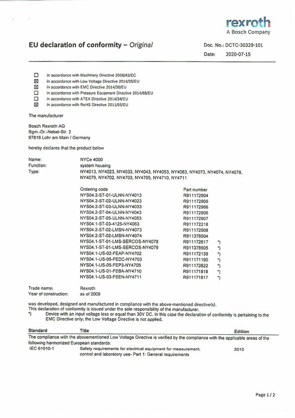
NYCe 4000 Multi-axis motion control
                                                                            system

List of trademarks
Products in this publication are referred to by their general trade names. In
most, if not all cases, these designations are claimed as trademarks or
registered trademarks of their respective companies.
Copyright
© Bosch Rexroth AG 2021
All rights reserved, also regarding any disposal, exploitation, reproduction,
editing, distribution, as well as in the event of applications for industrial
property rights.
Liability
The specified data is intended for product description purposes only and shall
not be deemed to be a guaranteed characteristic unless expressly stipulated in
the contract. All rights are reserved with respect to the content of this
documentation and the availability of the product.
Published by
Bosch Rexroth AG
P.O. Box 7170 ■ 5605 JD Eindhoven ■ The Netherlands
http://www.boschrexroth.com

                     RS-7e6badbd1592b2a00a347e865d191009-1-en-US-56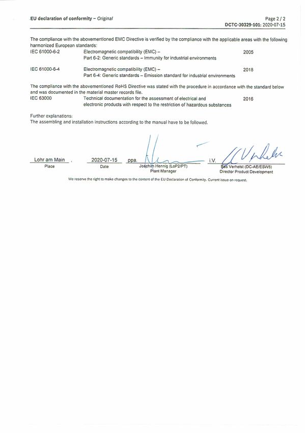
NYCe 4000 Multi-axis motion control                                                                       I
system                                                                                    Table of Contents

Table of Contents
                                                                                                              Page
1      About this Documentation.....................................................................                 1
1.1    Overview – target groups & product phases..........................................                           1
1.2    Intended audience.................................................................................            1
1.3    Availability..............................................................................................    1
1.4    Included parts........................................................................................        2
1.5    Variations...............................................................................................     2
1.6    Further available documentation...........................................................                    2
1.7    Additional parts.....................................................................................         2

2      Product Identification and Scope of Delivery........................................                          3
2.1    Product identification............................................................................            3
2.2    Scope of delivery...................................................................................          5

3      Using the Safety Instructions................................................................. 6
3.1    Safety instructions - structure............................................................... 6
3.2    Explaining signal words and safety alert symbols.................................. 6

4      Intended Use.......................................................................................... 7

5      Accessories, Spare Parts and Wear Parts.............................................. 7

6      Ambient Conditions...............................................................................             8

7      Technical Data........................................................................................        8
7.1    General..................................................................................................     8
7.2    24V Power supply ratings......................................................................                8
7.3    Drive power supply ratings....................................................................                9
7.4    Motor connector ratings........................................................................               9

8      Standards............................................................................................        10
8.1    Used standards....................................................................................           10
8.2    CE marking...........................................................................................        10
8.3    UL certification....................................................................................         11
8.4    China RoHS 2 marking.........................................................................                12

9      Interfacing............................................................................................ 13
9.1    Overview.............................................................................................. 13

                                                              R911337318_Edition 09 Bosch Rexroth AG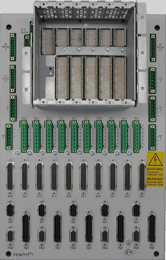
II                                                             NYCe 4000 Multi-axis motion control
Table of Contents                                                                          system

                                                                                                                  Page
9.2     24V System – Power supply connection..............................................                         14
9.3     SE – Service connection......................................................................              15
9.4     Fan – Fan connection...........................................................................            15
9.5     CAP – Capacitor connections..............................................................                  15
9.6     DP – Drive power supply connections.................................................                       16
9.7     M – Motor connections........................................................................              18
9.8     E – Encoder and HALL sensor connections.........................................                           19
9.9     An – Analog I/O connections...............................................................                 19
9.10    Fdig, Dig – 24V power supply for Fast digital I/O and Digital I/O con-
        nections...............................................................................................    20

10      Installation and Removal......................................................................             21
10.1    General................................................................................................    21
10.2    Mechanical dimensions........................................................................              21
10.3    Mechanical installation of the system housing....................................                          33
10.4    Protective Earth connection................................................................                34
10.5    Motor connection.................................................................................          34
10.6    Encoder connection.............................................................................            36
10.7    Configuration.......................................................................................       36
10.8    Mechanical removal of the system housing.........................................                          37

11      Commissioning....................................................................................          37

12      Description of the System Housing...................................................... 37

13      Diagnosis.............................................................................................     39

14      IT-security............................................................................................    39

15      Maintenance........................................................................................        39

16      Disposal...............................................................................................    40
16.1    Products..............................................................................................     40
16.2    Packaging materials.............................................................................           40
16.3    Environmental protection....................................................................               40

17      Service and Addresses......................................................................... 41
17.1    Service................................................................................................. 41
17.2    Addresses............................................................................................ 41

Bosch Rexroth AG R911337318_Edition 09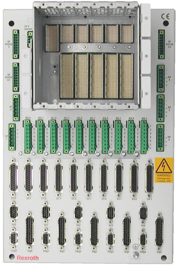
NYCe 4000 Multi-axis motion control                                                     III
system                                                                   Table of Contents

                                                                                         Page

18     Appendix – Declaration of Conformity................................................. 42

                                                  R911337318_Edition 09 Bosch Rexroth AG
IV                                       NYCe 4000 Multi-axis motion control
                                                                     system

Bosch Rexroth AG R911337318_Edition 09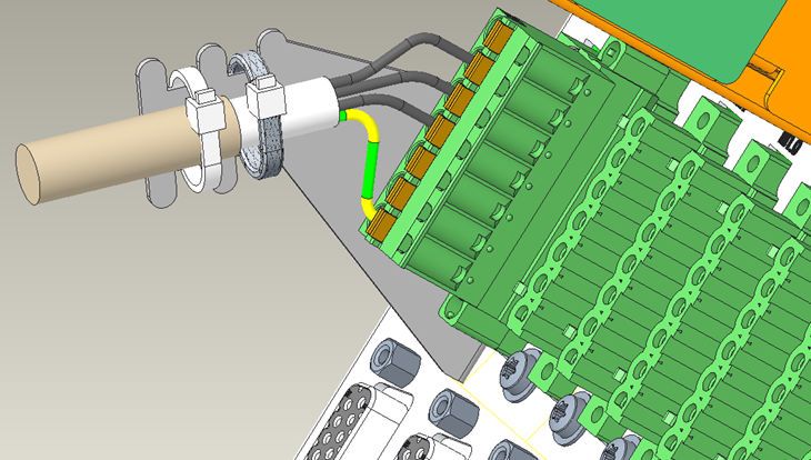
NYCe 4000 Multi-axis motion control                                                                        1/45
system                                                                                  About this Documentation

1 About this Documentation
1.1 Overview – target groups & product phases
The target groups, product phases and activities that can refer to this document
are marked in rounded boxes in the following figure.

 Product                         Mounting
              Selection                                   Engineering      Commissioning   Operation        Decommissioning
 phases                         (assembly/installation)

                      Presales Aftersales

              Design engineer
                                   Mechanic/
                                   electrician
               Programmer                                        Programmer
               Technologist                                Commissioning engineer
 Target          Process                                                            Technologist
 groups          specialist
                                                                                 Process specialist
                                                                                             Machine
                                                                                             operator
                                                                                           Maintenance        Mechanic/
                                                                                            technician        electrician
                                                                                              Service       Disposal company
                  Select             Unpack               Parameterize       Optimize         Operate         Dismount
                 Prepare               Mount                Program             Test         Maintain           Dispose
 Activities       Design               Install             Configure                          Remove
                                                                                               faults
                Construct                                   Simulate
                                                                                               Create
                                                                                           the NC program

Fig. 1-1: Target groups, product phases and activities

1.2 Intended audience
This document explains technical and service personnel of the machine builder
how to safely install the system housing mechanically and electrically. This
document is not the usage manual.

1.3 Availability
These Instructions are part of the NYS04.2-ST-0x-ULNN-NY40x3 system housing
product delivery (where x = 1, 2, 3, 4, 5) and must always be available for the
user. If the system housing is handed over to another person, these Instructions
must be handed over as well.

                                                                         R911337318_Edition 09 Bosch Rexroth AG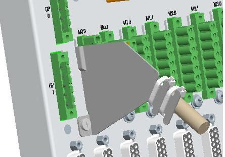
2/45                                              NYCe 4000 Multi-axis motion control
About this Documentation                                                      system

1.4 Included parts
Type code                                                  Material number   Description
One of
●   NYS04.2-ST-01-ULNN-NY4013                              R911172904        system housing
●   NYS04.2-ST-02-ULNN-NY4023                              R911172905        system housing
●   NYS04.2-ST-03-ULNN-NY4033                              R911172966        system housing
●   NYS04.2-ST-04-ULNN-NY4043                              R911172906        system housing
●   NYS04.2-ST-05-ULNN-NY4053                              R911172907        system housing
DOK-NY4000-SYST*40X3**-IT09-EN-P                           R911337318        Instructions

Tab. 1-1: Available system housings

Headers for 24V System, SE, DP NY4130, DP and M connectors are also
included.

1.5 Variations
These Instructions apply to the NYCe 4000 system housings with the following
type code:
●   NYS04.2-ST-01-ULNN-NY4013
●   NYS04.2-ST-02-ULNN-NY4023
●   NYS04.2-ST-03-ULNN-NY4033
●   NYS04.2-ST-04-ULNN-NY4043
●   NYS04.2-ST-05-ULNN-NY4053

1.6 Further available documentation
The following documentation contains detailed information. Use the listed
documentation or a newer version, if available.
Title and type code                                                      Material number
Rexroth NYCe 4000 Hardware System Manual
                                                                         R911337671
DOK-NY4000-HW***SYSTEM-PRRS-EN-E
Rexroth NYCe 4000 Standard Housings & Accessories Manual
                                                                         R911337672
DOK-NY4000-HOUSING*ACC-PRRS-EN-E

Tab. 1-2: Available documentation

1.7 Additional parts
Motion Control Units, host adapter, drive modules, fan units, capacitor kits,
connection cables, and more are listed in the project planning manuals or on
www.boschrexroth.com.

Bosch Rexroth AG R911337318_Edition 09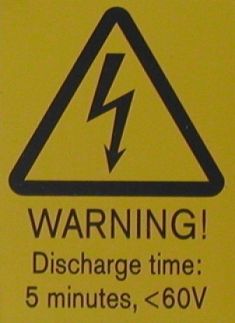
NYCe 4000 Multi-axis motion control                                       3/45
system                             Product Identification and Scope of Delivery

2 Product Identification and Scope of Delivery
2.1 Product identification
All system housings have one slot for the Motion Control Unit (MCU) and the
●   NYS04.2-ST-01-ULNN-NY4013 has one slot for a drive module.
●   NYS04.2-ST-02-ULNN-NY4023 has 2 slots for drive modules.
●   NYS04.2-ST-03-ULNN-NY4033 has 3 slots for drive modules.
●   NYS04.2-ST-04-ULNN-NY4043 has 4 slots for drive modules.
●   NYS04.2-ST-05-ULNN-NY4053 has 5 slots for drive modules.

Fig. 2-1: View of the NYS04.2-ST-05-ULNN-NY4053

The Power Marking label indicates the rating of the system housing and other
information.

                                              R911337318_Edition 09 Bosch Rexroth AG
4/45 NYCe 4000 Multi-axis motion control
Product Identification and Scope of Delivery system
1 2 3
TYP:
14 MNR: 4
POWER INPUT
Bosch Rexroth AG Bgm.-Dr.-Nebel-Str. 2, D-97816 Lohr a. Main
5
IP20 6
13 I-C-B-H-T-V
12 7
11
FD: 15W12
10 9 8
Fig. 2-2: Power marking label
1 Logotype
2 Type code
3 Division number / plant number
4 Change index
Bosch Rexroth AG R911337318_Edition 09NYCe 4000 Multi-axis motion control 5/45
system Product Identification and Scope of Delivery
5 Rated voltages and currents
6 Degrees of protection provided by enclosure (IP code)
7 Designation of origin
8 Date of manufacture (yyWww)
9 Rexroth bar code
10 Serial number
11 Company address
12 Certification markings
13 Test markings
14 Material number
Tab. 2-1: Power marking labels and explanation
The discharge warning label warns the technician to observe a 5 minute
discharge time delay to be certain that voltages are below 60 V, before
undertaking any actions with the product.
Fig. 2-3: Warning label
Consult the documentation for detailed information.
Fig. 2-4: Documentation label
Tab. 2-2: Labels on the system housing
2.2 Scope of delivery
The product delivery consists of the following items.
● NYS04.2-ST-01-ULNN-NY4013 system housing, material number R911172904
or
NYS04.2-ST-02-ULNN-NY4023 system housing, material number R911172905
R911337318_Edition 09 Bosch Rexroth AG6/45 NYCe 4000 Multi-axis motion control
Using the Safety Instructions system
or
NYS04.2-ST-03-ULNN-NY4033 system housing, material number R911172966
or
NYS04.2-ST-04-ULNN-NY4043 system housing, material number R911172906
or
NYS04.2-ST-05-ULNN-NY4053 system housing, material number R911172907
● DOK-NY4000-SYST*40X3**-IT09-EN-P Instructions, material number
R911337318.
● Cable connector parts for 24V System, SE, Drive Power and Motor
connections.
3 Using the Safety Instructions
3.1 Safety instructions - structure
The safety instructions are structured as shown in the following example.
Fig. 3-1: Safety instruction lay-out
3.2 Explaining signal words and safety alert symbols
The safety instructions in this documentation contain specific signal words
(danger, warning, caution, notice) and if necessary, a safety alert symbol
(according to ANSI Z535.6-2011).
The signal word is meant to draw the reader’s attention to the safety instruction
and signifies the degree of danger. The safety alert symbol (a triangle with an
exclamation point), which precedes the signal words "danger", "warning" and
"caution" is used to alert the reader to personal injury hazards.
DANGER In case of non-compliance with this safety
instruction, death or serious injury will occur.
Bosch Rexroth AG R911337318_Edition 09NYCe 4000 Multi-axis motion control 7/45
system Accessories, Spare Parts and Wear Parts
WARNING In case of non-compliance with this safety
instruction, death or serious injury can occur.
CAUTION In case of non-compliance with this safety
instruction, minor or moderate injury could
occur.
NOTICE In case of non-compliance with this safety
instruction, property damage could occur.
4 Intended Use
The system housing is for indoor use only, and may only be used with parts
indicated in this document. Not explicitly mentioned parts may not be installed
or connected. Usage is only allowed in explicitly indicated combinations of
parts.
Do not install and use this system housing before you have read all relevant
documents. You must read the safety instructions and all other directions for
use before you start any work or activity with this system housing.
The system housing has no certified functional safety on board. This means that
all precautions for a safe operation must be ensured by external components.
5 Accessories, Spare Parts and Wear Parts
The following accessories are available for these system housings.
Type code Material number Description
NYA04.1-FAN-1DRV-NY4922/00 R911328062 Fan unit – 1 drive slot
NYA04.1-FAN-2DRV-NY4922/10 R911325083 Fan unit – 2 drive slots
NYA04.1-FAN-3DRV-NY4922/20 R911172220 Fan unit – 3 drive slots
NYA04.1-FAN-4DRV-NY4922/30 R911328063 Fan unit – 4 drive slots
NYA04.1-FAN-5DRV-NY4922/50 R911325084 Fan unit – 5 drive slots
NYA04.1-CAP-100V-NY4921/00 R911325079 Capacitor kit 100V
NYA04.1-CAP-200V-NY4921/10 R911325082 Capacitor kit 200V
NYA04.1-COVRPL-NO-USED-NY4900 R911318964 Cover plate for non-used slots
Motor cable shield and support
NYA04.1-SHIELD-SUP-MOT-5PCS-NY491 R911172999
bracket
Tab. 5-1: Accessories for system housings
R911337318_Edition 09 Bosch Rexroth AG8/45 NYCe 4000 Multi-axis motion control
Technical Data system
The system housings do not contain any replaceable or wear parts. In case of
failure, the entire system housing must be replaced.
6 Ambient Conditions
Operating Storage and transport
Maximum environment
+5 °C .. +55 °C -40 °C .. +85 °C
temperature
Relative Humidity 10 % .. 90 % (non-condensing) 5 % .. 95 % (non-condensing)
Vibration: IEC 60068-2-6:2007
Mechanical strength Vibration, broad-band: Shock: IEC 60068-2-27:2008
IEC 60068-2-64:2008
Pollution degree 2 2
Overvoltage category II -
Maximum altitude 4000 m
Tab. 6-1: Ambient conditions
Degrees of protection provided by enclosures: IP20.
Free air flow in vertical direction is required above and below the system
housing for a distance of minimal 10 cm for forced cooled systems and 20 cm
for convection cooled systems.
If convection cooling is used (instead of forced cooling) the system housing
must be installed vertical to ensure sufficient free air flow through the
ventilation holes. In particular, bend cables away from the ventilation holes as
near to the connectors as possible.
7 Technical Data
7.1 General
Requirements on Mains Circuits.
● Mains Circuits of overvoltage category II up to 300 V AC rms.
7.2 24V Power supply ratings
The 24V System, 24V Fast Digital and 24V Digital input power specifications are
listed in the following table.
Bosch Rexroth AG R911337318_Edition 09NYCe 4000 Multi-axis motion control 9/45
system Technical Data
Input power UN IN IN
Fan Natural convection
24V System DC 24V 3.0A 3.0A
24V Fdigx DC 24V 4.5A 4.5A
24V Digx DC 24V 4.5A 4.5A
Tab. 7-1: 24V power supply ratings
7.3 Drive power supply ratings
The drive power specifications for the system housing are listed in the following
table.
Drive power UN IN IN
Fan Natural convection
DC +15 .. +75V 12.0A 6.0A
DPx
DC +48 .. +150V 6.0A 2.5A
DC +26V/–26V 1.0A 0.5A
DP NY4130 x
DC +15V/–15V 1.7A 1.0A
Tab. 7-2: Drive power supply ratings
7.4 Motor connector ratings
The motor connector ratings for the NY4120 and NY4140 modules (DPx) are
specified in the following tables.
● Motor connector Mx.0
Motor type UN IN IN
Fan Natural convection
BLAC motor DC 3x 0V .. 150V 0 .. 7Arms 0 .. 3Arms
BLDC motor DC 3x 0V .. 150V 0 .. 7Arms 0 .. 3Arms
Stepper motor DC 4x 0V .. 75V 0 .. 7Arms 0 .. 3Arms
DC motor DC 2x 0V .. 75V 0 .. 7Arms 0 .. 3Arms
Tab. 7-3: Motor connector Mx.0 ratings
● Motor connector Mx.1
Motor type UN IN IN
Fan Natural convection
BLAC motor DC 3x 0V .. 75V 0 .. 7Arms 0 .. 3Arms
BLDC motor DC 3x 0V .. 75V 0 .. 7Arms 0 .. 3Arms
R911337318_Edition 09 Bosch Rexroth AG10/45 NYCe 4000 Multi-axis motion control
Standards system
Motor type UN IN IN
Fan Natural convection
Stepper motor DC 4x 0V .. 75V 0 .. 7Arms 0 .. 3Arms
DC motor DC 2x 0V .. 75V 0 .. 7Arms 0 .. 3Arms
Tab. 7-4: Motor connector Mx.1 ratings
The motor connector ratings for the NY4130 (DP NY4130 x) are specified in the
following tables.
● Motor connector Mx.0
Motor type UN IN IN
and connection Fan Natural convection
DC motor balanced DC 0V .. 48V 0 .. 2Arms 0 .. 1Arms
Tab. 7-5: Motor connector Mx.0 ratings
● Motor connector Mx.1
Motor type UN IN IN
and connection Fan Natural convection
DC motor unbalanced DC 0V .. 24V 0 .. 2Arms 0 .. 1Arms
Tab. 7-6: Motor connector Mx.1 ratings
8 Standards
8.1 Used standards
The components of the system housing correspond to the following standard.
● IEC61010-1:2010 (Safety requirements for electrical equipment for
measurement, control and laboratory use - Part 1: General requirements)
● IEC61000-6-2:2005) (Immunity for industrial environments)
● IEC61000-6-4:2018 (Emission for industrial environments)
8.2 CE marking
Declaration of Conformity
Fig. 8-1: CE logo
Bosch Rexroth AG R911337318_Edition 09NYCe 4000 Multi-axis motion control 11/45
system Standards
The system housings described in the present instructions, comply with the
requirements and the target of the following EU directive and with the following
harmonized European standards:
● Low Voltage Directive 2014/35/EU
This product is a built-in unit which, owing to its installation characteristics, is
not able to comply with the regulations for complete apparatus, machines or
installations from the outset. For this reason, it may only be used for built-in
purposes. The product may only be assessed with regard to its electrical and
mechanical safety as well as to environmental effects (foreign bodies, moisture)
after it has been installed in the product intended for the final user. After the
product has been installed, its EMC properties may change. Hence the product
intended for the final user (complete apparatus, machines or installations)
should be inspected with regard to its EMC properties by the manufacturer of
the product intended for the final user.
● EMC Directive 2014/30/EU
Maintaining the EMC directive presuppose an EMC adapted installation of the
devices within the installation of the machine. The complied limit values and
standards are specified in the Rexroth Manual of associated product. The
regulations for the structure and the installation in this manual must be
maintained and realized. Tests were run using a typical installation in a test
assembly that conforms with the standards. These Rexroth products are built-in
devices for a product for the final user. The test results cannot be transferred to
every state as installed in every product intended for the final user. This
declaration does not therefore assure the EMC characteristics of the product for
the final user.
8.3 UL certification
Fig. 8-2: UL Listed logo
The system housings
● NYS04.2-ST-01-ULNN-NY4013
● NYS04.2-ST-02-ULNN-NY4023
● NYS04.2-ST-03-ULNN-NY4033
● NYS04.2-ST-04-ULNN-NY4043
● NYS04.2-ST-05-ULNN-NY4053
are certified according to
R911337318_Edition 09 Bosch Rexroth AG12/45 NYCe 4000 Multi-axis motion control
Standards system
● UL 61010-1:2012
UL file no. E353498
However, there can exist combinations with modules or accessories with limited
or missing certification. Therefore, verify the registration according to the UL
marking on the device.
NOTICE Loss of UL conformity due to changes to the
system housing.
The UL marking is only valid for the system housing in its delivery status. After
any modification by the customer to the system housing the UL compliance is to
be verified.
8.4 China RoHS 2 marking
Fig. 8-3: China RoHS 2 logo
The system housings
● NYS04.2-ST-01-ULNN-NY4013
● NYS04.2-ST-02-ULNN-NY4023
● NYS04.2-ST-03-ULNN-NY4033
● NYS04.2-ST-04-ULNN-NY4043
● NYS04.2-ST-05-ULNN-NY4053
comply with the requirements of the Administrative Measures for the Restriction
of the Use of Hazardous Substances in Electrical and Electronic Products,
known as China RoHS 2.
Bosch Rexroth AG R911337318_Edition 09NYCe 4000 Multi-axis motion control 13/45
system Interfacing
9 Interfacing
9.1 Overview
Designation Connection type Connection Connection
on base plate (base plate) (cable)
24V DC system Phoenix Contact
24V System 3-pin male
power supply MC 1,5/ 3-STF-3,5
Phoenix Contact
SE Service inputs 4-pin male
MC 1,5/ 4-STF-3,5
Fan System fan unit 2-pin male
CAP 0
CAP 1
Filter capacitor
CAP 2 2-pin male
for each drive slot
CAP 3
CAP 4
DP NY4130 0 (note 1) NY4130 drive power slot 0
DP NY4130 0/1 NY4130 drive power slot 0/1
Phoenix Contact
DP NY4130 2 NY4130 drive power slot 2 8-pin male
MC 1,5/ 8-STF-3,5
DP NY4130 2/3 (note 2) NY4130 drive power slot 2/3
DP NY4130 3/4 NY4130 drive power slot 3/4
DP 0
NY4120
DP 1
NY4140 Phoenix Contact
DP 2 5-pin male
drive power MSTB 2,5/ 5-STF-5,08
DP 3
for each drive slot
DP 4
M0.0 M0.1
M1.0 M1.1
Motor connector Phoenix Contact
M2.0 M2.1 7-pin male
2 connectors for each slot IC 2,5/ 7-STF-5,08
M3.0 M3.1
M4.0 M4.1
E0.0 E0.1
E1.0 E1.1 25-pin sub-D
Encoder connector female with 25-pin sub-D male
E2.0 E2.1
2 connectors for each slot 4-40 UNC with 4-40 UNC screws
E3.0 E3.1 nuts
E4.0 E4.1
R911337318_Edition 09 Bosch Rexroth AG14/45 NYCe 4000 Multi-axis motion control
Interfacing system
Designation Connection type Connection Connection
on base plate (base plate) (cable)
An0
An1 9-pin sub-D
Analog I/O connector male with 9-pin sub-D female
An2
1 connector for each slot 4-40 UNC with 4-40 UNC screws
An3 nuts
An4
Fdig0
Fdig1 9-pin sub-D
Fast digital I/O connector female with 9-pin sub-D male
Fdig2
1 connector for each slot 4-40 UNC with 4-40 UNC screws
Fdig3 nuts
Fdig4
Dig0
Dig1 25-pin sub-D
Digital I/O connector male with 25-pin sub-D female
Dig2
1 connector for each slot 4-40 UNC with 4-40 UNC screws
Dig3 nuts
Dig4
Protective earth M5 threaded
connection screw
note 1 The text “DP NY4130 0” is only on the NYS04.2-ST-01-ULNN-NY4013.
note 2 The text “DP NY4130 2/3” is only on the NYS04.2-ST-04-ULNN-NY4043.
Tab. 9-1: System housing connections
9.2 24V System – Power supply connection
The connector "24V SYSTEM" connects the 24V power supply to the system
housing for all modules in the module holder.
NOTICE The system housing has no provisions against
wrong polarity connection of the 24V System
power supply.
Observe the correct polarity of the power supply connections.
Connect the minus at the power supply side of the cable to the housing and/or
to protective earth (if this is not already the case). If the cable has a shield,
connect the shield at the system housing side to the shield pin in the connector
or the connector housing, and connect the shield on the other side of the cable
to the housing of the power supply.
Bosch Rexroth AG R911337318_Edition 09NYCe 4000 Multi-axis motion control 15/45
system Interfacing
Make sure that the power supply cable diameter is suitable for the maximum
rated current
Connector data MC 1,5/ 3-STF-3,5 minimum maximum
Tightening torque 1,95 lbs*inch (0,22 Nm) 2,21 lbs*inch (0,25 Nm)
Wire diameter 30 AWG (0,14 mm2) 14 AWG (1,5 mm2)
Tab. 9-2: 24V System connector information
9.3 SE – Service connection
The connector "SE" are inputs to set the operation mode of the system to
“service mode” and to execute an as fast as possible shutdown, called “stop
axes”
Connector data MC 1,5/ 4-STF-3,5 minimum maximum
Tightening torque 1,95 lbs*inch (0,22 Nm) 2,21 lbs*inch (0,25 Nm)
Wire diameter 30 AWG (0,14 mm2) 14 AWG (1,5 mm2)
Tab. 9-3: SE Service connector information
9.4 Fan – Fan connection
The connector "FAN" is a power supply connector for the fan unit that can be
installed underneath the module holder for forced cooling.
9.5 CAP – Capacitor connections
One capacitor connection is available for each slot of the system housing.
WARNING Voltage on the pins of this connector can be
higher than 60V DC.
Do not touch the pins of this connector. Do not touch the rear side of the I/O
backplane .
A capacitor may only be needed if the drive module installed in a slot is an
NYM04.1-2PW-NNNN-NY4120 or NYM04.1-1HV-NNNN-NY4140.
CAUTION Maximum drive power voltage for the installed
drive module must be lower than the working
voltage of the installed capacitor.
Make sure that a capacitor with correct ratings is installed.
R911337318_Edition 09 Bosch Rexroth AG16/45 NYCe 4000 Multi-axis motion control
Interfacing system
NOTICE The system housing has no provisions against
wrong polarity connection of the capacitor.
Observe the correct polarity of the connection of the DP drive power header.
No capacitor is needed if the drive slot contains an NYM04.1-2LD-NNNN-NY4130
or NYM04.1-SE3-MAST-NY4150 module.
9.6 DP – Drive power supply connections
Two different drive power supply connectors are on the base plate of the system
housing.
1. Drive power supply for drive module NYM04.1-2LD-NNNN-NY4130
Connectors: "DP NY4130 0", "DP NY4130 0/1", "DP NY4130 2", "DP NY4130
2/3", "DP NY4130 3/4". Maximum voltages: +/–29V DC.
2. Drive power supply for drive modules NYM04.1-2PW-NNNN-NY4120 and
NYM04.1-1HV-NNNN-NY4140.
Connectors: "DP0", "DP1", "DP2", "DP3", "DP4". Maximum voltage: +150V
DC .
DANGER Voltage on the pins of this connector can
be higher than 60V DC. When the
connector is unplugged a high voltage can
remain present on the pins for 5 minutes
after disconnection. If the drive slot has an
accompanying capacitor installed and the
drive module is not installed in that slot,
you must wait 30 minutes.
Do not touch the pins of this connector.
Do not touch the rear side of the I/O backplane.
NOTICE The system housing has no provisions against
wrong polarity connection of the DP and DP
NY4130 power supply.
Observe the correct polarity of the drive power supply connections.
If the cable has a shield, connect the shield at the system housing side to the
shield pin in the connector or the connector housing. It is recommended that
the shield of the cable at the power supply side is connected to the chassis of
the power supply unit, not to the PE connection.
Bosch Rexroth AG R911337318_Edition 09NYCe 4000 Multi-axis motion control 17/45
system Interfacing
All drive power cables must be installed with some form of a strain relief
underneath the system housing. If the drive power cable has a shielding, this
shielding must make a good quality electrical contact with the strain relief
bracket.
Make sure that the power supply cable diameter is suitable for the maximum
rated current.
If the drive power supply for the drive modules NYM04.1-2PW-NNNN-NY4120
and NYM04.1-1HV-NNNN-NY4140 is not installed near the system housing, put a
warning on the connector at the drive power supply side stating that when the
connector is disconnected a high voltage can remain present on the pins of the
connector for 5 minutes.
A fuse must be installed between the power supply output voltage and the drive
power input voltage connection. The rating of the fuse depends on the used
cables and application requirements of the motion profiles.
● Fuse rating for UL fuses.
Drive module Drive current [DC] Fuse nominal DC current
NY4120 12A 15A
NY4130 (+26/–26V power supply) 1A 2A
NY4130 (+15/–15V power supply) 2A 3A
NY4140 6A 8A
Tab. 9-4: UL Fuse ratings
Fuses must be certified for DC rating, Fast Acting, and have to be UL recognized
under CCN JDXY2/8. Secondary fuses also have to be UL certified for DC rating.
● Fuse rating for IEC fuses.
Drive module Drive current [DC] Fuse nominal DC current
NY4120 12A 12A
NY4130 (+26/–26V power supply) 1A 1A
NY4130 (+15/–15V power supply) 2A 2A
NY4140 6A 6A
Tab. 9-5: IEC Fuse ratings
Fuses must be certified for DC rating, Fast Acting, and have to be IEC 60127-1
certified. Secondary fuses also have to be or IEC certified for DC rating.
Wire gauge and wire diameter as a function of ambient temperature are derived
from the NFPA-79:2012. Insulation temperature of wires is assumed to be 60 °C
(140°F) or 75°C (167°F).
R911337318_Edition 09 Bosch Rexroth AG18/45 NYCe 4000 Multi-axis motion control
Interfacing system
Connector data MSTB 2,5/ 5-STF-5,08 minimum maximum
Tightening torque 4,43 lbs*inch (0,5 Nm) 5,31 lbs*inch (0,6 Nm)
Wire diameter 26 AWG (0,2 mm2) 12 AWG (2,5 mm2)
Tab. 9-6: DP connector information
Connector data MC 1,5/ 8-STF-3,5 minimum maximum
Tightening torque 1,95 lbs*inch (0,22 Nm) 2,21 lbs*inch (0,25 Nm)
Wire diameter 30 AWG (0,14 mm2) 14 AWG (1,5 mm2)
Tab. 9-7: DP NY4130 connector information
If using wires with an AWG smaller than or equal 12, or a diameter larger than or
equal 2 mm2, two pins for (+) and two pins for (–) must be used on the drive
power connector.
9.7 M – Motor connections
WARNING Voltage on the pins of this connector can be
higher than 60V DC.
Do not touch the pins of this connector.
Do not touch the rear side of the I/O backplane.
Always use shielded cables for motors connected to NYM04.1-2PW-NNNN-
NY4120 and NYM04.1-1HV-NNNN-NY4140 drive modules. Shielded cables for
motors connected to NYM04.1-2LD-NNNN-NY4130 drive modules are not
mandatory, but recommended.
Make sure that the motor cable of suitable AWG marking is used, taking into
account the number of separate wires in the cable and the maximum rated
current.
Every motor cable must be connected on the system housing with a motor cable
shield and support bracket.
Connect the shield at the system housing side to the motor cable shield and
support bracket, and connect the shield at the other end to the motor housing.
If the housing of the connector at the motor side is made of non-conducting
material, connect the shield from the connector at the end of the cable coming
from the system housing side to the metal mounting plate on which that motor
is mounted.
Wire gauge and wire diameter as a function of ambient temperature are derived
from the NFPA-79:2012. Insulation temperature of wires is assumed to be 60°C
(140°F) or 75°C (167°F).
Bosch Rexroth AG R911337318_Edition 09NYCe 4000 Multi-axis motion control 19/45
system Interfacing
Connector data IC 2,5/ 7-STF-5,08 minimum maximum
Tightening torque 4,43 lbs*inch (0,5 Nm) 5,31 lbs*inch (0,6 Nm)
Wire diameter 24 AWG (0,2 mm2) 12 AWG (2,5 mm2)
Tab. 9-8: M connector information
9.8 E – Encoder and HALL sensor connections
Always use shielded cables. Connect the shield at the system housing side to
the connector housing. If the equipment on the other end has metal parts,
connect the shield to the equipment housing. If the equipment on the other end
does not have metal parts, connect the shield to the equipment ground.
● Encoder interfaces
If the encoder interface has open-collector drivers, include a pull-up resistor
of for example 1 kΩ between each signal and the 5V_ENC connection.
● Encoder or HALL sensor interfaces.
If the encoder or HALL sensor interface has single-ended drivers, connnect
the negative input of each signal pair in the connector at the system housing
to the reference voltage EncVref.
9.9 An – Analog I/O connections
Always use shielded cables. Connect the shield at the system housing side to
the connector housing. If the equipment on the other end has metal parts,
connect the shield to the equipment housing. If the equipment on the other end
does not have metal parts, connect the shield to the equipment ground.
All external connected inputs and outputs shall be separated from hazardous
live by double or reinforced insulation.
● Analog inputs
If the analog source provides a single-ended signal, connect the signal wire to
the positive input at the system housing, and connect the equipment ground
to the negative pin at the system housing. If the analog source provides a
balanced differential signal, connect the signal wires to the corresponding
input pins at the system housing. It may also be desirable to connect a
termination resistor between the signal wires at the system housing. Consult
the supplier’s installation instructions.
● Analog outputs
If the analog input at the destination equipment accepts a differential signal
(preferred), connect the positive input to the analog output at the system
housing, and connect the negative input to the AGND pin in the connector at
the system housing.
Make sure that at the destination equipment some resistive path is present
for equalization current, for example 100 kΩ between the negative input and
local ground. If this resistance or some equivalent is not included in the
R911337318_Edition 09 Bosch Rexroth AG20/45 NYCe 4000 Multi-axis motion control
Interfacing system
equipment itself, install it in the connector at the equipment side of the
cable.
If the analog input at the destination equipment only accepts a single-ended
signal (not recommended), connect the input to the analog output at the
system housing, and connect the ground of the destination equipment to the
AGND pin in the connector at the system housing via a 100Ω resistor. Note
that this resistor connects the internal ground of the system housing to the
internal ground of the destination equipment. A resistor in this ground
connection is recommended to prevent unwanted stray currents. However,
this resistor may well influence the accuracy of the analog signal.
Never connect the GND or minus wire of these signals to other GND
connections, otherwise malfunction of the module is possible.
9.10 Fdig, Dig – 24V power supply for Fast digital I/O and Digital
I/O connections
The 24V SELV power supply for the fast digital I/O and all digital I/O connections
are on the connectors "DIG", "FDIG" and "DIG/FDIG".
NOTICE The system housing has no provisions against
wrong polarity connection of the 24V I/O power
supply voltage.
Observe proper polarity when connecting the 24V I/O power supply.
A fuse must be installed between the 24V SELV power supply output voltage and
the 24V I/O power input voltage. The rating of the fuse depends on the used
cables and total current.
Current [DC] UL recognized fuse IEC certified fuse
[nominal DC current] [nominal DC current]
4.5A 6A 5A
Tab. 9-9: Fuse ratings for 24V power supply (Fast digital I/O and Digital I/O)
Fuses must be certified for DC rating, Fast Acting, and have to be UL recognized
under CCN JDXY2/8 or IEC 60127-1 certified. Secondary fuses also have to be
UL or IEC certified for DC rating.
Wire gauge and wire diameter as a function of ambient temperature are derived
from the NFPA-79:2012. Insulation temperature of wires is assumed to be 60 °C
(140 °F) or 75 °C (167 °F)
All external connected inputs and outputs shall be separated from hazardous
live by double or reinforced insulation.
Bosch Rexroth AG R911337318_Edition 09NYCe 4000 Multi-axis motion control 21/45
system Installation and Removal
Shielded cables are mandatory for fast digital I/O connections. Shielded cables
are recommended but not mandatory for digital I/O connections. If shielded
cables are used, connect the shield at the system housing side to the connector
housing. Connect the other end to a convenient metal part or leave it not
connected.
For fast digital I/O signals, the cable with the signal wire(s) should also contain
the return current path for every signal in the cable. It is allowed that a single
wire carries the return currents for more than one signal, as long as the current
rating of the wire is not exceeded. These measures are also recommended for
the other digital I/O.
10 Installation and Removal
10.1 General
NOTICE Damage to components may occur if power is
applied during installation or removal.
● Make sure power supplies are switched off before installation or removal of
the system housing.
● Do not apply power until the system housing is installed.
Power supplies must be switched on/off with the disconnecting device installed
in the cabinet.
The system housing may only be used as build-in equipment in a cabinet, which
means that the end-user must provide a suitable fire and electrical safe
enclosure. The safety of any system incorporating the system housing is the
responsibility of the assembler of the system.
The system housing may only be used in combination with external approved
power supplies. The supply voltages 24V System, DP NY4130, 24V Dig, and 24V
Fdig for the system must be separated at least by reinforced insulation from all
hazardous voltages according to the standard UL61010-1 third edition.
10.2 Mechanical dimensions
The dimensions of the system housings are the following.
Type code Width (mm) Height (mm) Depth (mm)
NYS04.2-ST-01-ULNN-NY4013 130 225 157.9
NYS04.2-ST-02-ULNN-NY4023 180 240 157.9
NYS04.2-ST-03-ULNN-NY4033 183 353.5 157.9
R911337318_Edition 09 Bosch Rexroth AG22/45 NYCe 4000 Multi-axis motion control Installation and Removal system Type code Width (mm) Height (mm) Depth (mm) NYS04.2-ST-04-ULNN-NY4043 208 353.5 157.9 NYS04.2-ST-05-ULNN-NY4053 238 353.5 157.9 Tab. 10-1: System housings mechanical dimensions You can see the dimensions of the system housings in the following views. The dimensions given in the view exclude free clearance space required for attached cables, accessories and cooling requirements. Bosch Rexroth AG R911337318_Edition 09
NYCe 4000 Multi-axis motion control                                             23/45
system                                                       Installation and Removal

Fig. 10-1: Dimensions (front view) of the NYS04.2-ST-01-ULNN-NY4013

                                               R911337318_Edition 09 Bosch Rexroth AG
24/45 NYCe 4000 Multi-axis motion control Installation and Removal system Fig. 10-2: Dimensions (side view) of the NYS04.2-ST-01-ULNN-NY4013 Bosch Rexroth AG R911337318_Edition 09
NYCe 4000 Multi-axis motion control                                             25/45
system                                                       Installation and Removal

Fig. 10-3: Dimensions (front view) of the NYS04.2-ST-02-ULNN-NY4023

                                               R911337318_Edition 09 Bosch Rexroth AG
26/45 NYCe 4000 Multi-axis motion control Installation and Removal system Fig. 10-4: Dimensions (side view) of the NYS04.2-ST-02-ULNN-NY4023 Bosch Rexroth AG R911337318_Edition 09
NYCe 4000 Multi-axis motion control                                             27/45
system                                                       Installation and Removal

Fig. 10-5: Dimensions (front view) of the NYS04.2-ST-03-ULNN-NY4033

                                               R911337318_Edition 09 Bosch Rexroth AG
28/45 NYCe 4000 Multi-axis motion control Installation and Removal system Fig. 10-6: Dimensions (side view) of the NYS04.2-ST-03-ULNN-NY4033 Bosch Rexroth AG R911337318_Edition 09
NYCe 4000 Multi-axis motion control                                             29/45
system                                                       Installation and Removal

Fig. 10-7: Dimensions (front view) of the NYS04.2-ST-04-ULNN-NY4043

                                               R911337318_Edition 09 Bosch Rexroth AG
30/45 NYCe 4000 Multi-axis motion control Installation and Removal system Fig. 10-8: Dimensions (side view) of the NYS04.2-ST-04-ULNN-NY4043 Bosch Rexroth AG R911337318_Edition 09
NYCe 4000 Multi-axis motion control                                             31/45
system                                                       Installation and Removal

Fig. 10-9: Dimensions (front view) of the NYS04.2-ST-05-ULNN-NY4053

                                               R911337318_Edition 09 Bosch Rexroth AG
32/45 NYCe 4000 Multi-axis motion control Installation and Removal system Fig. 10-10: Dimensions (side view) of the NYS04.2-ST-05-ULNN-NY4053 Bosch Rexroth AG R911337318_Edition 09
NYCe 4000 Multi-axis motion control                                                 33/45
system                                                           Installation and Removal

10.3 Mechanical installation of the system housing
Make sure that you observe the minimum ventilation space at the top, front and
bottom side of the system housing, see the following picture.

                                            1

                                A
                                B

                                                                3

                                            2
①    Above the system housing                   ③    In front of the system housing
②    Below the system housing
Fig. 10-11: System housing free air distances

The minimum distance above and below the system housing is required for
cooling.
●   Minimum distance above and below (A) the system housing is 200 mm for
    convection cooling.
●   Minimum distance above and below (B) the system housing is 100 mm for
    forced cooling.
The indication line (A) represents the bottom of the module holder for a
convection cooled system. The indication line (B) represents the bottom of the
fan unit (not shown in the figure) for a forced cooled system.
Bend all cables connected below the module holder away from the ventilation
holes as near to the connectors as possible. Free clearance space in front of the
module holder (③) is needed for the optional strain relief bracket(s) and for
bending network connection cable(s) and (optional) SERCOS III cables. As a
rule of thumb, 100 mm is sufficient. If the NYM04.1-2LD-NNNN-NY4130 is
installed, the minimum clearance distance is 35 mm. The free distance on the
right and left of the system housing must be sufficient to access the connectors
at those sides. For convection cooled systems the system housing must be

                                                    R911337318_Edition 09 Bosch Rexroth AG
34/45 NYCe 4000 Multi-axis motion control
Installation and Removal system
installed vertically to allow free air flow from bottom to the top. For forced
cooled systems it is allowed to install the system housing horizontally.
Install the system housing on a vertical metal surface, and ensure electrical
contact between the system housing and this surface, either by means of
washers under the screw heads or use the protective earth post on the system
housing with washers and nuts. Ensure that there is electrical contact between
the system housing and the mounting base of all other equipment installed on
the metal frame or mounting base.
Each protective earth connection may be routed in the most convenient manner
for the equipment concerned. The NYCe 4000 system puts no extra
requirements on the protective earth wiring – no central earth point or similar
constraint.
10.4 Protective Earth connection
For safety reasons, a protective earth connection via the threaded earth post is
mandatory.
The protective earth connection must be connected before any other cables are
connected to the system housing.
The protective earth connection must be realized using an as short as possible
cable, or better, a braided band, with a faston at the system housing side.
The protective earth connection is fastened on the M5 threaded post on the
system housing using a ring, the faston with the cable or the braided band, a
spring washer and a nut, in that order. Tighten the nut with a nut spanner.
You must adhere to the installation requirements of your country.
10.5 Motor connection
Always use shielded cables for motors. All motor cables must be connected with
the motor cable shield and support bracket using the following mounting
instruction.
1. Strip the wires of the motor cable according to the following picture.
X Y
A B
Fig. 10-12: Stripping the motor cable
Strip the cable coating (A) for a length of 50 mm.
Strip the shield (B) for a length of 40 mm.
Bosch Rexroth AG R911337318_Edition 09NYCe 4000 Multi-axis motion control 35/45
system Installation and Removal
The shield length (X) is 10 mm, the wire length (Y) is 40 mm.
2. Put the wires of the motor cable into the motor connector according to the
instructions of the connector manufacturer. Keep the wires of the motor
cable to the connector as short as possible (!).
Securely attach the motor cable (E) to the shield and support bracket (F).
E D C F !
Fig. 10-13: Connecting the wires of the motor cable
Use the tie-wrap with the EMC gasket (C) to clamp the shield of the cable
against the metal bracket.
Use the standard tie-wrap (D) to attach the cable firmly onto the metal
bracket.
3. Put the hook of the shield and support bracket (F) into the slit at the left
side of the header on the metal base of the system housing. Lock the
shield and support bracket (F) onto the base plate with the screw (G).
R911337318_Edition 09 Bosch Rexroth AG36/45 NYCe 4000 Multi-axis motion control
Installation and Removal system
G F
Fig. 10-14: Mounting the connector with shield and support bracket
10.6 Encoder connection
Connect the shield of the encoder cables directly to the motor housing. When an
encoder with flat band cable is used, the flat band cable must be as short
possible.
10.7 Configuration
The configuration of the system housing depends on the model. The left side of
the system housing is the side where the "24V System" power supply connector
is located.
In all system housings the slot on the leftmost side is called "MCU and is a slot
dedicated for the installation of the Motion Control Unit (MCU).
The adjacent slots at the right side of the MCU module in the module holder are
general purpose drive slots called "DRV0", "DRV1", etc. These drive slots can
accept any of the following drive modules.
● NYM04.1-2PW-NNNN-NY4120
● NYM04.1-2LD-NNNN-NY4130
● NYM04.1-1HV-NNNN-NY4140
Only in drive slot 0, "DRV0", you can also install the NYM04.1-SE3-MAST-NY4150
SERCOS III master module.
Bosch Rexroth AG R911337318_Edition 09NYCe 4000 Multi-axis motion control 37/45
system Description of the System Housing
10.8 Mechanical removal of the system housing
DANGER Voltage on the pins of the “DPx” drive power
connector can be higher than 60V DC. When the
connector is unplugged a high voltage can
remain present on the pins for 5 minutes after
disconnection. If a drive slot has an
accompanying capacitor installed and the drive
module is not installed in that drive slot, you
must wait 30 minutes.
Do not touch the pins of this connector.
Do not touch the rear side of the backplane.
Make sure that all power supplies are switched off and capacitors in the system
are fully discharged before you remove the system housing.
First, disconnect all drive power supply connectors (“DP” and “DP NY4130”).
Then disconnect the "24V System" power supply connector. Finally, disconnect
all remaining connectors and protective earth connections.
Remove the screws that mount the system housing on the metal surface in the
machine.
11 Commissioning
● Check that the system housing is mechanically solid mounted in the machine.
● Verify that the protective earth connection is correctly connected.
● Check that proper cabling is used.
● Check that appropriate fuses of correct rating are installed for drive power
and digital I/O power supplies.
● Check that power supply cables and motor cables are installed with proper
strain reliefs.
● Check that the shielding of shielded cables is correctly connected.
● Check that cables are not damaged.
12 Description of the System Housing
The system housings have no indicators.
R911337318_Edition 09 Bosch Rexroth AG38/45 NYCe 4000 Multi-axis motion control
Description of the System Housing system
1 2 3 4
5
16 6
15
4
7
14
8
9
10
12 11 12 11 12 11 12 11 13 12 11
Fig. 12-1: NY4053 system housing
Bosch Rexroth AG R911337318_Edition 09NYCe 4000 Multi-axis motion control 39/45
system Maintenance
Identifier
Description
number
1 24V System, SE and Fan connectors
2 Motion Control Unit slot
3 Drive module slots (up to 5)
4 Capacitor connectors (1 per drive slot)
5 Mounting screw opening (4)
6 NY4130 drive power connector (slot DRV3 and slot DRV4)
7 NY4120 / NY4140 drive power connectors (slot DRV2, DRV3, DRV4)
8 Motor connectors (2 per drive slot)
9 Encoder connectors (2 per drive slot)
10 Analog I/O connectors (1 per drive slot)
11 Digital I/O connectors (1 per drive slot)
12 Fast digital I/O connector (1 per drive slot)
13 Protective Earth post
14 NY4120 / NY4140 drive power connectors (slot DRV0, DRV1)
15 NY4130 drive power connector (slot DRV0 and slot DRV1)
16 NY4130 drive power connector (slot DRV2)
Tab. 12-1: NY4053 system housing identification legend
13 Diagnosis
No diagnosis is available for the system housing.
14 IT-security
The operation of installations, systems and machines requires the
implementation of an integral concept for state-of-the-art IT security. Bosch
Rexroth products are part of this integral concept. Bosch Rexroth product
characteristics have to be taken into consideration in an integral IT security
concept. The relevant characteristics are documented in the IT security guideline
(R911342562).
15 Maintenance
The system housings have no special maintenance requirements.
R911337318_Edition 09 Bosch Rexroth AG40/45 NYCe 4000 Multi-axis motion control
Disposal system
16 Disposal
16.1 Products
Our products can be returned to us free of charge for disposal. It is a
precondition, however, that the products are free of oil, grease or other dirt. In
addition, when returned the products must not contain any undue foreign
matter or foreign component.
Please send the products “free domicile” to the following address:
Bosch Rexroth AG
Bgm-Dr.-Nebel-Str. 2
97816 Lohr a.Main, Germany
16.2 Packaging materials
The packaging materials consist of cardboard, wood and polystyrene. They can
be easily recycled. For ecological reasons you should not return the empty
packages to us.
16.3 Environmental protection
● No release of hazardous substances.
Our products do not contain any hazardous substances that they can release
in the case of appropriate use. Normally there are not any negative effects on
the environment to be expected.
● Materials contained in the products.
Electronic devices.
Electronic devices mainly contain
– steel
– aluminum
– copper
– synthetic materials
– electronic components and modules
● Recycling.
Due to their high content of metal most of the product components can be
recycled. In order to recycle the metal in the best possible way it is necessary
to disassemble the products into individual modules. The metals contained in
the electric and electronic modules can also be recycled by means of specific
separation processes.
The synthetic materials remaining after these processes can be thermally
recycled.
Bosch Rexroth AG R911337318_Edition 09NYCe 4000 Multi-axis motion control 41/45
system Service and Addresses
17 Service and Addresses
17.1 Service
Our service department at our main facility
Bosch Rexroth Service
Bürgermeister-Dr.-Nebel- Straße 2
97816 Lohr am Main
Deutschland
is always available for information and help.
You can reach us at:
● Telephone: +49 9352 40 50 60
● Hotline: +49 9352 40 50 60
● Email: service@boschrexroth.de
● Internet: www.boschrexroth.de/service
Please check the internet company addresses for hotline call numbers in other
countries.
17.2 Addresses
You can find the addresses of our companies on www.boschrexroth.com.
On the website you can also find additional information for service, repair (for
example supplier addresses) and training.
Please contact your nearest supplier or representative in your country first
before contacting Service Deutschland, if you are outside Germany.
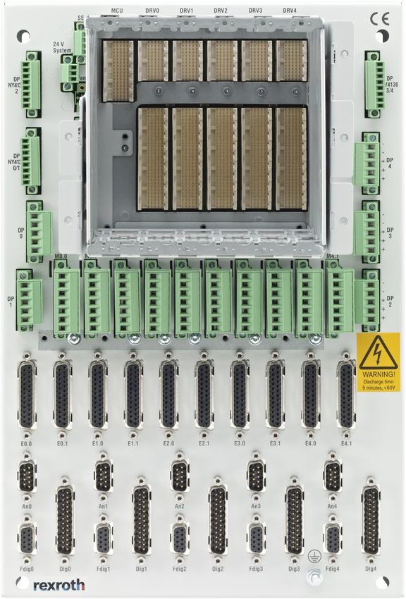
R911337318_Edition 09 Bosch Rexroth AG42/45 NYCe 4000 Multi-axis motion control Appendix – Declaration of Conformity system 18 Appendix – Declaration of Conformity Bosch Rexroth AG R911337318_Edition 09 Fig. 18-1: EU Declaration of conformity - page 1
NYCe 4000 Multi-axis motion control                                              43/45
system                                             Appendix – Declaration of Conformity

Fig. 18-2: EU Declaration of conformity - page 2
                                                    R911337318_Edition 09 Bosch Rexroth AG
44/45 NYCe 4000 Multi-axis motion control
system
Bosch Rexroth AG R911337318_Edition 09NYCe 4000 Multi-axis motion control 45/45 system Notes
Bosch Rexroth AG
   P.O. Box 13 57
   97803 Lohr a.Main, Germany
   Bgm.-Dr.-Nebel-Str. 2
   97816 Lohr a.Main, Germany
   Phone +49 9352 18 0
   Fax +49 9352 18 8400
   www.boschrexroth.com/electrics

*R911337318*
           R911337318

DOK-NY4000-SYST*40X3**-IT09-EN-P
You can also read