User and installation manual - QUADRO - Aqua Computer
←
→
Page content transcription
If your browser does not render page correctly, please read the page content below
aquacomputer                                                        QUADRO

         User and installation manual

                               QUADRO

                             aquasuite version 2018            ENGLISH: PAGE 1
                                                               DEUTSCH: SEITE 20
                           Current as of August 2018

All information contained in this manual is subject to change without prior notice.
                                 All rights reserved.

© 2018                    Aqua Computer GmbH & Co. KG                          -1-
                         Gelliehäuser Str. 1, 37130 Gleichen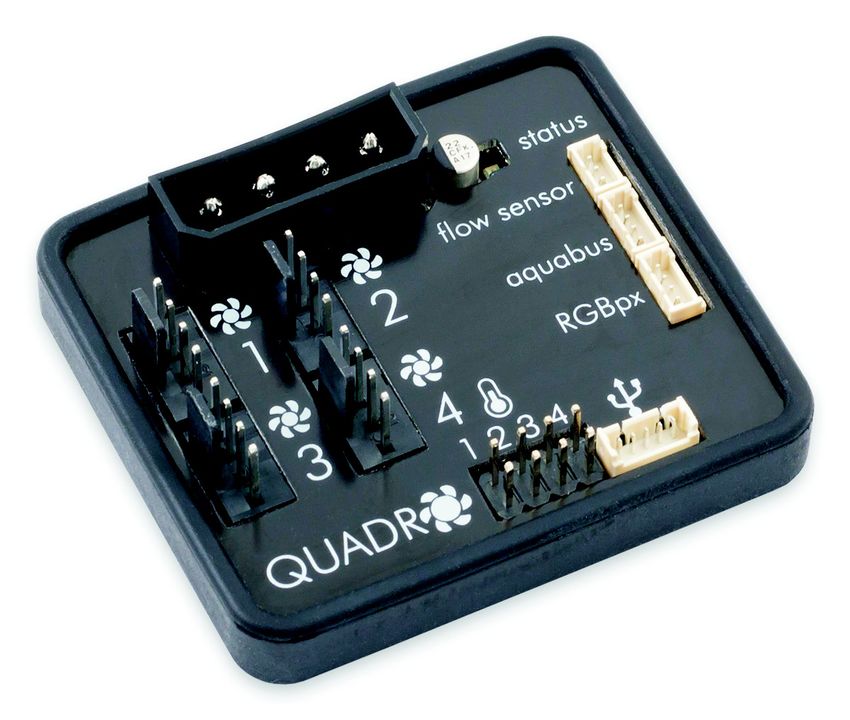
QUADRO                                                                    aquacomputer
Table of contents
1. Preface.........................................................................................3
2. Safety precautions.........................................................................3
3. Scope of delivery..........................................................................4
4. Assembly instructions.....................................................................4
5. Electrical connections....................................................................4
        5.1. QUADRO connector overview........................................................4
        5.2. Connector “Power supply”.............................................................4
        5.3. Connector “Fan 1/2/3/4”.............................................................5
        5.4. Connector “USB” .........................................................................5
        5.5. Connector “aquabus”...................................................................5
        5.6. Connector “flow sensor”................................................................6
        5.7. Connector for temperature sensors.................................................6
        5.8. Connector “RGBpx”......................................................................6
        5.9. Status LED....................................................................................6
6. aquasuite software........................................................................7
        6.1. Installation of the aquasuite software...............................................7
        6.2. Basic operation............................................................................7
        6.3. Symbols in the headlines................................................................7
7. Overview pages (aquasuite)...........................................................8
        7.1. Desktop mode..............................................................................8
        7.2. Creating new overview pages and activating edit mode....................8
        7.3. Adding new elements....................................................................9
        7.4. Editing existing elements................................................................9
        7.5. Values and names........................................................................9
        7.6. Detailed data elements..................................................................9
        7.7. Log data chart............................................................................10
        7.8. User defined: Images, text, drawing elements.................................10
        7.9. Export and import of overview pages.............................................10
8. Data quick view and data log (aquasuite).....................................11
        8.1. Log settings................................................................................11
        8.2. Analyze data..............................................................................11
        8.3. Manual data export.....................................................................12
        8.4. Automatic data export.................................................................12
9. Sensor configuration...................................................................13
        9.1. Hardware temperature sensor .....................................................13
        9.2. Hardware flow sensor..................................................................13
        9.3. Software sensors.........................................................................13
10. RGBpx configuration.................................................................14
        10.1. Strip settings.............................................................................14
        10.2. LED mapping...........................................................................14
-2-                              Aqua Computer GmbH & Co. KG                                      © 2018
                                Gelliehäuser Str. 1, 37130 Gleichen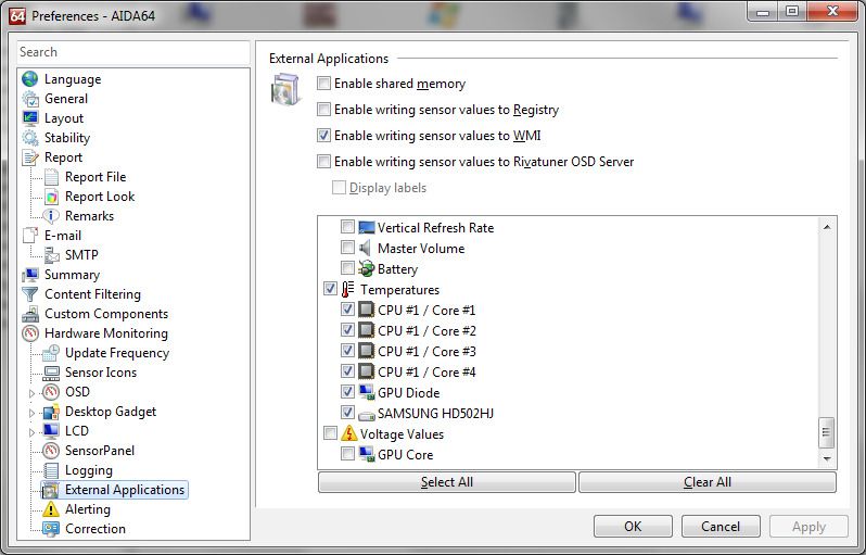
aquacomputer                                                                           QUADRO
       10.3. Sound controlled effects.............................................................15
       10.4. AMBIENTpx effect.....................................................................15
11. System settings QUADRO..........................................................15
       11.1. Device information....................................................................15
       11.2. Factory defaults........................................................................15
       11.3. aquabus configuration..............................................................15
       11.4. Firmware update.......................................................................16
12. aquasuite web..........................................................................16
       12.1. Data export..............................................................................16
       12.2. Data access.............................................................................16
       12.3. Data import..............................................................................17
13. Basic settings (aquasuite)...........................................................17
       13.1. Language................................................................................17
       13.2. Units.......................................................................................17
       13.3. Application start-up...................................................................17
       13.4. Service administration...............................................................17
       13.5. License manager.......................................................................18
14. Technical details and care instructions........................................18
       14.1. Technical details.......................................................................18
       14.2. Care instructions.......................................................................19
       14.3. Waste disposal.........................................................................19
       14.4. Contact Aqua Computer............................................................19

1. Preface
The QUADRO is a four channel PWM fan controller with outstanding functionality,
equally suited for water cooled or air cooled computers.
In addition to the four PWM fan outputs with speed signal monitoring, the
QUADRO is equipped with four temperature sensor inputs, one flow sensor input
as well as USB and aquabus interfaces. As a special feature, an integrated RGBpx
effect controller for up to 64 individually addressable LEDs is included.
Considering the fast technical development, we reserve the right to perform alter-
ations to the products at any time. It therefore is possible that your product does
not correspond precisely to the descriptions or especially the illustrations in this
manual.

2. Safety precautions
The following safety precautions have to be observed at all times:
   ●  Read this manual thoroughly and entirely!
   ●  Save your data onto suitable media before working on your hardware!
   ●  This product is not designed for use in life support appliances, devices, or
      systems where malfunction of this product can reasonably be expected to re-
© 2018                          Aqua Computer GmbH & Co. KG                                          -3-
                               Gelliehäuser Str. 1, 37130 Gleichen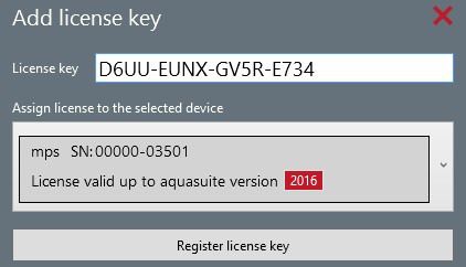
QUADRO aquacomputer
sult in personal injury. Aqua Computer GmbH & Co. KG customers using or
selling this product for use in such application do so at their own risk and
agree to fully indemnify Aqua Computer GmbH & Co. KG for any damages
resulting from such application!
3. Scope of delivery
● One QUADRO controller
● One temperature sensor (replacement part no. 53026)
● One internal USB cable (replacement part no. 53215)
● Four screws M3 x 8 mm (replacement part no. 91032 or 91069)
● Four hex nuts M3 (replacement part no. 91017)
● This manual
4. Assembly instructions
The QUADRO controller can be installed inside the PC case using the supplied
screws and nuts. In order to access the mounting holes, bend the rubber insulation
away from the top cover of the QUADRO controller and remove the top cover.
Reinstall the top cover afterwards.
Alternatively, double sided adhesive tape can be used to secure the QUADRO
controller inside the PC case.
Make sure that the electric connectors do not have contact to metal parts or other
electronic devices inside the PC case, otherwise malfunctions or destruction of the
QUADRO unit or other devices may occur!
5. Electrical connections
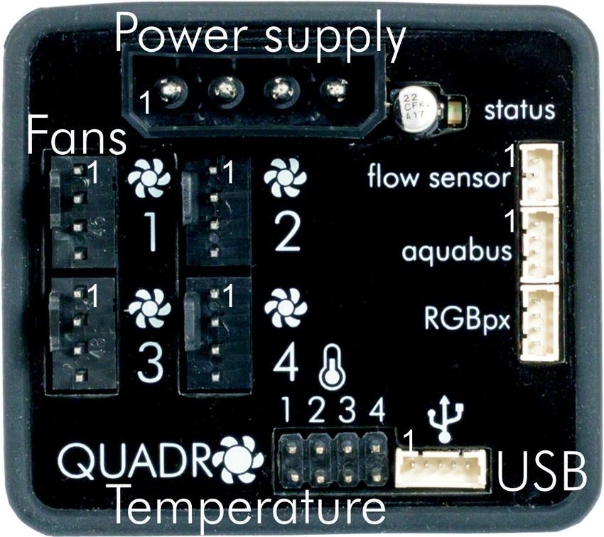
5.1. QUADRO connector overview
ATTENTION: Completely turn off your power supply or disconnect the mains pow-
er cord from the wall outlet before connecting or disconnecting any cables to/from
the device!
5.2. Connector “Power supply”
Please connect a HDD power plug of your PSU to this connector. Do not use ex-
cessive force but double check the polarity of the plug if you are having trouble to
connect.
Pin assignment: Pin 1 +12 V
Pin 2 GND
Pin 3 GND
Pin 4 +5 V
-4- Aqua Computer GmbH & Co. KG © 2018
Gelliehäuser Str. 1, 37130 Gleichen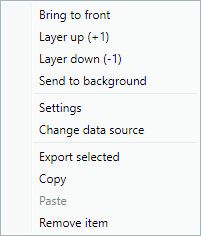
aquacomputer                                                   QUADRO
5.3. Connector “Fan 1/2/3/4”
PWM regulated fan outputs with speed signal processing.

Pin assignment:   Pin 1: GND
                  Pin 2: 12 V / max. 2 A
                  Pin 3: Speed signal
                  Pin 4: PWM signal

5.4. Connector “USB”
This connector is used for USB communication with a PC. Connect to an internal
USB header of your motherboard. Take special care to make sure the pin align-
ment matches your motherboard!
Pin assignment: Pin 1 not connected
                  Pin 2 GND (black)
                  Pin 3 D+ (green)
                  Pin 4 D-   (white)
                  Pin 5 +5 V (red)

5.5. Connector “aquabus”
Connector for communication with other Aqua Computer devices. USB and
aquabus interface can be used at the same time.
Pin assignment: Pin 1 GND
                  Pin 2 aquabus SDA
                  Pin 3 aquabus SCL
                  Pin 4 +5 V
Compatible aquabus devices:
   ●  aquaero 6 XT (53146, 53206, 53250, 53251, 53262, 53263)
   ●  aquaero 6 PRO (53145, 53253)
   ●  aquaero 6 LT (53234)

© 2018                    Aqua Computer GmbH & Co. KG                     -5-
                         Gelliehäuser Str. 1, 37130 Gleichen
QUADRO aquacomputer
● aquaero 5 XT (53089, 53125, 53249)
● aquaero 5 PRO (53090, 53252)
● aquaero 5 LT (53095)
5.6. Connector “flow sensor”
Flow sensor and special interconnecting cable are optional accessories and not in-
cluded in delivery.
Pin assignment: Pin 1 GND
Pin 2 flow sensor +5 V
Pin 3 flow sensor signal
Compatible flow sensors:
● Flow sensor with 5.6 mm nozzle (53061)
● Flow sensor “high flow” (53068)
● Connection cable flow sensor for VISION (53212)
5.7. Connector for temperature sensors
Connector for up to four temperature sensors.
Compatible sensors:
● Temperature sensor inline G1/4 (53066)
● Temperature sensor inner/outer thread G1/4 (53067)
● Temperature sensor G1/4 (53147)
● Temperature sensor plug&cool (53025)
● Temperature sensor 70 cm (53026)
5.8. Connector “RGBpx”
Compatible LED products and special interconnecting cables are optional acces-
sories and not included in delivery.
Compatible products:
● RGBpx LED-Strip (53268, 53269, 53270)
● RGBpx lighting set for PC cases (53271)
● RGBpx lighting set for monitors (53272)
● RGBpx Splitty4 (53267)
● RGBpx LED ring for aqualis 450/880 (53274)
● RGBpx cable (53259, 53260, 53261, 53266)
5.9. Status LED
The red status LED is continuously on during normal operation. The status LED is
blinking during error conditions, for example after fan output deactivation due to
overload or faulty supply voltage. In case of errors, RGBpx LEDs connected to the
device will be blinking in red, disregarding the current LED controller setup.
-6- Aqua Computer GmbH & Co. KG © 2018
Gelliehäuser Str. 1, 37130 Gleichenaquacomputer QUADRO
6. aquasuite software
The Windows software aquasuite is an extensive software suite and can be used
for configuration and monitoring. The software is not required for operation
though. All configuration parameters can be saved into the device's memory.
Please note: Depending on the type of product you are using, some features may
not be available for your device.
6.1. Installation of the aquasuite software
For configuration and monitoring of our products with USB interface, the aqua-
suite software is available for download from our website www.aqua-computer.de.
You will find the setup program in the support section of the website under Down-
loads/Software.
The setup program checks all connected USB devices for embedded software li-
censes and offers various aquasuite versions depending on detected devices. If no
device with a license for the latest aquasuite version is found, a warning is dis-
played and older aquasuite versions that do not require a license purchase can be
selected for installation. For installation and license validation, an internet connec-
tion is required.
The latest aquasuite version may also be installed if no valid license has been
found in a device. Subsequently, a license may be purchased or an existing license
key may be entered within the aquasuite. These functions can be accessed in the
aquasuite/License manager tab.
6.2. Basic operation
The program window is divided into two main areas. On the left side, a list of
“overview pages”, data quick view, data logger, device pages, aquasuite web and
aquasuite configuration is displayed, the right side shows the details of the current-
ly selected list element. The list can be hidden or restored by clicking the arrow
symbol in the upper left corner.
List elements may be minimized or maximized for easier access by clicking the title
bar. The title bars may contain various symbols that will be explained in the follow-
ing chapter.
6.3. Symbols in the headlines
Click the plus symbol in the “Overview pages” headline to create a new
overview page.
Clicking the monitor symbol will toggle desktop mode for this overview
page. While desktop mode is active, the color of the symbol will change
to orange.
© 2018 Aqua Computer GmbH & Co. KG -7-
Gelliehäuser Str. 1, 37130 GleichenQUADRO aquacomputer
Overview page: Clicking the padlock symbol will unlock or lock this over-
view page for editing. Device: Device can not be used due to license
problems, see license manager for details.
Clicking the gear symbol will access the basic configuration page of the
selected list element.
In order to save all settings into a device, click the disk symbol in the
headline.
This symbol indicates that communication with this device is not possible
at the moment. Check USB connection and power supply of the device if
necessary.
Clicking this symbol in the lower left corner of the aquasuite window will
display the news feed on aquasuite updates.
7. Overview pages (aquasuite)
Current sensor readings and diagrams from all supported devices can be dis-
played in overview pages. For each device a pre-configured overview page is au-
tomatically generated the first time the device is connected to the PC. These pages
can be individually modified and new pages can be created. Within one overview
page, data from all connected devices can be accessed.
7.1. Desktop mode
Each overview page can be displayed directly on your desktop. You can enable
desktop mode for an overview page by clicking the corresponding symbol in the
list of overview pages. Desktop mode can only be enabled for one overview page
at a time. With desktop mode enabled, elements of the overview page may cover
program symbols on your desktop, but mouse clicks are transmitted to underlying
desktop symbols.
If a overview page is unlocked for editing while desktop mode is active, the page
will be displayed in the aquasuite window for editing and the current desktop will
be displayed as background for your convenience.
7.2. Creating new overview pages and activating edit mode
In order to create a new overview page, click the plus symbol in the headline
“Overview pages”.
Existing overview pages can be unlocked for editing by clicking lock symbol in the
page listing.
-8- Aqua Computer GmbH & Co. KG © 2018
Gelliehäuser Str. 1, 37130 Gleichenaquacomputer QUADRO
7.3. Adding new elements
If the currently selected overview page is unlocked for editing, a plus symbol is dis-
played in the top right corner of the screen. Click the symbol to add a
new element to the page and select the desired element from the follow-
ing list. All available data is displayed in a tree diagram, click the arrow
symbols to access individual items.
Confirm your selection by clicking the check symbol in the bottom right corner.
The new element will be displayed in the upper left corner and the configuration
window is displayed. Configure the element as described in the next chapters.
7.4. Editing existing elements
If the currently selected overview page is unlocked for
editing, right-clicking an element will access a context
menu.
To access the settings of an element, select “Settings”
in the context menu or simply double click the element.
If you want to move an element, “drag” this element
while holding down the mouse button. Release the
mouse button when the element is at the desired posi-
tion.
7.5. Values and names
If the currently selected overview page is unlocked for editing, right-click an ele-
ment and select “Settings”. You may also double click the element.
Font face, size and color as well as position, decimal places and unit can be con-
figured for individual values.
7.6. Detailed data elements
If the currently selected overview page is unlocked for editing, right-click an ele-
ment and select “Settings”. You may also double click the element. Apart from po-
sition, size and color, the style of the element can be selected and configured. The
following styles are available:
● Headline only: Compact display as a headline.
● Text: Displays the numerical value in a box with a headline.
● Bar graph: Displays numerical value as well as bar graph.
● Chart: Displays the value in chronological sequence as a chart.
● Gauge: Displays the value as a analog gauge.
All display styles offer extensive configuration options, additionally statistical data
such as minimum, maximum and average can be displayed.
© 2018 Aqua Computer GmbH & Co. KG -9-
Gelliehäuser Str. 1, 37130 GleichenQUADRO aquacomputer
7.7. Log data chart
This element can be used to display charts on overview pages. The charts have to
be created using the data log functionality of the aquasuite before they become
available for overview pages. Please refer to the next chapter for details. Once a
chart has been configured, it can be selected from the “Chart selection” list on the
“Display” tab of the settings dialog.
7.8. User defined: Images, text, drawing elements
By using user defined controls, simple drawing elements such as circles, rectangles
and texts as well as images and more sophisticated elements can be added to an
overview page. To do so, add an “User defined” element to an overview page.
Switch to the “Display” tab in following dialog box, select the type of element to be
created from the drop down menu and confirm your selection by clicking the
“Load preset” button. Depending on the type of element, an additional dialog may
appear before the code (XAML, Extensible Application Markup Language) of the
new element is displayed in the lower part of the dialog window. You may want to
customize the code. By clocking the “Ok” Button, the new control is saved to the
overview page.
Step-by-step example to add an image: Select “Image” from the drop down menu
and click the “Load preset” button. Select an image file using the following file se-
lection dialog. The code is then displayed in the lower part of the dialog window
an can be modified. Save the new control by clicking the “Ok” button. The picture
will be displayed on the overview page.
More complex controls such as data bindings and animations are also available
but will require some programming experience for configuration.
7.9. Export and import of overview pages
Elements and complete overview pages can exported from the aquasuite and can
then be imported either on the same PC or on other PCs. For export as well as im-
port, the overview page must be in edit mode.
To export a complete page, right click a free spot of the page and select “Export
page” from the context menu. To export individual elements, select the element or
elements, perform a right click and select “Export selected” from the context menu.
For import, right click a free spot of the page and select “Import page” or “Import
items”from the context menu. Using “Import page”, the current page will be delet-
ed and only the imported page items will be displayed, using “Import items” will
add the items from file to the current page without altering the existing items. Dur-
ing import, the elements will be assigned to devices using the following scheme:
If a device with identical serial number is found on the computer, no changes are
made.
If no device with identical serial number is found on the computer, the element will
be assigned to the first device found of identical type.
- 10 - Aqua Computer GmbH & Co. KG © 2018
Gelliehäuser Str. 1, 37130 Gleichenaquacomputer QUADRO
When importing complex pages with elements referring to more than one device, it
is recommended to edit the device assignment in the file using a text editor prior to
importing.
8. Data quick view and data log (aquasuite)
All data currently monitored by the aquasuite can be accessed in the “Data quick
view” section. This includes data from connected USB devices as well as hardware
data supplied by the Aqua Computer background service. Displayed data may be
filtered using the text box next to the magnifier icon, a chart shows the develop-
ment over a maximum of ten minutes. All data shown here is not stored perma-
nently.
In contrast, the “Data log” may be used to selectively and permanently store data
from all connected Aqua Computer devices and hardware data supplied by the
background service. Logged data can then be analyzed by creating charts or be
exported to files. Data is only logged while the aquasuite software is being execut-
ed.
8.1. Log settings
The log settings can be accessed by clicking the “Log settings” element below the
“Data log” headline in the listing. To log data, create a new log data set by click-
ing the plus symbol in the upper right corner of the settings window. Enter name,
time interval and configure automatic deletion of old data to meet your require-
ments. You may then add the data sources to log by clicking the plus symbol in
the “Data sources” window section. You may add an unlimited number of data
sources to each log data set, the total number of log data sets is also unlimited.
8.2. Analyze data
Logged data can be visually evaluated as charts. To do so, select “Analyze data”
below the “Data log” headline in the listing. The chart will initially be empty, di-
rectly below the chart are eight buttons to modify the chart. In the lower section of
the window, the chart data can be configured.
To add data to the chart, first select the “Data sources” tab in the chart configura-
tion and select a data set to be displayed. If no data sources are available, you
will have to configure the log settings as described in the chapter “Log settings” of
this manual. Select the time period to be displayed on the right side of the window
and add the data to the chart by clicking the “Add data to chart” button. Repeat
this procedure if you want to display more than one data set in the chart.
You may modify the chart using the “Chart setup” and “Data series setup” tabs.
Finally, you can use the “Chart manager” tab to save the current chart configura-
tion and to load or delete previously saved configurations. All saved chart configu-
rations will be available on overview pages for the “Log data chart” element.
© 2018 Aqua Computer GmbH & Co. KG - 11 -
Gelliehäuser Str. 1, 37130 GleichenQUADRO aquacomputer
The currently displayed chart can be edited by using the buttons directly below the
chart and may also be saved as an image file. The button corresponding to the
currently selected function is highlighted by an orange frame. Please refer to the
following list for details on each function:
To save the currently displayed chart as an image file, click the floppy
disk symbol and select a name and location in the following dialog.
This function can be used to add horizontal lines to the chart. While this
function is activated, simply click into the chart to add a line at the current
cursor position.
This function can be used to add vertical lines to the chart. While this
function is activated, simply click into the chart to add a line at the current
cursor position.
This function can be used to add annotations to the chart. While this
function is activated, simply click into the chart to add an annotation at
the current cursor position. By clicking into the text box, you may edit the
text. You may also drag the little circle beside the text box to move the connecting
line to the desired position. Use drag and drop to move existing annotations.
This function can be used to remove horizontal/vertical lines or annota-
tions from the chart. While this function is activated, simply click the ele-
ment to be removed.
This function can be used to move the visible portion of the chart. Press
and hold the mouse button while moving the cursor in the chart to select
the position to be displayed, then release the button.
This function can be used to zoom in and out. Use the mouse wheel or
select the area to be displayed. You can reset the zoom settings by dou-
ble-clicking in the chart area.
This function will completely remove the chart.
8.3. Manual data export
Saved data can be exported from the data log into a XML file. To do so, select
“Analyze data” below the “Data log” headline in the listing. Select the “Data
sources” tab in the chart configuration and select a data set to be exported. If no
data sources are available, you will have to configure the log settings as described
in the chapter “Log settings” of this manual. Select the time period to be exported
on the right side of the window and start the export process by clicking the “Export
data” button. Enter a file name and path in the following dialog window.
8.4. Automatic data export
The automatic data export feature can be used to save data from the aquasuite
into an XML file on the hard disk or in the RAM (“memory mapped file”) in a regu-
- 12 - Aqua Computer GmbH & Co. KG © 2018
Gelliehäuser Str. 1, 37130 Gleichenaquacomputer QUADRO
lar time interval. The automatic data export will always overwrite the previously
saved data, so the file always contains only the most recent data set. Select “Auto-
matic data export” below the “Data log” headline in the listing to access the set-
tings screen. Create a new export data set by clicking the plus symbol in the upper
right corner of the screen. Enter name, path and time interval to meet your re-
quirements. You may then add the data sources to log by clicking the plus symbol
in the “Data sources” window section. You may add an unlimited number of data
sources to each export data set, the total number of export data sets is also unlim-
ited.
9. Sensor configuration
Select “Sensors” from the device list below the “QUADRO” entry. In the upper
area, the thirteen available sensors are displayed including current data. In the
lower area, the currently selected sensor can be configured.
9.1. Hardware temperature sensor
The first four sensors in the list represent the temperature sensor inputs of the
QUADRO.
If necessary, each temperature sensor can be calibrated by adding an offset of
±15 °C.
9.2. Hardware flow sensor
The fifth sensor in the list represents the flow sensor input of the QUADRO. Cali-
bration values for sensors sold by Aqua Computer can conveniently be selected
from a drop-down list. Select the appropriate entry for the flow sensor connected
to the QUADRO.
If necessary, the flow rate can be calibrated by ±10 %.
9.3. Software sensors
The last eight sensors in the list are software sensors and can be used to transmit
sensor data that is not physically available to the QUADRO controller from the
computer by USB connection.
During installation of the aquasuite, the background service “Aqua Computer Ser-
vice” is also installed. This service supplies various data from PC components, ad-
ditionally sensor data provided by third party software can be accessed. In order to
access third party software data, the third party software has to be correctly in-
stalled, configured and running.
Currently, the “Aqua Computer Service” supports data transfer from „HWiNFO“
(REALiX, Freeware, www.hwinfo.com) and „AIDA64“ (FinalWire Ltd., subject to li-
cense fees, www.aida64.com).
© 2018 Aqua Computer GmbH & Co. KG - 13 -
Gelliehäuser Str. 1, 37130 GleichenQUADRO aquacomputer
HWiNFO automatically exports all sensor values and does not need to be config-
ured. When using HWiNFO, the “Sensor Status” Window has to be open.
In the AIDA64 preferences menu, writing to WMI must be activated in the „external
applications“ sub-menu:
By clicking the plus symbol labeled “Data source”, one of the provided sensors
can be assigned to the selected software sensor.
For each software sensor, a scale factor and an offset may be configured for ma-
nipulation of the displayed sensor value. Data from third party software regularly
requires the scale factor to be adjusted.
10. RGBpx configuration
Select “RGBpx” from the device list below the “QUADRO” entry.
10.1. Strip settings
Configure basic settings for your RGBpx setup, most importantly the total number
of LEDs. While adjusting the total number of LEDs, the currently selected LEDs will
light up while the last LED is blinking for easy visual confirmation.
10.2. LED mapping
A total of four independent LED controllers can be configured to control sections
of the connected LEDs. After clicking the gear symbol next to the LED controller to
be configured, all available effects are displayed. Select the desired effect and
confirm by clicking the check symbol in the lower right corner.
- 14 - Aqua Computer GmbH & Co. KG © 2018
Gelliehäuser Str. 1, 37130 Gleichenaquacomputer QUADRO
Most effects offer extensive customization options such as color selection or speed
adjustment. Additionally, many effects can be configured to modify effect parame-
ters depending on current sensor data.
10.3. Sound controlled effects
Sound controlled effects can be used to visualize the current audio output of the
computer. A warning in the LED configuration area will notify you if the audio and
video features have been disabled in the aquasuite. In this case, please enable the
feature in the general aquasuite configuration. The general aquasuite configura-
tion can also be used to modify existing audio filters and define custom audio fil-
ters.
10.4. AMBIENTpx effect
The AMBIENTpx effect replicates the border area of the current monitor content on
the configured LEDs. This effect is meant to be used with LED strips installed to the
rear of the monitor for background lighting. A warning in the LED configuration
area will notify you if the audio and video features have been disabled in the
aquasuite. In this case, please enable the feature in the general aquasuite configu-
ration.
For each configured AMBIENTpx effect, please select the correct monitor, edge
and desktop range to evaluate for the effect.
The AMBIENTpx effect requires Windows version 8.1 or newer, screen content pre-
venting analysis by DRM or similar methods cannot be utilized for the effect.
11. System settings QUADRO
Select “System” from the device list below the “QUADRO” entry.
11.1. Device information
The details displayed here might be required when you contact our service for sup-
port.
11.2. Factory defaults
Click the button “Reset device to factory defaults” in the aquasuite or select the
“Factory defaults” entry from the menu for a complete reset of all settings. You will
have to completely reconfigure the device after resetting it to factory defaults!
11.3. aquabus configuration
Before connecting multiple QUADRO devices simultaneously to an aquaero 5/6
via aquabus, each device has to be configured to a unique aquabus address. If
only one device is connected via aquabus, this step may be skipped. Address 28
and 29 are available.
© 2018 Aqua Computer GmbH & Co. KG - 15 -
Gelliehäuser Str. 1, 37130 GleichenQUADRO aquacomputer
Changes to the bus address configuration are effective within a few seconds. How-
ever, it may take up to five minutes for a connected aquaero to update its configu-
ration.
11.4. Firmware update
The most up to date firmware for all supported devices is always included in the
current version of the aquasuite software. The button “ Update firmware now” will
start the update process for the device firmware.
During the firmware update process, do not disconnect the device from the PC
and do not power down the PC! After the firmware is successfully updated, the
aquasuite software will be automatically closed.
12. aquasuite web
Click the entry “aquasuite web” to publish data on the internet or import data from
the internet. The server for this service is operated by Aqua Computer and provid-
ed for use with the aquasuite, without warranty for for error free operation or per-
manent availability. Aqua Computer reserves the right to limit or cancel this service
at any time.
12.1. Data export
To publish data, create a new export data set by clicking the plus symbol in the
upper right corner of the “Data export” window. The name of the data set may be
modified to meet your requirements. You may then add the data sources to export
by clicking the plus symbol in the “Data sources” window section. By clicking the
gear symbol, the name of the corresponding value can be changed. Up to 30
data sources can be added to each export data set, the total number of export
data sets is limited to 10. All selected values will be transmitted to the Aqua Com-
puter server by the Aqua Computer background service approximately every 15
seconds, even after closing the aquasuite.
Notice regarding data security: All data contained in the configured export data
sets is transmitted to the Aqua Computer server with transport security. The server
stores the data set in volatile memory until a new data set is received or until 10
minutes have passed. Data received is not permanently stored, data is also not
correlated to IP addresses or other personal data. Data on the server may be ac-
cessed by anyone without restrictions, furthermore automatic data collection and
recording through third parties is possible. Use the data export feature for data
that you want to publish publicly and are allowed to do so only.
12.2. Data access
Published data can be obtained from the Aqua Computer server in various for-
mats. Generally, the “access key” is required to access data.
- 16 - Aqua Computer GmbH & Co. KG © 2018
Gelliehäuser Str. 1, 37130 Gleichenaquacomputer QUADRO
In addition to access through any internet browser and importing data into the
aquasuite, data is also available in JSON format and compatible to Circonus.
Furthermore, the server generates banner images in two different sizes from the
transmitted data, suitable to be included in forums signatures. The code required
for the Aqua Computer forums is provided for your convenience.
12.3. Data import
To import a data set from the Aqua Computer server, the “access key” of the data
set is required. The access key can be found in the aquasuite on the computer
providing the data in the “Data access” section.
Create a new import entry by clicking the plus symbol in the upper right corner of
the “Data import” window. Enter the access key of the data set to be imported. Up
to 10 data sets (each containing up to 30 values) can be configured.
In order to verify that data is being imported, use the “Data quick view” feature in
the aquasuite. Navigate to “Data from Aqua Computer service”, then “aquasuite
web”. For each imported data set, you should find an entry with the name of the
data set containing the individual values. It may take a few seconds before import-
ed data is displayed.
13. Basic settings (aquasuite)
Click the entry “Settings” below the headline “aquasuite” to access basic settings
for language, units and start-up of the software.
13.1. Language
Select a language from the drop down menu. After changing the language setting,
the software will have to be restarted.
13.2. Units
Select the units to be used for temperature and flow values from the drop down
menus. After changing these settings, the software will have to be restarted.
13.3. Application start-up
You may customize start-up behavior to suit your preferences. You may also select
to hide the task bar symbol of the software when minimized.
13.4. Service administration
The service (background service) configures special USB settings for all connected
Aqua Computer devices and should therefore always be active.
© 2018 Aqua Computer GmbH & Co. KG - 17 -
Gelliehäuser Str. 1, 37130 GleichenQUADRO aquacomputer
13.5. License manager
All aquasuite versions starting with annual version 2017 require a valid license. Li-
censes are generally assigned to individual devices, brand-new devices automati-
cally obtain a license for the current annual version and the following annual ver-
sion. For software activation, at least one device in the computer must contain a
corresponding license. If a valid license is detected for at least one device, all de-
vices connected to the computer can be used with this version. It is not mandatory
that each device has a corresponding license. For license validation, the aquasuite
requires an internet connection.
After successful license validation, a file containing current license data is stored
on the computer. A re-validation of the license is performed only if a new software
version (update) is installed or upon connection of new devices. New devices can
not be used prior to license re-validation, even if other devices with corresponding
licenses are connected at the same time.
To purchase a license, please use the “Buy license” button, which will open a web-
site with current prices and payment options.
If you have received a li-
cense key with a device or
bought one separately,
you may enter the key af-
ter clicking the “Add li-
cense” button. Select a
currently connected USB
device from the list for li-
cense assignment. After
clicking the “Register li-
cense key” button, the li-
cense is permanently assigned to the selected device and stored on the license
server. The key will not have to be re-entered after reinstallation of the software or
transfer of the device to another computer, but transferring the license to another
device is not possible.
During license validation and software activation, device serial numbers and a cal-
culated computer ID are transmitted to and stored on the license server. No further
personal information such as IP addresses are stored.
14. Technical details and care instructions
14.1. Technical details
Power supply: 12 V DC ±5 %, max. 8 A
5 V DC ±5 %, max. 3 A
- 18 - Aqua Computer GmbH & Co. KG © 2018
Gelliehäuser Str. 1, 37130 Gleichenaquacomputer QUADRO
Dimensions: 54 x 49 x 17 mm
Ambient temperature range: 10 to 40 °C (noncondensing)
14.2. Care instructions
Use a dry and soft cloth for cleaning. All electronic components and headers must
not get in contact with coolant or water!
14.3. Waste disposal
This device has to be disposed of as electronic waste. Please check
your local regulations for disposal of electronic waste.
14.4. Contact Aqua Computer
We are always happy to answer questions regarding our products and to receive
feedback. For answers on frequently asked questions, please also check our web-
site www.aqua-computer.de. You might also want to visit our forums and discuss
our products with experienced moderators and thousands of members – available
24/7. To get in direct contact with our customer support team, we offer several
options:
email: support@aqua-computer.de
Address: Aqua Computer GmbH & Co. KG
Gelliehäuser Str. 1
37130 Gleichen
Germany
Tel: +49 (0) 5508 9749290 (9-16 h CET, German and English language)
© 2018 Aqua Computer GmbH & Co. KG - 19 -
Gelliehäuser Str. 1, 37130 GleichenYou can also read