WAP-3101 CEILING MOUNT POE WIRELESS AP - USER'S MANUAL V1.0
←
→
Page content transcription
If your browser does not render page correctly, please read the page content below
WAP-3101
Ceiling Mount PoE Wireless AP

       User’s Manual

                                V1.0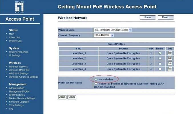
WAP-3101 Ceiling Mount PoE Wireless AP

Table of Contents

1      INTRODUCTION .................................................................................................................... 4
    1.1       FEATURES & BENEFITS ..................................................................................................... 4
    1.2       PACKAGE CONTENTS ........................................................................................................ 5
    1.3       ACCESS POINT DESCRIPTION ............................................................................................ 6
    1.4       SYSTEM REQUIREMENTS .................................................................................................. 6
    1.5       APPLICATIONS .................................................................................................................. 6
    1.6       NETWORK CONFIGURATION ............................................................................................... 7
2      UNDERSTANDING THE HARDWARE .................................................................................. 9
    2.1       HARDWARE INSTALLATION ................................................................................................. 9
    2.2       IP ADDRESS CONFIGURATION.......................................................................................... 10
3      WEB CONFIGURATION ...................................................................................................... 12
    3.1       LOGGING IN .................................................................................................................... 12
    3.2       STATUS .......................................................................................................................... 13
    3.2.1     MAIN – SYSTEM STATUS ................................................................................................. 13
    3.2.2     CLIENT LIST ................................................................................................................... 14
    3.2.3     SYSTEM LOG .................................................................................................................. 15
    3.3       SYSTEM ......................................................................................................................... 15
    3.3.1     SYSTEM PROPERTIES ..................................................................................................... 15
    3.3.2     IP SETTINGS .................................................................................................................. 16
    3.4       WIRELESS ...................................................................................................................... 16
    3.4.1     WIRELESS NETWORK ...................................................................................................... 17
    3.4.1.1      WIRELESS SECURITY - WEP....................................................................................... 18
    3.4.1.2      WIRELESS SECURITY – WPA-PSK, WPA2-PSK, WPA-MIXED .................................... 20
    3.4.1.3      WIRELESS SECURITY – WPA, WPA2 .......................................................................... 20
    3.4.2     WIRELESS MAC FILTER .................................................................................................. 21
    3.4.3     WDS LINK SETTINGS...................................................................................................... 22
    3.4.4     WIRELESS ADVANCED SETTINGS ..................................................................................... 24
    3.5       MANAGEMENT ................................................................................................................ 25
    3.5.1     ADMINISTRATION ............................................................................................................ 25
    3.5.2     MANAGEMENT VLAN ...................................................................................................... 26
    3.5.3     SNMP SETTINGS ........................................................................................................... 26
    3.5.4     BACKUP/RESTORE SETTINGS, RESET TO FACTORY DEFAULT SETTINGS .............................. 27
    3.5.5     FIRMWARE UPGRADE ...................................................................................................... 28
    3.5.6     TIME SETTINGS .............................................................................................................. 28
    3.5.7     LOG ............................................................................................................................... 29
APPENDIX A – SPECIFICATIONS ............................................................................................... 30
APPENDIX B – FCC INTERFERENCE STATEMENT ................................................................. 33
APPENDIX C – IC STATEMENT .................................................................................................. 34

                                                                                                                                                  2
WAP-3101 Ceiling Mount PoE Wireless AP

Revision History
 Version         Date                    Notes
 V1.0            20090122                Initial version

                                                           3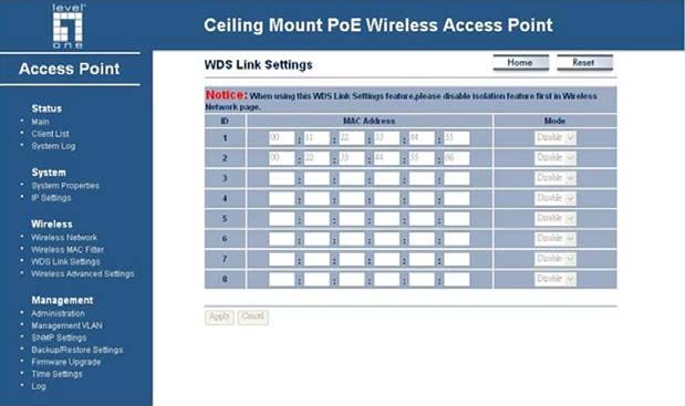
WAP-3101 Ceiling Mount PoE Wireless AP

   1 Introduction
   This is a smoke detector looking Wireless Access Point / Repeater / WDS that
   operates seamlessly in the 2.4 GHz frequency spectrum supporting the 802.11b
   (2.4GHz, 11Mbps) and faster 802.11g (2.4GHz, 54Mbps) wireless standards. It's the
   best way to add wireless capability to your existing wired network, or to add
   bandwidth to your wireless installation.

   This device features high transmitted output power and high receivable sensitivity
   along with antenna diversity. High output power and high sensitivity can extend
   range and coverage to reduce the roaming between Access Points to get more
   stable wireless connection. It also reduces the expense of equipment in the same
   environment.

   To protect your wireless connectivity, it can encrypt all wireless transmissions
   through 64/128-bit WEP data encryption and also supports WPA/WPA2. The MAC
   address filter lets you select exactly which stations should have access to your
   network. In addition, the User Isolation function can protect the private network
   between client users.

   The attractive design, high performance, and array of features makes this a suitable
   wireless solution for your residence or office.

   This chapter describes the features & benefits, package contents, applications, and
   network configuration.

   Features & Benefits
                   Features                                  Benefits
     High Speed Data Rate Up to 54Mbps      Capable of handling heavy data payloads
                                            such as MPEG video streaming
     High Output Power                      Extended excellent Range and Coverage
                                            (fewer APs)
     IEEE 802.11b/g Compliant               Fully Interoperable with IEEE
                                            802.11b/IEEE802.11g compliant devices
     Embedded Antenna                       Users won’t see antenna in your building
                                            environment
     WDS (Wireless Distributed System)      Make wireless AP and Bridge mode
                                            simultaneously as a wireless repeater
     Repeater                               The easiest way to expand your wireless
                                            network's coverage.
     Support Multi-SSID function (4 SSID)   Allow clients to access different networks
     in AP mode                             through a single access point and assign
                                            different policies and functions for each
                                            SSID by manager
     Diversity support                      Enhance the traffic signal

                                                                                         4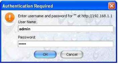
WAP-3101 Ceiling Mount PoE Wireless AP

     WPA2/WPA/ IEEE 802.1x support         Powerful data security
     MAC address filtering in AP mode(up   Ensures secure network connection
     to 50)
     User isolation support (AP mode)      Protect the private network between client
                                           users.
     Power-over-Ethernet (IEEE802.3af)     Flexible Access Point locations and cost
                                           savings
     Keep personal setting                 Keep the latest setting when firmware
                                           upgrade
     SNMP Remote Configuration             Help administrators to remotely configure
     Management                            or manage the Access Point easily.
     QoS (WMM) support                     Enhance user performance and density

   Package Contents

   Open the package carefully, and make sure that none of the items listed below are
   missing. Do not discard the packing materials, in case of return; the unit must be
   shipped in its original package.

         h    One Wireless Access Point Unit(WAP-3101)
         h    One Power Adapter (12V/ 1A)
         h    One CAT5 UTP Cable
         h    One Quick Installation Guide
         h    One CD-ROM with User’s Manual
         h    One mounting bracket
         h    Screw x2

                                                                                        5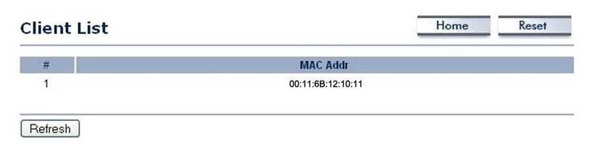
WAP-3101 Ceiling Mount PoE Wireless AP

   Access Point Description

                  Front Panel                                  Rear Panel

   System Requirements
       The following are the minimum system requirements in order configure the
       device.
       h PC/AT compatible computer with a Ethernet interface.
       h Operating system that supports HTTP web-browser

   Applications
   The wireless LAN products are easy to install and highly efficient. The following list
   describes some of the many applications made possible through the power and
   flexibility of wireless LANs:

           a) Difficult-to-wire environments
              There are many situations where wires cannot be laid easily. Historic
              buildings, older buildings, open areas and across busy streets make the
              installation of LANs either impossible or very expensive.
           b) Temporary workgroups
              Consider situations in parks, athletic arenas, exhibition centers, disaster-
              recovery, temporary offices and construction sites where one wants a
              temporary WLAN established and removed.
           c) The ability to access real-time information
              Doctors/nurses, point-of-sale employees, and warehouse workers can
              access real-time information while dealing with patients, serving
              customers and processing information.
           d) Frequently changed environments
              Show rooms, meeting rooms, retail stores, and manufacturing sites where
              frequently rearrange the workplace.
           e) Small Office and Home Office (SOHO) networks

                                                                                        6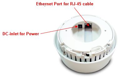
WAP-3101 Ceiling Mount PoE Wireless AP

              SOHO users need a cost-effective, easy and quick installation of a small
              network.
           f) Wireless extensions to Ethernet networks
              Network managers in dynamic environments can minimize the overhead
              caused by moves, extensions to networks, and other changes with
              wireless LANs.
           g) Wired LAN backup
              Network managers implement wireless LANs to provide backup for
              mission-critical applications running on wired networks.
           h) Training/Educational facilities
              Training sites at corporations and students at universities use wireless
              connectivity to ease access to information, information exchanges, and
              learning.

   Network Configuration
   To better understand how the wireless LAN products work together to create a
   wireless network, it might be helpful to depict a few of the possible wireless LAN PC
   card network configurations. The wireless LAN products can be configured as:

           a) Ad-hoc (or peer-to-peer) for departmental or SOHO LANs.
           b) Infrastructure for enterprise LANs.

           a) Ad-hoc (peer-to-peer) Mode

               This is the simplest network configuration with several computers
               equipped with the PC Cards that form a wireless network whenever they
               are within range of one another. In ad-hoc mode, each client is peer-to-
               peer, would only have access to the resources of the other client and
               does not require an access point. This is the easiest and least expensive
               way for the SOHO to set up a wireless network. The image below depicts
               a network in ad-hoc mode.

                                                                                       7
WAP-3101 Ceiling Mount PoE Wireless AP

           b) Infrastructure Mode

               The infrastructure mode requires the use of an access point (AP). In this
               mode, all wireless communication between two computers has to be via
               the AP. It doesn’t matter if the AP is stand-alone or wired to an Ethernet
               network. If used in stand-alone, the AP can extend the range of
               independent wireless LANs by acting as a repeater, which effectively
               doubles the distance between wireless stations. The image below
               depicts a network in infrastructure mode.

                                                                                       8
WAP-3101 Ceiling Mount PoE Wireless AP
Understanding the Hardware
Hardware Installation
1 Place the unit in an appropriate place after conducting a site survey.
2 Plug one end of the Ethernet cable into the RJ-45 port on the rear panel of the
device and another end into your PC/Notebook.
3 Insert the DC-inlet of the power adapter into the port labeled “DC-IN” and the
other end into the power socket on the wall.
This diagram depicts the hardware configuration
Ethernet
PC Access Point
AC/DC cable
Power Outlet
9WAP-3101 Ceiling Mount PoE Wireless AP
IP Address Configuration
The default IP address of the device is 192.168.1.1. In order to log into this device,
you must first configure the TCP/IP settings of your PC/Notebook.
1. In the control panel, double click Network Connections and then double click on
the connection of your Network Interface Card (NIC). You will then see the
following screen.
2. Select Internet Protocol (TCP/IP) and then click on the Properties button. This
will allow you to configure the TCP/IP settings of your PC/Notebook.
10WAP-3101 Ceiling Mount PoE Wireless AP
3. Select Use the following IP Address radio button and then enter the IP address
and subnet mask. Ensure that the IP address and subnet mask are on the same
subnet as the device.
For Example: Device IP address: 192.168.1.1
PC IP address: 192.168.1.10
PC subnet mask: 255.255.255.0
4. Click on the OK button to close this window, and once again to close LAN
properties window.
11WAP-3101 Ceiling Mount PoE Wireless AP
Web Configuration
Logging In
To configure the device through the web-browser, enter the IP address of the Bridge
(default: 192.168.1.1) into the address bar of the web-browser and press Enter.
Make sure that the Bridge and your computers are on the same subnet. Refer to
Chapter 2 in order to configure the IP address of your computer.
Username:admin; Password:admin
After logging in you will see the graphical user
interface (GUI) of the device. The navigation
drop-down menu on left is divided into four main
sections:
1. Status: This includes the main status page,
DHCP client list, and system log.
2. System: This includes the system properties
and IP settings.
3. Wireless: This includes the basic, advanced,
security, WDS, and MAC filter for the wireless
interface.
4. Management: This includes the administrator
password settings, VLAN and SNMP settings,
backup/restore configuration, firmware upgrade,
time settings, and the system log.
The status page is also displayed once you have
logged in. This includes details about the system,
wireless, and TCP/IP configuration.
12WAP-3101 Ceiling Mount PoE Wireless AP
Status
Click on the Status link on the navigation drop-
down menu. You will then see three options:
main, client list, and system log. Each option is
described below.
Main – System Status
The Main page is the first page that is displayed once you have logged in. The
following information is included on this page:
o System Information – device name, Ethernet MAC address, Wireless MAC
address, country, current time, firmware version, and VLAN management tag.
o Current IP Settings: IP address, subnet mask, default gateway, and DHCP
client status.
o Current Wireless Settings: Operation mode, wireless mode, channel
frequency, profile isolation, profile settings such as SSID, and security
settings.
13WAP-3101 Ceiling Mount PoE Wireless AP
Client List
Click on the Client List link to view a list of devices that are associated with the
Access Point.
Click on the Refresh button to view an updated list of devices that are associated
with the Access Point.
14WAP-3101 Ceiling Mount PoE Wireless AP
System Log
The System Log page displays a list of events that are triggered on the Ethernet
and Wireless interface. This log can be referred to when an unknown error occurs on
the system or when a report needs to be sent to the technical support department for
debugging purposes.
System
Click on the System link on the navigation
drop-down menu. You will then see two
options: system properties and IP settings.
Each option is described below.
System Properties
The System Properties allows you to configure a name for the device (this is not
the SSID), select and country and the operational mode.
Device Name: Specify a name for the device – this is not the SSID.
Country/Region: Select the region from the drop-down list.
15WAP-3101 Ceiling Mount PoE Wireless AP
Operation Mode: Select Access Point or Repeater radio button. In order to
configure the Repeater, click on the WDS Link Settings under the Wireless drop-
down menu.
Click on the Apply button to save the changes.
IP Settings
The IP Settings page allows you to configure the device with a static IP address
or a DHCP client.
IP Network Setting: Select Obtain an IP address automatically (DHCP) radio
button if the Access Point is connected to a DHCP server. This will allow the Access
Point to pass IP addresses to the clients associated with it. You may select Specify
an IP Address radio button if you would like the device to use a static IP address. In
this case, you would be required to specify an IP address, subnet mask, and default
gateway IP address.
IP Address: Specify an IP address
IP Subnet Mask: Specify the subnet mask for the IP address
Default Gateway: Specify the IP address of the default gateway.
Click on the Apply button to save the changes.
Wireless
Click on the Wireless link on the
navigation drop-down menu. You will then
see four options: wireless network,
wireless MAC filter, WDS link settings, and
wireless advanced settings. Each option is
described below.
16WAP-3101 Ceiling Mount PoE Wireless AP
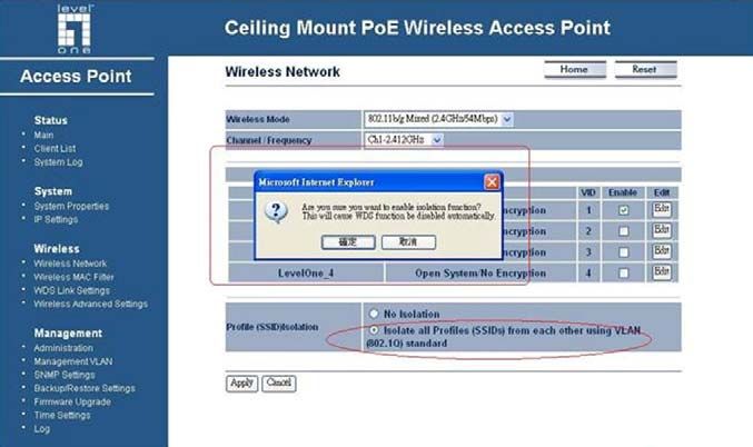
Wireless Network
The Wireless Network page allows you to configure the wireless mode, channel,
SSID, and security settings.
Wireless Mode: Depending on the type of wireless clients that are connected to the
network, you may select B, G, or B/G-mixed. If you are not sure about which clients
will be accessing the wireless networks, it is recommended that you select B/G-
mixed for the best performance.
Channel: Select a channel from the drop-down list. The channels available are
based on the country’s regulation. When selecting Infrastructure mode, a channel is
not required, however, when selecting Adhoc mode, you must select the same
channel on all points.
Channel: You may configure up to four different wireless profiles. Click on the Edit
button to modify the profile and place a check in the Enable box to activate the
profile.
17WAP-3101 Ceiling Mount PoE Wireless AP
SSID: The SSID is a unique named shared amongst all the points of the wireless
network. The SSID must be identical on all points of the wireless network and cannot
exceed 32 characters.
VLAN ID: If you have enabled VLAN tagging on your network, specify the VLAN tag
ID.
Suppressed SSID: Place a check in this box if you would like to hide the SSID. By
enabling this feature, wireless clients will not be able to scan this access point in a
site survey.
Station Separator: This is also known as layer 2 isolation. Clients connected to this
Access Point will not be able to directly communicate with each other.
Security Mode: By default, the security is disabled. Refer to the next section to
configure the security features such as WEP, WPA, WPA-PSK, WPA2, WPA2-PSK
and WPA-Mixed
Click on the Apply button to save the changes.
Wireless Security - WEP
Security Mode: Select WEP from the drop-down list if your wireless network uses
WEP encryption. WEP is an acronym for Wired Equivalent Privacy, and is a security
protocol that provides the same level of security for wireless networks as for a wired
network.
18WAP-3101 Ceiling Mount PoE Wireless AP
Authentication Type: Select an authentication method. Options available are Open
Key, Shared Key or Auto (Auto:AP mode only). An open system allows any client
to authenticate as long as it conforms to any MAC address filter policies that may
have been set. All authentication packets are transmitted without encryption. Shared
Key sends an unencrypted challenge text string to any device attempting to
communicate with the Access Point. The device requesting authentication encrypts
the challenge text and sends it back to the Access Point. If the challenge text is
encrypted correctly, the Access Point allows the requesting device to authenticate. It
is recommended to select Auto if you are not sure which authentication type is used.
Input Type: Select He or ASCII from the drop-down list
Key Length: Select a key format from the drop-down list. 64bit-hex keys require 10
characters, where as 128-bit keys require 26 characters. 128bit keys require 32
characters. A hex key is defined as a number between 0 through 9 and letter
between A through F.
Default Key: You may use up to four different keys for four different networks. Select
the current key that will be used.
Key 1-4: You may enter four different WEP keys.
Click on the Apply button to save the changes.
19WAP-3101 Ceiling Mount PoE Wireless AP
Wireless Security – WPA-PSK, WPA2-PSK, WPA-Mixed
Security Mode: Select WPA-PSK, WPA2-PSK, or WPA-Mixed from the drop-down
list if your wireless network uses WPA pre-shared key. (WPA, WPA2 and WPA-
Mixed:AP mode only)
Encryption: Select TKIP or AES from the drop-down list if your wireless network
uses this encryption. WPA (Wi-Fi Protected Access) was designed to improve upon
the security features of WEP (Wired Equivalent Privacy). The technology is designed
to work with existing Wi-Fi products that have been enabled with WEP. WPA
provides improved data encryption through the Temporal Integrity Protocol (TKIP),
which scrambles the keys using a hashing algorithm and by adding an integrity
checking feature which makes sure that keys haven’t been tampered with.
Passphrase: Specify a passphrase that is shared amongst the Access Points and
clients.
Group Key Update Interval: Specify the number of seconds after which the Access
Point will probe the client for the passphrase.
Click on the Apply button to save the changes.
Wireless Security – WPA, WPA2 (AP mode only)
Security Mode: Select WPA or WPA2 from the drop-down list if your wireless
network uses WPA. WPA (Wi-Fi Protected Access) was designed to improve upon
the security features of WEP (Wired Equivalent Privacy). The technology is designed
to work with existing Wi-Fi products that have been enabled with WEP. WPA
provides improved data encryption through the Temporal Integrity Protocol (TKIP),
which scrambles the keys using a hashing algorithm and by adding an integrity
checking feature which makes sure that keys haven’t been tampered with.
20WAP-3101 Ceiling Mount PoE Wireless AP
Encryption: Select TKIP or AES from the drop-down list if your wireless network
uses this encryption.
RADIUS IP Address: Enter the IP address of the RADIUS server.
RADIUS Port: Enter the port number of the RADIUS server. The default is usually
1812.
RADIUS Secret: Enter the shared password of the RADIUS server.
Group Key Update Interval: Specify the number of seconds after which the Access
Point will probe the client for the secret.
Click on the Apply button to save the changes.
Wireless MAC Filter
Click on the Wireless MAC Filter link under the Wireless menu. On this page you
can filter the MAC address by allowing or blocking access the network.
ACL (Access Control) Mode: You may choose to Disable, Allow Listed, or Deny
Listed MAC addresses from associating with the network. By selecting Allow MAC
in the List, only the address listed in the table will have access to the network; all
21WAP-3101 Ceiling Mount PoE Wireless AP
other clients will be blocked. On the other hand, selected Deny MAC in the List,
only the listed MAC addresses will be blocked from accessing the network; all other
clients will have access to the network.
MAC Address: Enter the MAC address.
This table lists the blocked or allowed MAC addresses; you may delete selected
MAC address or delete all the addresses from the table by clicking on the Delete
button.
Click on the Apply button to save the changes.
WDS Link Settings
Click on the WDS Link Settings On this page you can configure the WDS (Wireless
Distribution System) which allows the Access Point to function as a repeater.
WDS MAC Address: Specify the MAC address of the Access Points that will join the
WDS network and then select Enable or Disable from the drop-down list.
Click on the Apply button to save the changes.
22WAP-3101 Ceiling Mount PoE Wireless AP
WDS:Enable, VLAN:Disable
VLAN:Disable
23WAP-3101 Ceiling Mount PoE Wireless AP
Wireless Advanced Settings
Click on the Wireless Advanced Settings link. On this page you can configure the
advanced settings to tweak the performance of your wireless network. Options
available are: data rate, transmit power, antenna diversity, fragmentation threshold,
RTS threshold, and 802.11g protection.
Data Rate: If you would like to force a data rate, you may select one from the drop-
down list. However, for best performance it is recommended to use the Auto setting.
Transmit Power: You may have the different application distance of the device by
selecting a value from the drop-down list. This feature can be helpful in restricting the
coverage area of the wireless network.
You can arrange the different data rate in distance in Access Point mode. Please
refer below table. The table only for 11g and 11b/g mix mode
6M-24M 36M 48M 54M
High ˇ ˇ ˇ Great
Ultra High ˇ ˇ Great N/A
Super ˇ Great NA N/A
Extreme Great N/A N/A N/A
Fragment: Packets over the specified size will be fragmented in order to improve
performance on noisy networks.
RTS Threshold: Packets over the specified size will use the RTS/CTS mechanism to
maintain performance in noisy networks and preventing hidden nodes from
degrading the performance.
Protection Mode: If your wireless network is using both 802.11b and 802.g devices
then it is recommended to enable this feature so that the 802.11b devices will not
degrade the performance of 802.11g devices.
Click on the Apply button to save the changes.
24WAP-3101 Ceiling Mount PoE Wireless AP
Management
Click on the Management link on the
navigation drop-down menu. You will then
see seven options: administration,
management VLAN, SNMP settings,
backup/restore settings, firmware upgrade,
time settings, and log. Each option is
described below.
Administration
Click on the Administration link under the Management menu. This option allows
you to create a user name and password for the device. By default, this device is
configured without a user name and password Admin. For security reasons it is
highly recommended that you create a new user name and password.
Name: Specify a user name into the first field.
Password: Specify a password into this field and then re-type the password into the
Confirm Password field. Then click on the Apply button.
Click on the Apply button to save the changes.
25WAP-3101 Ceiling Mount PoE Wireless AP
Management VLAN
Click on the SNMP link under the Management menu. This option allows you to
assign a VLAN tag to the packets. A VLAN is a group of computers on a network
whose software has been configured so that they behave as if they were on a
separate Local Area Network (LAN). Computers on VLAN do not have to be
physically located next to one another on the LAN
Management VLAN ID: If your network includes VLANs and if tagged packets need
to pass through the Access Point, specify the VLAN ID into this field. If not, select the
No VLAN tag radio button.
Note: If your reconfigure the Management VLAN ID, you may lose connectivity to the
Access Point. Verify that the switch and DHCP server can support the reconfigured
VLAN ID, and then re-connect to the new IP address.
Click on the Apply button to save the changes.
SNMP Settings
Click on the SNMP Settings link under the Management menu. This option allows
you to assign the contact details, location, community name and trap settings for
SNMP This is a networking management protocol used to monitor network-attached
devices. SNMP allows messages (called protocol data units) to be sent to various
parts of a network. Upon receiving these messages, SNMP-compatible devices
(called agents) return data stored in their Management Information Bases. .
26WAP-3101 Ceiling Mount PoE Wireless AP
SNMP Enable/Disable: Choose to enable or disable the SNMP feature.
Contact: Specify the contact details of the device.
Location: Specify the location of the device.
Read-Only Community Name: Specify the password for access the SNMP
community for read only access.
Read-Write Community Name: Specify the password for access to the SNMP
community with read/write access.
Send SNMP Trap: Specify the IP address of the computer that will receive the
SNMP traps.
Trap Community Name: Specify the password for the SNMP trap community.
Click on the Apply button to save the changes.
Backup/Restore settings, Reset to factory default settings
Click on the Backup/Restore Setting link under the Management menu. This option
is used to save the current settings of the device in a file on your local disk or load
settings on to the device from a local disk. This feature is very handy for
administrators who have several devices that need to be configured with the same
settings.
Save a copy of the current settings: Click on the Backup button to save the current
configuration.
Restore saved settings from a file: Once a file has been backed up, you may
restore it by clicking on the Browse button to select the file, and then the Restore
button.
Revert to factory default settings: Click on the Factory Default Settings button to
reset the device to the default settings. Please wait while the device restart and then
access the device using the default IP address: 192.168.1.1
27WAP-3101 Ceiling Mount PoE Wireless AP
Firmware Upgrade
Click on the Upgrade Firmware link under the Management menu. This page is
used to upgrade the firmware on the device. Make sure that downloaded the
appropriate firmware from your vendor.
Click on the Browse button and then select the appropriate firmware and then click
on the Upgrade button.
Note: The upgrade process may take about 1 minute to complete. Do not power off
the device during this process as it may crash the device and make it unusable. The
device will restart automatically once the upgrade is complete.
Time Settings
Click on the Time Settings link under the Management menu. This page allows you
to configure the time on the device. You may do this manually or by connecting to a
NTP server.
Manually Set Date and Time: Specify the date and time
Automatically Get Date and Time: Select the time zone from the drop down list and
then specify the IP address of the NTP server.
Click on the Apply button to save the changes.
28WAP-3101 Ceiling Mount PoE Wireless AP
Log
Click on the Log link under the Management menu. The Log page displays a list of
events that are triggered on the Ethernet and Wireless interface. This log can be
referred when an unknown error occurs on the system or when a report needs to be
sent to the technical support department for debugging purposes.
Syslog: Choose to enable or disable the system log.
Log Server IP Address: Specify the IP address of the server that will receive the
system log.
Local Log: Choose to enable or disable the local log.
Click on the Apply button to save the changes.
29WAP-3101 Ceiling Mount PoE Wireless AP
Appendix A – Specifications
Hardware
Physical Interface z LAN: One 10/100 Fast Ethernet RJ-45
z Reset Button
z Power Jack
LEDs Status z Power/ Status
z LAN (10/100Mbps)
z WLAN (Wireless Connection)
Power Requirements z Power Supply: 90 to 240 VDC ± 10%, 50/60 Hz (depends on
different countries)
z Active Ethernet (Power over Ethernet, IEEE802.3af)- 48
VDC/0.375A
z Device: 12V/1A
Regulation Certifications z FCC Part 15/UL, ETSI 300/328/CE
RF Specification
Frequency Band 2.400~2.484 GHz
Media Access Protocol Carrier sense multiple access with collision avoidance (CSMA/CA)
Modulation Technology z OFDM: BPSK, QPSK, 16-QAM, 64-QAM
z DBPSK, DQPSK, CCK
Operating Channels 11 for North America, 14 for Japan, 13 for Europe
Receive Sensitivity z IEEE802.11g
(Typical) 6Mbps@ -95dBm
54Mbps@ -75dBm
z IEEE802.11b
1Mbps@ -98dBm
11Mbps@ -93dBm
Available transmit power z IEEE802.11g
26dBm@6~24 Mbps
25dBm@36 Mbps
23dBm@48 Mbps
22dBm@54Mbps
z IEEE802.11b
27dBm@1 ~ 11Mbps
3011g Wireless Multi-Client Bridge/AP/WDS Version 1.0
Antenna Directional Embedded antenna
Peak Gain = 6 dBi
Software Features
Topology Infrastructure/Ad-Hoc
Operation Mode Access Point/Repeater/WDS
LAN • DHCP Client
VPN VPN pass-through (PPTP, L2TP, IPSEC)
Wireless • Wireless Mode – 11b / 11g / Disable
• Channel Selection (Setting varies by Country)
• Transmission Rate
¾ 11 b/g: 54, 48, 36, 24, 18, 12, 11, 9, 6, 5.5, 2, 1 in Mbps
• Transmit power (4 levels)
• Antenna Diversity
• Super G(AP mode only)
Security • WEP Encryption-64/128/152 bit
• WPA Personal (WPA-PSK using TKIP or AES)
• WPA Enterprise (WPA-EAP using TKIP)
• 802.1x Authenticator
• Hide SSID in beacons
• Multiple SSID with 802.1q VLAN tagging (up to 4 SSIDs)
• MAC Filter
• L2 isolation
• Wireless STA (Client) connected list
QoS • WMM
Management
Configuration Web-based configuration (HTTP)/Telnet
Firmware Upgrade • Upgrade firmware via web-browser
• Keep latest setting when f/w update
Administrator Setting Administrator password change
Reset Setting • Reboot
• Reset to Factory Default
System monitoring Status, Statistics and Event Log
SNMP V1, V2c
3111g Wireless Multi-Client Bridge/AP/WDS Version 1.0
MIB MIB I, MIB II (RFC1213) and Private MIB
Bandwidth Measurement Port / IP
Backup & Restore Settings through Web
Environment & Physical
Temperature Range • Operating: 0°C to 45°C (32°F to 113°F)
• Storage: -20°C to 70°C (-4°F to 158°F)
Humidity (non-condensing) 5%~95% typical
Dimensions Diameter:120mm
Height: 50mm
Weight 280g
3211g Wireless Multi-Client Bridge/AP/WDS Version 1.0
Appendix B – FCC Interference Statement
Federal Communication Commission Interference Statement
This equipment has been tested and found to comply with the limits for a Class B digital device,
pursuant to Part 15 of the FCC Rules. These limits are designed to provide reasonable protection
against harmful interference in a residential installation. This equipment generates uses and can
radiate radio frequency energy and, if not installed and used in accordance with the instructions, may
cause harmful interference to radio communications. However, there is no guarantee that interference
will not occur in a particular installation. If this equipment does cause harmful interference to radio or
television reception, which can be determined by turning the equipment off and on, the user is
encouraged to try to correct the interference by one of the following measures:
z Reorient or relocate the receiving antenna.
z Increase the separation between the equipment and receiver.
z Connect the equipment into an outlet on a circuit different from that to which the receiver is
connected.
z Consult the dealer or an experienced radio/TV technician for help.
FCC Caution: Any changes or modifications not expressly approved by the party responsible for
compliance could void the user's authority to operate this equipment.
This device complies with Part 15 of the FCC Rules. Operation is subject to the following two conditions:
(1) This device may not cause harmful interference, and (2) this device must accept any interference
received, including interference that may cause undesired operation.
IMPORTANT NOTE:
FCC Radiation Exposure Statement:
This equipment complies with FCC radiation exposure limits set forth for an uncontrolled environment.
This device complies with FCC RF Exposure limits set forth for an uncontrolled environment, under 47
CFR 2.1093 paragraph (d)(2).
This transmitter must not be co-located or operating in conjunction with any other antenna or transmitter.
3311g Wireless Multi-Client Bridge/AP/WDS Version 1.0
Appendix C – IC Statement
IC statement
Operation is subject to the following two conditions:
This device may not cause interference and
This device must accept any interference, including interference that may cause undesired operation of
the device.
This device has been designed to operate with an antenna having a maximum gain of 9 dBi. Antenna
having a higher gain is strictly prohibited per regulations of Industry Canada. The required antenna
impedance is 50 ohms.
IMPORTANT NOTE:
IC Radiation Exposure Statement:
This equipment complies with IC radiation exposure limits set forth for an uncontrolled environment.
End users must follow the specific operating instructions for satisfying RF exposure compliance. This
equipment should be installed and operated with minimum distance 20cm between the radiator & your
body.
This transmitter must not be co-located or operating in conjunction with any other antenna or transmitter.
Règlement d’Industry Canada
Les conditions de fonctionnement sont sujettes à deux conditions:
Ce périphérique ne doit pas causer d’interférence et.
Ce périphérique doit accepter toute interférence, y compris les interférences pouvant perturber le bon
fonctionnement de ce périphérique.
34You can also read