I20-T Door Phone
     User Manual
←
→
Page content transcription
If your browser does not render page correctly, please read the page content below

I20-T Door Phone
User Manual
Safety Notices

1. Please use the specified power adapter. If special circumstances need to use the power adapter
provided by other manufacturers,please make sure the voltage and current provided in accordance
with the requirements of this product, meanwhile, please use the safety certificated products,
otherwise may cause fire or get an electric shock.When using this product, please do not damage
the power cord,or forcefully twist it、Stretch pull or banding, and not to be under heavy pressure or
between items, Otherwise may cause the power cord damage, thus lead to fire or get an electric
shock.

2. Before use, please confirm the temperature and environment humidity suitable for the product
work.(Move the product from air conditioning room to natural temperature, which may cause this
product surface or internal components produce condense water vapor, please open power use it
after waiting for this product is natural drying.)
3.Non-technical staff not remove or repair, improper repair or may cause electric shock, fire or
malfunction, etc,Which can lead to injury accident, and also can cause your product damage.
4. Do not use fingers, pins, wire and other metal objects, foreign body into the vents and gaps. It
may cause current through the metal or foreign body,which even cause cause electric shock and
injury accident. If any foreign body or objection fall into the product please stop usage.
5. Please do not discard the packing bags or stored in places where children could reach,if children
trap his head with it,may cause nose and mouth blocked,and even lead to suffocation.
6. Please use this product with normal usage and operating,in bad posture for a long time to use
this product may affect your health.
7. Please read the above safety notices before installing or using this phone. They are crucial for
the safe and reliable operation of the device.

                                                                                                   2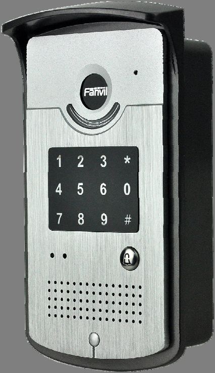
Table of Content
1. Acquaint I20-T.................................................... 4
   1.1. I20-T Front............................................................................................................................................................... 4
   1.2. Key Description ....................................................................................................................................................... 5
2. Start Using ....................................................... 5
   2.1. Connect the power supply and the network .................................................................................................. 5
        2.1.1. Connect Network ....................................................................................................................................... 5
   2.2. Quick Setting.......................................................................................................................................................... 9
3. I20-T Door Phone Basic Operation ................................ 10
   3.1. Answering a Call ................................................................................................................................................. 10
   3.3. End a Call .............................................................................................................................................................. 10
   3.5. Door Open Operation ......................................................................................................................................... 11
4. Page Configuration .............................................. 11
   4.1. Ways to configure ............................................................................................................................................... 11
        4.1.1.Ways to configure ..................................................................................................................................... 11
        4.1.2. Password Configuration ........................................................................................................................ 11
   4.2. Setting via web browser.................................................................................................................................... 11
   4.3. WEB Page Functional Explanation ................................................................................................................ 12
        4.3.1. BASIC.......................................................................................................................................................... 12
             4.3.1.1. Status .............................................................................................................................................. 12
             4.3.1.2. Wizard.............................................................................................................................................. 12
             4.3.1.3. Call Log ........................................................................................................................................... 15
        4.3.2. Network ...................................................................................................................................................... 16
             4.3.2.1. WAN Config ................................................................................................................................... 16
             4.3.2.2. Qos Config ..................................................................................................................................... 18
             4.3.2.3. Service Port ................................................................................................................................... 20
             4.3.2.4. TIME&DATE ................................................................................................................................... 21
        4.3.3. VOIP ............................................................................................................................................................ 22
             4.3.3.1. SIP Config....................................................................................................................................... 22
             4.3.3.2. Stun Config .................................................................................................................................... 28
        4.3.5.    FUNCTION KEY ................................................................................................................................... 29
             4.3.5.1. Function key ............................................................................................................................... 29
             4.3.5.2. Door Card Setting ...................................................................................................................... 32
             4.3.5.3. Call Log ........................................................................................................................................ 33
5. Appendix ....................................................... 33
       5.1.1.Specifications: ........................................................................................................................................... 34
       5.1.2. Basic Feature ............................................................................................................................................ 34
       5.1.3. Schematic Diagram ................................................................................................................................... 35
   5.2、Owner Remote Opens the Voice Access Controller by VOIP Phone ................................................... 35
   5.3、Card Management ............................................................................................................................................. 35
          5.3.1 Issue Card Management ........................................................................................................................... 35
          5.3.2Issue User Card ........................................................................................................................................... 36
          5.3.3 Delete the user card (Method 1): .............................................................................................................. 37
          5.3.4、Add Remote Visit Data .......................................................................................................................... 38

                                                                                                                                                                                  3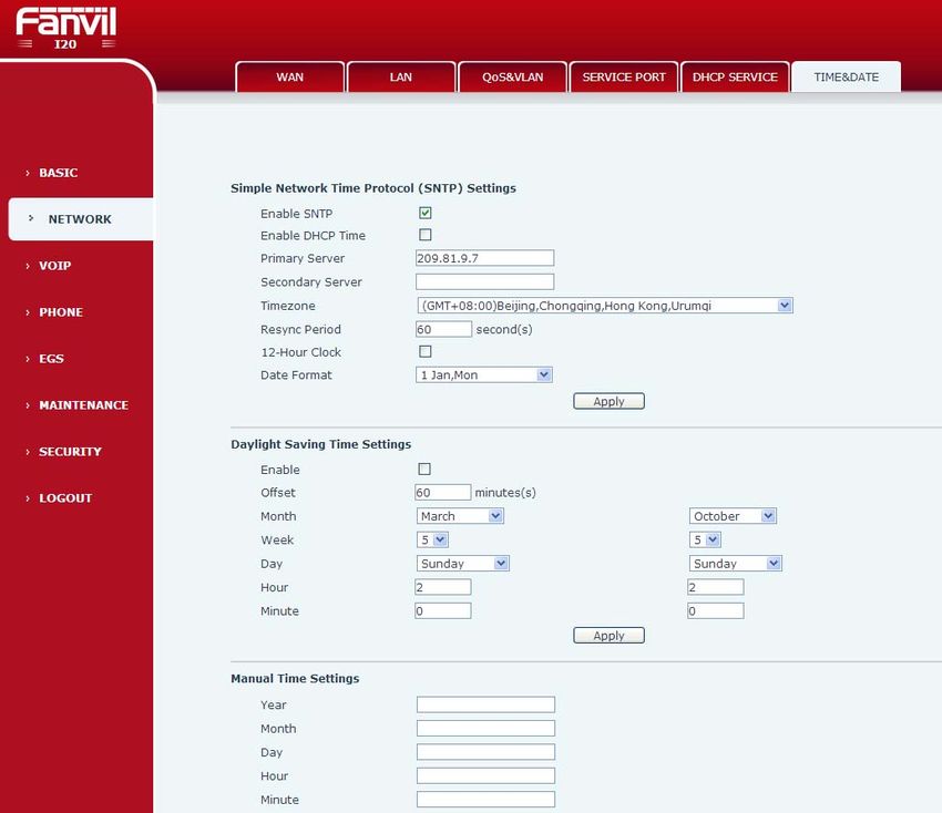
1. Acquaint I20-T
      Voice Intercom I20-T voice entrance guard is a full digital network door phone,its core part adopt Fanvil
mature Voip solution(Broadcom1190 chipset), stable and reliable performance, Hands-free adopting digital
full-duplex mode,Voice loud and clear;generous appearance, solid durable, easy for installation, comfortable
keypad, low power consumption.
    I20-T voice entrance guard support entrance guard control、Voice Intercom、keypad remote to open the door.

1.1. I20-T Front

                                                                                                              4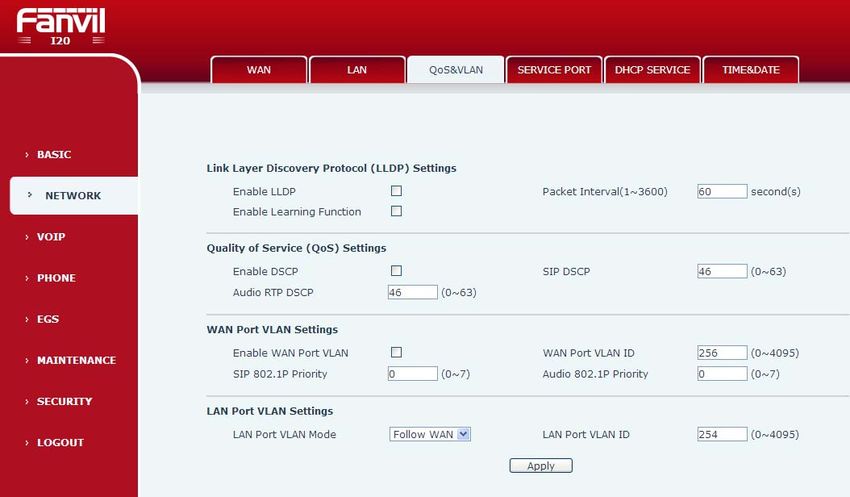
1.2. Key Description
          Key              Chinese                              Function
                         Specification
                                             enter the password to open the door
                                             Or make a calling

                          digit keyboard

                       Programmable          Can be set to a variety of functions,to
                       keyboard              meet the needs of different occasions
                                             standby-light off
                                             ring-2 sec.glitter
                            call status
                                             hold/be hold-1sec. Glitter
                            indicators
                                             communication by telephone
                                             -long bright

                       power led(left)       Long bright after power supply

                         Network and SIP                1 sec. glitter
                                             network failure
                          status indicator   network normal light off
                                light                           3 sec. glitter
                                             registration failure
                             (right)         registration succeed long bright

2. Start Using
    Before you start to use I20-T,please make the following installation:

2.1. Connect the power supply and the network
2.1.1. Connect Network
      In prior to this step, please check if your network can work normally and have capacity
of broadband internet access.
     1. Broadband Router
     Connect network one end with I20-T WAN port,connect the other end with your broadband
router LAN port,then network hardware connection is completed. In most cases,you must set your
I20-T network as DHCP mode.Please refer to the detailed setting ways 3.2.1, set network.

    2. wireless broadband router
                                                                                             5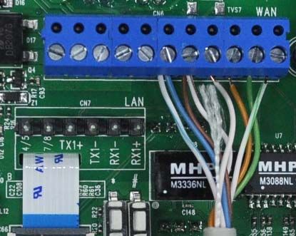
Connect network one end with I20-T WAN port,connect the other end with your ADSL modem
LAN port,then network hardware connection is completed. In most cases,If you are using the TV
cable broadband,you must set your I20-T network as DHCP mode:if you are using ADSL,then you
must set your I20-T network as PPPoE mode.Please refer to the detailed setting ways 3.2.1, set
network.

2.1.2.、Interface Description

2.1.2.1 Network, Power Switch, Electric Lock Connection

                                                               CN6

                             CN7

                                                              CN6
        Output12V           Electric Lock                       WAN(UTP Cable Connection)
        DC                     Driver
        1      2        3           4        5            6              7        8     9     10    11
        V+     GND     NC      COM          NO       POE+               POE-     TX+   TX-   RX-   RX+
        12V DC input   Normally open, normally
                       close port

                                                               CN7
                                                 LAN(UTP Cable Connection)
                                        1             2             3        4    5      6
                                    4/5              7/8        TX+       TX-    RX-   RX+

                                                                                                         6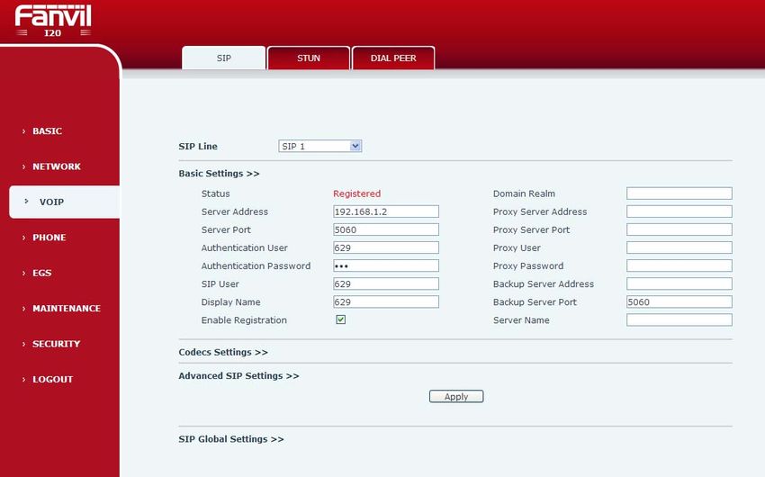
2.1.2.2 Electric Lock Connection Driver Option
JP1 JP1
Outside 1 Inside 1
Driver 2 Driver 2
3 3
4 4
External Power Driving Internal Power Driving
【Notice】When the initial electric current of the lock is less than 500mA/12V, you can
access to the internal driven mode and use the POE of the Voice Access System or 12V
DC to control the the switch of the electric lock ; When the initial electric current of the lock
is more than 500mA/12V, you need to access to the external driven mode(Use specialized
DC power to control the electric lock )
2.1.2.3 Wiring
Relay connection description:
NO:means idle-disconnected contact (normally open)
COM: means a pin contact(middle);
NC:means an idle-connected contact(normally close);
Electric lock Electric Jumper Mode of connection
power supply lock JP1
mode
Internal External NO NC
Inside 1
Driver 2
3
√ √ 4
7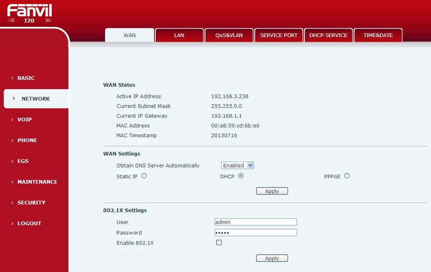
Outside       1
                                 Driver        2
           √         √                         3
                                               4

                                 Inside    1
                                 Driver    2
                                           3
√                          √               4

Electric         lock Electric   Jumper                mode of connection
power          supply lock        JP1
mode
Internal   Externa    NO    NC
           l

                                  Outsid           1
                                  e                2
                                  Driver           3
           √                √
                                                   4

                                                                            8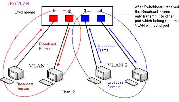
√                      √
                                        Outside   1
                                        Driver    2
                                                  3
                                                  4

2.2. Quick Setting

I20-T Provide a complete function and parameter setting,users may need to have the network and
SIP protocol knowledge for understanding the meaning represented by all parameters.In order to
let I20-T users can quickly enjoy the high quality speech brought by the IP Phone services and low
cost advantage, we especially lists the basic and must set options in this section,which let users
can real-time started without understanding complex SIP protocols.

   In prior to this step,please make sure your broadband Internet online can be normal operation,and complete the
connection of the network hardware. I20-T factory default network mode is DHCP. Thus,only
connect I20-T with DHCP network environment then network can be automatically connected.

     1. Long press # keypad 5 Sec,then waiting for the phone play the IP address;or use
        iDoorPhoneNetwork.exe software to search the IP address
     2. Use IP address log onto WEB server to configurate.
     3. Configurate service provider supplied account on SIP page,user name,service address
        and other Registration required parameters.
     4. Configurate shortcut key on EGS->Function key page.The advice is set to KEY EVENT type,
        value is OK keyboard.
     5.Configurate Door Phone parameter on EGS->EGS page frame.

                                                                                                                9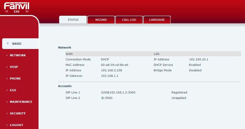
3. I20-T Door Phone Basic Operation
3.1. Answering a Call
When calling come,I20-T will ring,and configurate the shortcut as OK, then can press shortcut
and answer the call.
3.2. Making a Call
Speed Dial
Configurate shortcut as Memory key and setup a number, then press shortcut can call the
configured number immediately.
Keypad Dialing
Configurate shortcut as Dial key. Input wanted number on the keyboard then press short to call.
3.3. End a Call
Configurate shortcut as Release key to end the call.
3.4. Call Records
I20-T provides 100 missed calls、received calls、dialed Calls records,When the storage space
used up,then will update the earnest records. Then the phone power of or reboot,all the call
records will disappear.
Can check all these three type call records on WEB-Basic->call log page
103.5. Door Open Operation
Through the following four ways to open the door:
1. Input the local password on the keyboard to open the door.
2. The door phone call the owner,the owner enter the remote password to open the door.
3. Owner/other phone call the door,then enter the access code and remote password to open the door.
4. Use RFID to open the door.
The access code input errors by low frequency short chirp prompt to door phone and remote user.
input error will be prompted by low-frequency sirens sound.
Password input error is prompted by high frequency chirp,input successfully will be prompted by
high-frequency sirens sound.
When the door opens by playing intermittent beeps for prompt. Timeout after closing door the prompt will be
stoped.
4. Page Configuration
4.1. Ways to configure
4.1.1.Ways to configure
I20-T has two different ways to different users.:
Use web browser (recommendatory way).
Use telnet with CLI command.
4.1.2. Password Configuration
There are two levels to access to phone: root level and general level. User with
root level can browse and set all configuration parameters, while user with
general level can set all configuration parameters except SIP (1-2) or IAX2’s
that some parameters cannot be changed, such as server address and port. User
will has different access level with different username and password.
Manager mode:
User Name:guest
Password:guest
Manager mode:
User Name:admin
Password :admin
4.2. Setting via web browser
When I20-T and PC are connected to network,input phone IP address into Internet Explorer(IP address can
obtain via pressing sysinfo key)http://xxx
.xxx.xxx.xxx/,(if the web log on port is not 80 standard port,then need input http:
//xxx.xxx.xxx.xxx:xxxx/,otherwise it will show can not find a server
11)You can see the web management interface login screen(as below image)。Enter the user name and password
and click on the【Logon】button then can enter into the set menu.
※:If you do not save the settings you changed,next power boot it will back to the previous state unchanged. If
you want to save the settings,after you made the change,please click Maintenance-Config-save then all are
saved,in the process, the phone will immediate effect without reboot.
4.3. WEB Page Functional Explanation
4.3.1. BASIC
4.3.1.1. Status
Status
Field Name Description
Shows the phone current WAN configuration: include WAN IP
Network get way(Static、DHCP、PPPoE)and MAC address,IP,the
default gateway IP address
Shows the phone current SIP LINE 1-2 registered and the
Accounts corresponding number status. The bottom of the page
shows I20-T version number and release date.
4.3.1.2. Wizard
12Wizard
Field Name Description
Telephone network on-line mode, please according to the actual network
environment,select the appropriate network model.This phone provides
three kinds of network online ways:
Static : If your ISP Services provide you with a fixed IP address,you can
choose this.After selecting, you must fill the Static table with:IP Address /
Netmask /Gateway / Primary DNS and other related information. If you don't
know the information,please ask your ISP service provider or network
management personnel for assistance.
DHCP :in this mode,network information will got automatically from the
DHCP server,you need not to manually enter these fields.
PPPoE:select this mode. you must enter the ADSL online account and
password.
You can also reference 3.2.1 Network Settings,and set your network quickly.
Select Static IP MODE,click【NEXT】can simply configurate the network address and
SIP parameters(default as 1 Line)and browse configuration items. Click
【BACK】return to the last page.
13IP Address Please enter your assigned IP addresses.
Subnet Mask Please enter your assigned subnet mask.
IP Gateway Please enter your assigned a default gateway
address.
DNS Domain Set the DNS domain suffix. When the user input in the
DNS domain name address and cannot be resolved,
telephone will add this domain behind the domain
name address then go to resolve.
Primary DNS Please enter your primary DNS server address.
Secondary DNS Please enter your alternate DNS server address.
Display Name Configure display name,able to do when calling in the
called party ( don’t name the caller ) can show this
configuration parameters , and allow input English
letters;
Server Address Configure the SIP registration server address,Support
domain address
Server Port Configure the SIP registration server signaling port
Authentication User Configure the SIP registration account.
Authentication Configure the SIP registration account password.
Password
SIP User Configure the number registered on IP server.
Enable Registration Configurate to allow/prohibit the registration;
14Show your manual configuration details.
Select DHCP MODE,click【NEXT】can simple SIP parameter(defaulted as 1 line)
And browse configuration items. Click【BACK】return to the last page,specific
operation same as Static IP MODE。
Select PPPoE MODE,click【NEXT】can simply configurate online account and
password and SIP parameter(defaulted as 1 line)and browse configuration items.
Click【BACK】return to the last page,specific operation same as Static IP
MODE.
Server name service name,e.g. PPPoE service provider has no
special requirements,the name as the default value is
ok.
User Please enter your ADSL account.
Password Please enter your ADSL password.
Note:After the above operation is completed please click【Finish】button,The
phone will automatically save the current configuration and reboot,
After the successfully reboot can use the registered account to make
calls.
4.3.1.3. Call Log
Through this page can check all call out record.
Call Log
15Field Name Description
Start Time The call log start time.
Duration The call records of talk time.
Dialed Calls This call log is the account of other side and call
protocol and using line.
Type Placed(answered),Missed(missed),Received
(incoming).
4.3.2. Network
4.3.2.1. WAN Config
WAN Config
Field Name Description
Active IP Address The phone current IP;
Current Subnet Mask Subnet Mask;
Current IP Gateway The current default gateway IP;
MAC Address MAC address;
MAC Timestamp Show the time of getting MAC address
16Telephone network on-line mode. Please according to the actual network
environment,choose a suitable network mode. This phone provides three ways
for network online:
static :If your ISP services provide you with fixed IP address,then you
can choose this item. After choosing, you must fill it into Static table:IP
Address / Netmask /Gateway / Primary DNS and other related
information.If you don’t know these information,can ask assistance from
your ISP provider or network management personnel.
DHCP :in this mode,network information will automatically obtain from
DHCP server,you need not to manually enter these fields.
PPPoE:when select this mode,you must enter the ADSL online account
and password.
You can reference 3.2.1 Network Settings,set your network quickly.
Only the phone used in Static mode which need set.
IP Address Please enter your assigned IP addresses.
Subnet Mask Please enter your assigned subnet mask。
IP Gateway Please enter your assigned a default gateway
address.
DNS Domain Set the DNS domain suffix. When the user input in the
DNS domain name address and could not resolute,
after put this domain behind the domain name address then
the phone will go to resolve.
Primary DNS Please enter your DNS service address.
Secondary DNS Please enter your spare DNS service address.
Only when the phone use PPPoE mode need to set.
Server Name service name, e.g. PPPoE Service provider has no
special requirements, this name can be treated as
default value.
User Please enter your ADSL account.
Password Please enter your ADSL code.
Note:
1)After setting the parameters,need click “apply”to make it effective.
2)f changed IP,web page must have no longer responding,at this time
should enter the new address in the address bar can be connected to the
17phone.
3)If system boot and use DHCP to get IP,and DHCP server network address are
the same with system LAN network address,then after server get DHCP IP, add 1
to the last of LAN network address,meanwhile modify LAN DHCP Server allocate
IP address field;After system reboot,WAN access DHCP log on,and DHCP server
provided network address is the same as LAN provided,then WAN will not be
able to get IP access networks.
4.3.2.2. Qos Config
I20-T Terminal system support802.1Q/P protocol,support DiffServ configuration. Meanwhile,VLAN
function can configurate Voice VLA and Data VLAN use different VLAN I.System configuration Data
VLAN,can process the signalling、Audio stream and system and other data stream with different
VLAN ID,which let the applications of VLAN is more flexible.(Below chart is helpful for your
understanding the VLAN using advantages.)
In chart
1,on a two layer switch which not set VLAN,any radio frame is forwarded to all the other ports in
addition to receiving port. e.g,PC A(port 1)After sending the broadcast information,will be
18forwarded to the port 2、3、4.
In chart 2,the switch generate red and blue VLAN;Meanwhile set port 1、2 as red VLAN、port 3、
4 are VLAN. Then A(port 1)send out broadcast frame,switches only will forward it to other port
belongs to a VLAN——port 2 which also belong to red VLAN,Will not be forwarded to the blue port
VLAN. As well,C(port 3)send out broadcast frame,Will only be forwarded to other belong to the
blue port VLAN,Will not be forwarded to belong to the red VLAN ports.
In this way,VLAN by limiting the broadcast frame forwarding range to partition the broadcast
domain. In the above chart for better illustration,use red, blue two colors to identify different VLAN,
in the practice is using “VLAN ID" to distinguish.
Field Name
LLDP Setup Description
Open LLDP Open the phone LLDP Message function
Open Learning Open phone learning LLDP function , After the
Function opening , phone will automatically learn QoS in
switch ,VLAN ID,802.1p,etc.configuration value.If
different,phone will Automatically updated to the value
in switch, synchronization with switches.
Data sending The interval of phone sending data , the unit is
interval second.Default it is 60 seconds.
QOS Setup
Open DiffServ Configurate whether open DiffServ
Signal Dscp Configurate the value of Signal Dscp
Voice Dscp Configurate the value of Voice Dscp
WAN VLAN Setup
Open WAN Port Open the VLAN of WAN port
VLAN
19WAN Port VLAN ID Configurate ID value of VLAN,range is 0-4095
Signal 802.1P Priority Configurate the value of Signal 802.1P,range is 0-7
Voice 802.1P Priority Configurate the value of Voice 802.1P,the range is
0-7
LAN VLAN Setup
LAN Port Vlan Open/forbid Port Vlan
Same as WAN port ID value
Close:Disable Port Vlan
Open:after open it then input different ID value from
WAN port
LAN Port VLAN ID Setup ID value of VLAN,range is 0-4095
4.3.2.3. Service Port
Through this page can set Telnet ,HTTP,RTP port.
SERVICE PORT
Field Name Description
Configurate web browser port,default 80 port, if want
HTTP Port to enhance system security,can modify it to non-80
standard port,save the data after modification,when lo in
again please use this way: http://xxx.xxx.xxx.xxx:xxxx.
Telnet Port Configurate telnet port,default 23port;
RTP Port Range Port Configurate phone RTP and open the starting
port.Allocate this port as dynamic allocation;
RTP Port Quantity Configure the phone allocation RTP port Max
quantity . Default 200 pieces;
Notice:
1)After modifying this page need to save and reboot the phone which can make it come
into force.
202)If change Telnet ,HTTP port number ,it’s better set bigger port number than 1024,
because 1024 port is system reserved port.
3)HTTP port number is set as 0, then forbid the HTTP service.
4.3.2.4. TIME&DATE
According to their own position、configuration time zone and SNTP Server to automatically obtain
time and daylight saving time function,can also according to their need to manually adjust the time.
SNTP
Field Name Description
SNTP Time set
SNTP Configurate whether enable SNTP server
DHCP Time Whether use DHCP dynamic to obtain time,after
enabling,phone will synchronization network time
automatically in certain time
Main Server Configurate phone obtain current time SNTP main
server address.
Backup Server Configurate phone obtain current time SNTP backup
Server address.
Territory Configure the choice for time zone
21Synchronous Query inquiry from the server constantly to synchronize
,default 60 second
12 hours system System can switch to 12 hours,default is 24 hours
Date Format Configure date format
Date Separator Configure date separator
summer time set
Open the Daylight Configure the daylight saving time
Saving Time
Time Change Configure the daylight saving time changing length
Length(Minute )
Month Configure DST the starting month and end month
Week Configure DST the starting week and end week
Date Configure DST the starting date and end date
Hour Configure DST the starting hour and end hour
Minute Configure DST the starting minute and end minute
Manually set the
time
Manually set the time,need firstly disable SNTP service,in the above chart
year、month、date、minute、hour、second every part need filled into and
submit then manual set will succeed.
4.3.3. VOIP
4.3.3.1. SIP Config
Configure the SIP server here.
SIP Config
Field Name Description
22Choose which line configuration of the SIP account,There are two lines to
choose from. Select and click【Load】switch to the line account configuration
Basic setup
Phone SIP registration status display;if the register
registration status will show the registered successfully,Otherwise is
unregistered
server name Name the server
Configure SIP register server address,support domain
Server Address
form address
server port Configure SIP register server signaling port
user name Configure SIP registration account
Password Configure SIP registration account password
Configure the number registered to the SIP server,
Telephone number
if it is empty,then it is not a registered
Configure display names,able to do when calling in
the called party(not name the calling party
Display Name
)can show this configuration parameter,allow input
English letters
Configure proxy server IP address( generally ,SIP
service provide users the use proxy server and
register the same server configuration to provide
services,thus,the proxy server configuration is
Proxy server address usually is the same as the registered server
configuration,if the service providers give different
registered server from the proxy server IP address
configuration , need modify their server
configuration)
proxy server port Configure SIP proxy server signaling port
proxy server account Configure proxy server account
proxy server
Set the proxy server password
password
Configure the SIP local domain name. If the server
does not require a local domain name to specify the
domain name for a SIP terminal,the local domain
can be configured with the same address or domain
local domain name
name server.System to simplify the user input,users
can not enter the local domain name,the system will
automatically get registered address fill in the
content of domain realm.
Configure the backup proxy server address,if the
backup proxy server master agent server address is unavailable,phone
address will enable backup proxy server address
automatically
backup proxy server
Configure the backup proxy server port
port
23Open registration Configure allow/prohibit registration
Codecs
According to the need by navigation on Disable
Disable
Codecs/Enable Codecs list add or remove coding,
Codecs/Enable
and can be used by the priority of the up and down
Codecs
navigation keys to change the coding.
Advance SIP
configuration
Choose call forwarding way. call forwarding(default
it’s close)
close:close call forwarding function
busy:incoming calls when the phone is busy
directly forwarded to the specified number
No answer :incoming calls within a specified time
Forward Type
has not been answered,then forwarded to the
specified number
all the time:incoming call will be transferred to
the specified number before directly
before the forwarding operation,machine indicates
the caller id
Forward Number Configure forward number
If it’s call forward no answer,if nobody answer
Call Forward No incoming call in Call Forward No Answer Delay Time
Answer Delay Time then the calling will be forwarded to specified
number
For the phone supports the transfer of certain
special
Transfer timeout features server, set interval time between sending
“bye” and hanging up after the phone transfers a
call.
Enable the hot line
Configure to enable the hotline number
number
Hot line number Specify Hot Line Number, the phone dial the hot
line number automatically at hands-free mode or
handset mode after warm line time.
Hot line delay time Configure hot line delay time
Open signal Configure whether to support signaling encryption
encryption
Signal encryption key Input signal encryption key
Open voice Configure whether to support voice encryption
encryption
Voice encryption key input speech encryption key
Open the automatic Configure automatic reply
reply
24Automatic response When there is a call in,and over time went
time unanswered,phone will answer it automatically
Configure whether to support rfc4028,refresh the
Open dialogue timer
SIP sessions
Dialogue timeout Configure dialogue timeout
Subscribe information after a successful
Open MWI
registration,can subscribe others’ status or voice
subscription
mails, and so on.
Configure MWI number,realize sip voice message
inform and listen to voice message. When there is a
new voice message,voicemail will flashing lights,
Voicemail Number
pick up and press MWI key will automatic call to
voicemail,and listen to the voice mail,If no new
message, voicemail light is out
Subscribe the packet
retransmission Configure subscription time interval
timeout
Specify the Conference Type, if you select the local,
Meeting Type
you needn’t input the conference number.
meeting room Configure meeting room number,please contact
number your service provider to the meeting room number
Set expire time of SIP server register, default is 60
seconds. If the register time of the server requested
is longer or shorter than the expired time set, the
Registration Expire
phone will change automatically the time into the
time recommended by the server, and register
again.
Enable Service Code Configure whether enable service code
Set the DND On Code, When you press the DND
hot key, the phone will send a message to the
server,
DND On Code and the server will turn on the DND function. Then
any calls to the extension will be rejected by the
server automatically. And the incoming call record
will not be displayed in the Call History.
Set the DND Off Code, When you press the DND
hot key, the phone will send a message to the
DND Off Code
server,
and the server will turn off the DND function
Set the Always CFwd On Code, when you choose to
enable the always forward function on your phone, it
will send message to the server, and the server will
Always CFwd On
turn on the function immediately. When there are
Code
calls to the extension, the server will always forward
it to the set number automatically. And the IP phone
will not show the record in the call history anymore.
Always CFwd Off Set the Always CFwd Off Code, when you choose to
25Code disable the always forward function on your phone,
it will send message to the server, and the server
will
turn off the function immediately.
Set the Busy CFwd On Code, when you choose to
enable the busy forward function v on your phone, it
will send message to the server, and the server will
turn on the function immediately. When there are
Busy CFwd On Code
calls to the extension, the server will forward it to
the set number automatically based the forward
type. And the IP phone will not show the record in
the call history anymore.
Set the Busy CFwd Off Code, when you choose to
disable the busy forward function on your phone, it
Busy CFwd Off Code
will send message to the server, and the server will
turn off the function immediately.
Set the No Answer CFwd On Code, when you
choose to enable the on answer forward function on
your phone, it will send message to the server, and
No Answer CFwd On the server will turn on the function immediately.
Code When there are calls to the extension, the server will
forward it to the set number automatically based the
forward type. And the IP phone will not show the
record in the call history anymore.
Set the No Answer CFwd Off Code, when you
No Answer CFwd Off choose to disable the busy forward function on your
Code phone, it will send message to the server, and the
server will turn off the function immediately.
Set the Anonymous On Code, When you choose to
enable the anonymous call function on your IP
Anonymous On Code phone, it will send information to the server, and the
server will enable the anonymous call function for
your IP phone automatically.
Set the Anonymous Off Code, When you choose to
disable the anonymous call function on your IP
Anonymous Off Code phone, it will send information to the server, and the
server will disable the anonymous call function for
your IP phone automatically.
Configure server detection type,if it’s option,phone
will send option SIP message to server every
Server Detection
configured time ,server respond 200OK to maintain
Type
server detection. If it’s UDP,phone will send option
UDP message to server every configured time
Configure Server detection time interval,if phone
Server detection time enable SIP server detection function,phone will to
interval test whether a server response every configured
time
26User Agent User Agent Terminal
Set DTMF sending mode,there are three:
DTMF_RELAY
DTMF_RFC2833
DTMF Type
DTMF_SIP_INFO
Different VoIP Service providers may provide
different modes.
Local Port Set sip port of each line.
Ring Type Set ring type of each line.
Enable/Disable system to support RFC3581. Via
Enable Via rport
rport is special way to realize SIP NAT.
Enable or disable SIP PRACK function, suggest use
Enable PRACK
the default config.
Set more parameters in contact field; connection
Enable Long Contact
with SEM server.
Convert URI Convert # to %23 when send the URI.
Dial Without
Set call out by proxy without registration;
Registered
Ban Anonymous Call Set to ban Anonymous Call;
Enable DNS SRV Support RFC2782;
Select the special type of server which is encrypted,
Server Type
or has some unique requirements or call flows.
Select SIP protocol version to adapt for the SIP
server which uses the same version as you select.
RFC Protocol Edition For example, if the server is CISCO5300, you need
to change to RFC2543; else phone may not cancel
call normally. System uses RFC3261 as default.
Transport Protocol Set transport protocols, TCP or UDP
Anonymous call Set Anonymous call out safely; Support
Specification version RFC3323and RFC3325;
Enable/Disable Keep Authentication System will
take the last authentication field which is passed the
Keep Authentication authentication by server to the request packet. It will
decrease the server’s repeat authorization work, if it
is enable.
Configure Click-to-Call ;(Need the actual software
Enable Click-to-Call
application support)
Only respond to a When it is called,only respond to one supported
speech codec Codec
Set to use automatically TCP protocol to guarantee
Auto TCP transfer
usability of transport as message is above 1300 byte
Compatible with special server(Support the special
Configure
SIP server-when phone receives
Compatible with
the packets sent from server,phone will use the
special server
source IP address, not the address in via field.)
Enable GRUU Set to support GRUU
27Set to make quotation mark to display name as the
Enable Display name
phone sends out signal, in order to be compatible
Quote
with server.
Enable user=phone by selecting it, it is contained in
Enable user=phone the invite sip message, in order to be compatible
with server.
Enable the missed call log by it, the phone will save
the missed call log into the call history record and
Enable Missed Call
display the missed calls on the idle screen, or won’t
Log
save the missed call log into the call history record
and display the missed calls on the idle screen.
Configure BLF List,BLF List can monitor the state of
Enable BLF List
multiple accounts.
BLF List number Configure BLF List number
SIP Global Settings
Enable the Strict Branch, the value of the branch
must be in the beginning of z9hG4k in via field of
Strict matching the invite sip message received, or the phone won’t
Branch field response to the invite sip message.
Notice: the deployment will become effective in all
sip lines.
Enable Group by selecting it, then the phone enable
Enable Group the sip group backup function.
function Notice: the deployment will become effective in all
sip lines.
Specify the registration failure retry time, if the
phone register failed, the phone will register again
Registration Failure
after registration failure retry time.
Retry Time
Notice: the deployment will become effective in all
sip lines.
4.3.3.2. Stun Config
In this web page, you can config SIP STUN.
STUN: By STUN server, the phone in private network could know the type of
NAT and the NAT mapping IP and port of SIP. The phone might register itself
to SIP server with global IP and port to realize the device both calling and
being called in private
28network.
4.3.5. FUNCTION KEY
4.3.5.1. Function key
1-4 programmable key in phone software(depend on hardware),you can configurate
different feature on each key. You can ref to below indications for each feature, default is NA,
means without any feature settings.
。
1) Type=Hot key
Number 1/2 is the fixed phone number, when press the DSS key, the phone call the fixed phone
number. this phone number can also be set as IP address.
2) Type=Key Event
You can set type as key event, there’re many options in the subtype for your selection.
None
Dial
Release
OK
3) Number Setting
Number1 and number2 is 2 different calling number, when the Dial Mode is ,
29Number1 is the Main number and Number2is the secondary number; When the Dial Mode
is,Number1 is the daytime period and Number2 is the night time period
EGS
EGS,to config the door phone and maintenance the visitor data
Voice Access Configuration
Setting Item Function Initial Value
Open Time Time for open the door, if time is up, the 5s
door will be closed automatically.
After time is up, the call will be ended 120s
Holding Time
automatically.
Remote Openig *
Remote opening password.
Time
Local PIN Local password for the keypad 6789
Tone settings Mute/Short beeps/Long beeps Bell ringing
Keypad mod Dialing and password
Password only(Prohibit call)/Password-Dial
(i20T Valid) input
Displayed on iDoorPhoneNetworkScanner i20 IP door phone
Description
software
Enabling access phone: when remote Enable
Remote
phone calls, input access code first then
phonebook
input password to open the door.
settings
Disabling access phonebook: when remote
30phone calls, input password only.
Eanble open
Provide keyboard function
Touchpad
Enable Card open
Provide card reader function
Reader
mode Primary /secondary
corresponds to the first number in
Dial Mode Select one-button Call function, mode
corresponds to the second number in
one-button Call function
The period between one-button Call function 16s
Time of Switch
to call the first and second number
When select mode, the time to 06:00
Day Start Time
start Day time
When select mode, the time to 18:00
Day End Time
end up Day time
Address of Log
Log server address(IP)
Server
Port of Log
Log server port(0-65535,default:514)
Server
Enable Log Disable
Enable or Disable the log server
Server
Enable Indoor Use to disable or enable the indoor open Disable
Open function
Remote Phonebook
Number Remote phone number
When IP phone calls, it
Access code for visitor. When remote
needs to input
phone calls, if the number is in access list,
Authentication authentication code to
you can input access code to open the
code control voice access
door.
controller.
When owner calls, controller answer
Type of Host automatically, when visitor calls, controller
mute.
Name Card holder’s name
Position Card holder’s position
Department Card holder’s department
Card number RFID’s number
To add new visitor, add the visitor number in and ;Visitor’s Name,
Position and Department is optional; And then Select the ID (Card number) and Access Type
(Visitor or Owner).Press key to add new visitor. The visitor can call the door phone and input
the access code to open the door or use ID card to open the door. Maximum 100 visitors
To modify visitor data, click or key to delete/modify the visitor data, all data
can be modified except calling number
31After you set the log server, i20T will send log data to the log server.
Data format:
MAR 20 11:17:38 5,0003476426,IC Card,I20 IP Door Phone
[Note]:
“”:log level
“MAR 20 11:17:38”: happen time
“5,0003476426,IC Card,I20 IP Door Phone”:logs have include door open time ,Card
number/phone number ,open door type ,device.
4.3.5.2. Door Card Setting
Door Card Setting,to config the ID card and admin the card issue and delete
Door Card Setting
Code Explanation
State ID Card Status Setting:
Normal Status, Wave card to open the door
Card Issuing Status, Update the ID card data to
phone database
Card Revoking Status, Delete the ID card data
from the database
Administrator data table, display the
Administrator Table
administrator ID, Date and Type
Add Administrator, Admin Card Number, Type,
Add Administrator Card Issuer and Revocation. When the ID Card
status is in ,wave admin card to enter
32card issuing mode, and then wave the additional
cards into the database, when the procedure
completed, wave admin card again to enter
Normal status.(Delete card procedure is
same),Maximum 10 Admin Card and 100 visitor
card
To delete Admin Card, select the card number
Delete Administrator
and click
ID card database, display the card number and
Door Card Table
Issuing Date
4.3.5.3. Call Log
Display call history,Maximum 2000 call history,the earlist excessed call history will be deleted
automatically.Right-Click to export Call Log in CSV format
Call Log
Code Explanation
Start Time Time for door openning
Duration Door Opening Duration time
Caller ID(Remote Opening),Card ID number(IC
Peer Calls
card),N/A(local)
Type Door opening type: Local, Remote, IC card
5. Appendix
335.1.1.Specifications:
Protocol SIP 2.0(RFC-3261)
Chipset Broadcom 1190
Key Material Stainless Steel
Key Direct-button 1
Digital Keyboard support
Microphone 1
Amplifier 0.5W/8Ω
Voice Speaker 0.5W/8Ω
Voice Control Adjustable
FDSP Support(AEC)
Protocol RTP
Voice Flow
CODEC G.711, G.729
Power Supply 12V+-15%/1A DC or PoE
PoE 802.3af (Class 0 - 12.95W)
PoE
48V/380mA
10/100BASE-TX s Auto-MDIX,
LAN RJ-45(Keep press key in 7 seconds
PORT to play IP)
Recommended Cable HSYV or better
Always on and Always close highest
Passive Switch
at 30V/1A AC/DC
Active Switched Output 12V/500mA DC
RS232 Support
EM-40XX (125Khz) Support
RFID/IC Card HID Card(125kHz,
Not support
Reader(Optional) 26bit)
M1 Card(13.56MHz) Not support
Shell Material Aluminum Cover、Plastic back case
Operating Temperature -20°C to 70°C
Working Condition
10% - 95%
Relative Humidity
Storage Temperature -40°C to 70°C
Installation Embedded installation (pre-burying)
Structure
Overall Dimension:174.5╳96╳44m
Size pre-burying Mounting Dimension:
148╳80╳36mm
Protection
IP54
Level(Water
proof/Damp proof)
5.1.2. Basic Feature
Support G.711,G.729 codec.
Support SIP 2.0(RFC3261) and related RFC.
Unlock function (swipe or communication)
Water Proof and Dust Proof;
34 Visitor message;
Calling indoor extension for two-way conversation;
Software upgrading on line;
WEB remote management of Terminal malfunction or status;
5.1.3. Schematic Diagram
Rain Cover
Mic
Call/Answer Indicator
Digital Keyboard (Password
input or Number dial)
Red: Power Indicator
Intercom call button
Green: Network/Registration
Indicator
Speaker
Fixing Screw
5.2、Owner Remote Opens the Voice Access Controller by VOIP Phone
1)Owner calls the Voice Access Controller by VOIP Terminal.
2)the Voice Access Controller answers the call automatically.
3)Owner enter Authentication code by VOIP Terminal’s keypad to open the door.
5.3、Card Management
5.3.1 Issue Card Management
35(1) Issue
Input available card number to ID input field, choose Issuer, then press Add to add Issue
Administration Card.
(2)Issue
Input available card number to ID input field, choose “Revocation”, then press Add to add Delete
Administration Card.
(3)Administration Card List
5.3.2Issue User Card
Issue User Card (method 1):
1) Choose “Card Issuing” in “Door Card”.
2) Press “Apply” to submit new User Card.
363) Put IC card on the Reader Sensing Area, and make sure the reader responded.
4) Choose “Normal” in the Card Reader Setting.
5)Press “Apply”.
6)You can check the issuing records in “Door Card Table”
Issue the User Card (Method 2):
1) Put Issue Administration Card on the Reader Sensing Area, the controller is on the state of
issuing.
2) Put IC card on the Reader Sensing Area, and make sure the reader responded.
3) Put Issue Administration Card on the Reader Sensing Area again to sign out issuing, then the
reader is back to the normal state
5.3.3 Delete the user card (Method 1):
1) Choose “Card Issuing” in “Door Card”.
372) Press “Apply” to enter the state of deleting card,
3) Put IC card on the Reader Sensing Area, and make sure the reader responded.
4) Choose “Normal” in the “Card Reader Setting”.
5)Press “Apply” .
Delete the user card (Method 2):
1) Put Issue Administration Card on the Reader Sensing Area, the controller is on the state of
deleting.
2) Put IC card on the Reader Sensing Area, and make sure the reader responded.
3) Put Issue Administration Card on the Reader Sensing Area again to sign out deleting, then the
reader is back to the normal state.
5.3.4、Add Remote Visit Data
(1)Add new number
After finish filling accounts, choose the number for the user, press “Add”.
38(2)Remote Visit Table
39You can also read