Modbus Server Digitally Addressable Lighting Interface (DALI-2) - USER MANUAL - Intesis
←
→
Page content transcription
If your browser does not render page correctly, please read the page content below
Modbus Server
Digitally Addressable Lighting Interface (DALI-2)

                                      USER MANUAL
                              Issue date: 06/2020 r1.1 ENGLISH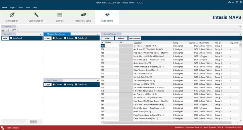
IntesisTM Modbus Server – DALI                                                                       User Manual r1.1 EN

Important User Information
Disclaimer
The information in this document is for informational purposes only. Please inform HMS Industrial Networks of any
inaccuracies or omissions found in this document. HMS Industrial Networks disclaims any responsibility or liability for
any errors that may appear in this document.

HMS Industrial Networks reserves the right to modify its products in line with its policy of continuous product
development. The information in this document shall therefore not be construed as a commitment on the part of
HMS Industrial Networks and is subject to change without notice. HMS Industrial Networks makes no commitment to
update or keep current the information in this document.

The data, examples and illustrations found in this document are included for illustrative purposes and are only
intended to help improve understanding of the functionality and handling of the product. In view of the wide range of
possible applications of the product, and because of the many variables and requirements associated with any
particular implementation, HMS Industrial Networks cannot assume responsibility or liability for actual use based on
the data, examples or illustrations included in this document nor for any damages incurred during installation of the
product. Those responsible for the use of the product must acquire sufficient knowledge in order to ensure that the
product is used correctly in their specific application and that the application meets all performance and safety
requirements including any applicable laws, regulations, codes and standards. Further, HMS Industrial Networks will
under no circumstances assume liability or responsibility for any problems that may arise as a result from the use of
undocumented features or functional side effects found outside the documented scope of the product. The effects
caused by any direct or indirect use of such aspects of the product are undefined and may include e.g. compatibility
issues and stability issues.

© HMS Industrial Networks S.L.U - All rights reserved                                                 URL   https://www.intesis.com
This information is subject to change without notice

                                                                                                                            2 / 47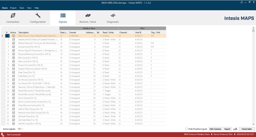
IntesisTM Modbus Server – DALI                         User Manual r1.1 EN

Gateway for integration of DALI devices into Modbus (RTU and
TCP) systems.

  ORDER CODE
  INMBSDAL0640200
  INMBSDAL1280200

© HMS Industrial Networks S.L.U - All rights reserved   URL   https://www.intesis.com
This information is subject to change without notice

                                                                              3 / 47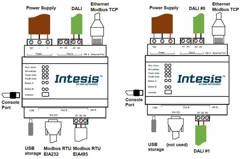
IntesisTM Modbus Server – DALI                                                                                                               User Manual r1.1 EN

INDEX

1 Description ............................................................................................................................................................ 6
            Introduction .................................................................................................................................................... 6
            Functionality .................................................................................................................................................. 8
            Gateway’s capacity ....................................................................................................................................... 8
2 DALI Inteface ........................................................................................................................................................ 9
            Caracteristhics ............................................................................................................................................... 9
3 Modbus interface................................................................................................................................................. 10
            Functions supported .................................................................................................................................... 10
            Modbus RTU ............................................................................................................................................... 10
            Modbus TCP................................................................................................................................................ 10
            Modbus Address Map ................................................................................................................................. 11
       3.4.1       Single DALI device signals .................................................................................................................. 11
       3.4.2       DALI groups’ signals ............................................................................................................................ 19
       3.4.3       Broadcast signals ................................................................................................................................ 21
       3.4.4       Input Devices ....................................................................................................................................... 23
4 Connections ........................................................................................................................................................ 24
            Powering the device .................................................................................................................................... 26
            Connection to DALI channel. ....................................................................................................................... 26
            Connection to Modbus ................................................................................................................................ 26
       4.3.1       Modbus TCP ........................................................................................................................................ 26
       4.3.2       Modbus RTU ........................................................................................................................................ 26
            Connection to PC (Configuration tool) ........................................................................................................ 26
5 Status LEDs and push buttons ........................................................................................................................... 27
6 Set-up process and troubleshooting ................................................................................................................... 29
            Pre-requisites .............................................................................................................................................. 29
            Intesis MAPS. Configuration & monitoring tool for Intesis .......................................................................... 29
       6.2.1       Introduction .......................................................................................................................................... 29
       6.2.2       Connection ........................................................................................................................................... 30
       6.2.3       Configuration tab ................................................................................................................................. 30
       6.2.4       Signals ................................................................................................................................................. 31
       6.2.5       Sending the configuration to Intesis .................................................................................................... 32
       6.2.6       Diagnostic ............................................................................................................................................ 33
            Set-up procedure ......................................................................................................................................... 35
7 Electrical & Mechanical Features ........................................................................................................................ 36
8 Dimensions ......................................................................................................................................................... 37
Annex A – Quick setup and commissioning of a DALI network ............................................................................... 38
            Create project .............................................................................................................................................. 39
            Device declaration in project ....................................................................................................................... 39

© HMS Industrial Networks S.L.U - All rights reserved                                                                                        URL     https://www.intesis.com
This information is subject to change without notice

                                                                                                                                                                          4 / 47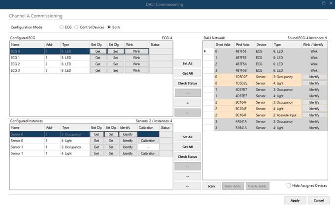
IntesisTM Modbus Server – DALI                                                                                                User Manual r1.1 EN

            Scan and commissioning of devices ........................................................................................................... 41

© HMS Industrial Networks S.L.U - All rights reserved                                                                         URL    https://www.intesis.com
This information is subject to change without notice

                                                                                                                                                        5 / 47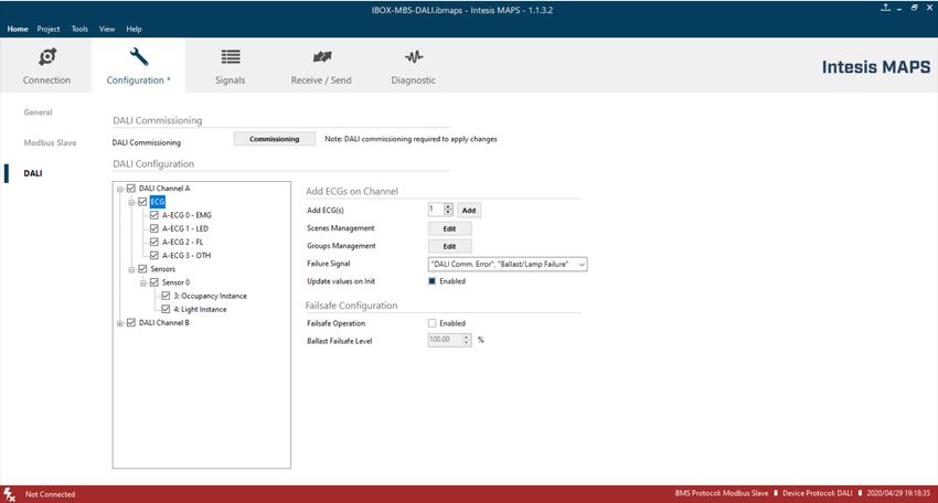
IntesisTM Modbus Server – DALI                                                                       User Manual r1.1 EN

1 Description

         Introduction

This document describes the integration of DALI-2 lighting ballasts and sensors into Modbus compatible devices and
systems using the Intesis Modbus Server to DALI-2 communication gateway.

The aim of this integration is to monitor and control DALI-2 lighting ballasts and sensors (see section 2 for specific
DALI parts), remotely, from your Control Center using any commercial SCADA or monitoring software that includes
a Modbus Master driver (RTU and/or TCP). To do it so, Intesis performs as a Modbus Server, allowing poll and write
requests from any Modbus master device.

Up to 64 addresses for DALI lighting devices (ECGs), and another 64 addresses for Sensors can be fitted in a single
DALI channel, and therefore controlled and monitored from Intesis gateway. Depending on the version of the gateway,
1 line (64 addresses for ECG and 64 addresses for Sensors) or 2 lines (128 addresses for ECG and 128 addresses
for Sensors) are supported.

Version supporting 2 DALI channels does not have support for Modbus RTU – it’s a Modbus TCP-only device.

Intesis needs to be configured using Intesis MAPS software configuration tool. In the software, Modbus and DALI
lighting device parameters must be configured and downloaded to the Intesis gateway.

This document assumes the user is familiar with Modbus and DALI technologies and technical terms.

                          NOTE: Intesis is compatible with Ballasts and sensors implementing the DALI-2
                 !        standard and certified under the DiiA guidelines for testing and certification. Use only
                          DALI-2 devices having the DALI-2 logo with Intesis.

                                           Integration of DALI into
              Modbus TCP / Modbus RTU control systems (product version supporting 1 DALI channel)

© HMS Industrial Networks S.L.U - All rights reserved                                                URL   https://www.intesis.com
This information is subject to change without notice

                                                                                                                           6 / 47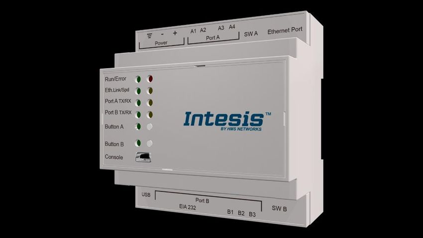
IntesisTM Modbus Server – DALI                                                     User Manual r1.1 EN

                                          Integration of DALI into
             Modbus TCP / Modbus RTU control systems (product version supporting 2 DALI channels)

© HMS Industrial Networks S.L.U - All rights reserved                               URL   https://www.intesis.com
This information is subject to change without notice

                                                                                                          7 / 47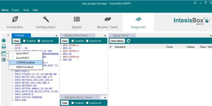
IntesisTM Modbus Server – DALI                                                                                                   User Manual r1.1 EN

         Functionality

IntesisTM continuously polls (reads) all the signals of the DALI ECGs and sensors in each line and maintains the
updated values to be served in Modbus.

When a write is done from Modbus in a gateway's Modbus writeable address, the corresponding command is sent to
the corresponding DALI device.

In the continuous polling process of the DALI channel, if there is no answer, it is indicated with a virtual signal of
communication error for this device in its line.

The IP address and communication parameters for Modbus side of the gateway (TCP or RTU) must be set in the
MAPS configuration tool.

From the configuration tool, it is also possible to scan each DALI channel for available ECGs and/or sensors, add
them in configuration, and configure its individual parameters (short address, preset levels, scenes, etc), according
to their device type or instance.

         Gateway’s capacity

Intesis capacity is listed below:

        Element                                        Max.   Notes

                                                                               Number of independent DALI channels
        Number of DALI channels                         2

        Number DALI ECGs addresses                                     64 DALI ECGs addresses are supported per line
                                                       64
        per line
        Number DALI Sensors                                           64 DALI Sensors addresses are supported per line
                                                       64     The maximin number of devices is limited by the guaranteed power supply of the DALI network. Keep
        addresses per line                                    in mind when dimensioning each DALI channel. See Section 2 for more details.

        Max number of Modbus                                     Number of available signals will vary according to device
                                                       61                                 type
        variables per DALI device
        Max number of Modbus                                     Number of available signals will vary according to device
                                                       16                                 type
        variables per DALI group
        Max number of variables per                                   16 broadcast signals + 16 signals/DALI group + 61
                                                       4176                          signals/DALI device
        LINE
        Number of incoming sockets at                                       6 simultaneous TCP sockets are supported
                                                        6
        Modbus TCP side

There are 2 different models of IntesisTM Modbus Server – DALI with different capacity. The table above shows the
capacity for the top model (with maximum capacity).

The 2 different models allow integrating respectively: 1 or 2 DALI channels.

Their order codes are:

•     INMBSDAL0640200. Model supporting 1 DALI channel (up to 64 DALI ECGs and 64 DALI sensors)
•     INMBSDAL1280200. Model supporting 2 DALI channels (up to 64 DALI ECGs and 64 DALI sensors per channel)

© HMS Industrial Networks S.L.U - All rights reserved                                                                             URL     https://www.intesis.com
This information is subject to change without notice

                                                                                                                                                                  8 / 47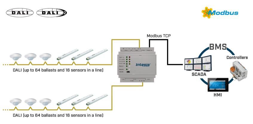
IntesisTM Modbus Server – DALI                                                                   User Manual r1.1 EN

2 DALI Inteface
Intesis gateway and its DALI interface complies with the new DALI-2 (IEC62386) standard thanks to its DALI-2
certification.

Intesis gateway enables the conection of up to 64 DALI/DALI-2 ECGs and 64 DALI-2 sensors. In current version of
the device, the following device types are supported:

      •     General requirements (Part 101)
            • Part 201: DALI Fluorescent lamps (DALI type 0)
            • Part 202: Self-contained Emergency lighting (DALI type 1)
            • Part 207: LED modules (DALI type 6)
            • Others (Multiple DALI types)

      •     Sensors (Part 103):
            • Part 303: DALI-2 Occupancy sensors
            • Part 304: DALI-2 Light sensors

The maximum number of DALI devices (ECGs and/or input devices) depends on the sum current consumption of the
specific devices. Intesis gateway supplies bus power of 235 mA for power supply of the DALI devices, so if all input
devices (sensors) in the bus consumed 5 mA then we could connect 64 ECGs (standard defines max. consumption
allowed for these devices is 2mA) and 16 sensors.

                                     64 ECGs * 2 mA + 16 sensors * 5 mA = 208 mA < 235 mA * 90%

As the standard recommends, don’t use the guaranteed current to calculate the maximum number of DALI devices,
leave 10% of the current for dynamic processes into account.

          Caracteristhics

                                             Element                          Values

                                                                            14 V – 17 V;
                                             DALI voltage (V)
                                                                           typically, 16V
                                             Guaranteed current (mA)
                                                                                235
                                             available per line
                                             Maximum Current (mA)
                                                                                250
                                             available per line

                                             Start-up time (ms)                1500

                                             Shutdown time (sec)                 7

                                             Data transfer rate (bauds)        1200

© HMS Industrial Networks S.L.U - All rights reserved                                             URL   https://www.intesis.com
This information is subject to change without notice

                                                                                                                        9 / 47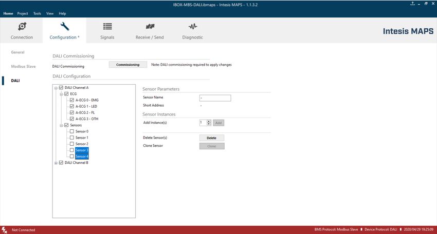
IntesisTM Modbus Server – DALI                                                            User Manual r1.1 EN

3 Modbus interface
         Functions supported

This part is common for Modbus RTU and TCP.

Modbus functions 03 and 04 (Read Holding Registers and Read Input Registers) can be used to read Modbus
registers.

Modbus functions 06 and 16 (Single Multiple Holding Registers and Write Multiple Holding Registers) can be used to
write Modbus registers.

Configuration of poll records is possible between Modbus addresses 0 and 20000. Addresses that are not defined in
section 2.4 (Modbus map of the device) are read-only and will always report 0.

Modbus error codes are supported, they will be sent whenever a non-valid Modbus address is queried.

All registers are 16-bit signed integer, in standard Modbus Big Endian (MSB/LSB) format.

Intesis supports Modbus RTU and Modbus TCP and both interfaces can be used simultaneously.

         Modbus RTU

Modbus RTU is only available in version of the product supporting 1 DALI channel. Product version supporting 2 DALI
channels provides support for Modbus TCP only.

When present, both EIA485 and EIA232 physical layers are supported. Only the lines RX, TX and GND of the EIA232
connector are used (TX and RX for EIA485).

Baud rate can be selected between 1200, 2400, 4800, 9600, 19200, 38400, 56700 and 115200. Parity (none, even
or odd) and stop bits (1 or 2) can be selected as well.

Modbus slave number must be configured and the physical connection (RS232 or RS485) can also be selected.

         Modbus TCP

TCP port to use (default is 502) and keep alive period must be configured.

IP settings of Intesis (DHCP status, own IP, net mask and default gateway) must be configured as well.

© HMS Industrial Networks S.L.U - All rights reserved                                      URL   https://www.intesis.com
This information is subject to change without notice

                                                                                                                10 / 47
IntesisTM Modbus Server – DALI User Manual r1.1 EN
Modbus Address Map
Note that this map only applies when Modbus Addresses parameter is set to Fixed. For more information about configuration of Modbus Addresses parameter see
Intesis MAPS Modbus Server User Manual.
3.4.1 Single DALI device signals
There are up to 94 signals for each DALI device. Their Modbus addresses can be obtained applying the following formula:
Modbus Address = 7000 x CHANNEL + (100 x ECG) + SIGNAL NUMBER
Where:
CHANNEL NUMBER; 0..1 (always 0 if using version with support for 1 DALI channel)
BALLAST NUMBER: 0..63 (ballast short address)
SIGNAL NUMBER: 0..93, see following table
Modbus address from the formula is expressed in link layer format. This is, first register address is 0.
Supported signals vary according to device type. Following abbreviations are done in the table:
• FL: Fluorescent light (device type 0)
• EML: Emergency light (device type 1)
• LED: LED module (device type 6)
• Other.
ECG type
Modbus Address Read/
EML
LED
Register/signal name Possible values
FL
First Address is 0 Write
7000 x channel + (100 x sa)
+0 Ballast / Lamp Failure bit fields
x x x R 0-OK, 1-Ballast / Lamp Failure bi [i = sa - (16 * (line-1))]
channel stands for DALI channel and is 0 or 1 (ECG15-ECG0)
sa stands for short address and is 0 to 63
7000 x channel + (100 x sa) Ballast / Lamp Failure bit fields
x x x R 0-OK, 1-Ballast / Lamp Failure bi [i = sa - (16 * (line-1))]
+1 (ECG31-ECG16)
7000 x channel + (100 x sa) Ballast / Lamp Failure bit fields
x x x R 0-OK, 1-Ballast / Lamp Failure bi [i = sa - (16 * (line-1))]
+2 (ECG47-ECG32)
© HMS Industrial Networks S.L.U - All rights reserved URL https://www.intesis.com
This information is subject to change without notice
11 / 47IntesisTM Modbus Server – DALI User Manual r1.1 EN
ECG type
Modbus Address Read/
EML
LED
Register/signal name Possible values
FL
First Address is 0 Write
7000 x channel + (100 x sa) Ballast / Lamp Failure bit fields
x x x R 0-OK, 1-Ballast / Lamp Failure bi [i = sa - (16 * (line-1))]
+3 (ECG63-ECG48)
7000 x channel + (100 x sa)
x x x R/W Update All ECG Status 0-Update Finished, 1-Trigger Update
+4
7000 x channel + (100 x sa) b7-PwrCycle, b6-MissShAdd, b5-ResetSt, b4-FadeRun,
x x x R Ballast Status
+5 b3-BallLimErr, b2-LampPwrOn, b1-LampFail, b0-BallFail
7000 x channel + (100 x sa)
x x x R Actual Level 0 to 100 %
+6
0-Fluorescent, 1-Emergency, 2 Discharge, 3-Halogen, 4-
7000 x channel + (100 x sa)
x x x R Device Type Incandescent, 5-Digital signal, 6-LED, 7-Switching, 8-
+7
Colour Control
7000 x channel + (100 x sa)
x x x R Physical Minimum Level 0 to 100 %
+8
7000 x channel + (100 x sa)
x x x R Min Level 0 to 100 %
+9
7000 x channel + (100 x sa)
x x x R Max Level 0 to 100 %
+ 10
7000 x channel + (100 x sa)
x x x R Power On Level 0 to 100 %
+ 11
7000 x channel + (100 x sa)
x x x R System Failure Level 0 to 100 %
+ 12
7000 x channel + (100 x sa)
x x x R Fade Time 0 to 15
+ 13
7000 x channel + (100 x sa)
x x x R Fade Rate 1 to 15
+ 14
7000 x channel + (100 x sa)
x x x R/W Arc Power Level 0 to 100 %
+ 15
© HMS Industrial Networks S.L.U - All rights reserved URL https://www.intesis.com
This information is subject to change without notice
12 / 47IntesisTM Modbus Server – DALI User Manual r1.1 EN
ECG type
Modbus Address Read/
EML
LED
Register/signal name Possible values
FL
First Address is 0 Write
7000 x channel + (100 x sa)
x x x R/W Arc Power Off / On 0-Off; 1-100 %
+ 16
7000 x channel + (100 x sa)
x x x R/W Step Down / Up 0-Step Down, 1-Step Up
+ 17
W
7000 x channel + (100 x sa)
x x x (trigge Recall Min Level 1-Recall Min Level
+ 18
r)
W
7000 x channel + (100 x sa)
x x x (trigge Recall Max Level 1-Recall Max Level
+ 19
r)
7000 x channel + (100 x sa)
x x x R/W Go to Scene 0 to 15
+ 20
7000 x channel + (100 x sa)
x x x R/W Store Current Level as Scene 0 to 15
+ 21
7000 x channel + (100 x sa)
x x x R/W Clear/Remove Scene 0 to 15
+ 22
7000 x channel + (100 x sa)
x x x R/W Set Fade Time 0 to 15
+ 23
7000 x channel + (100 x sa)
x x x R/W Set Fade Rate 1 to 15
+ 24
7000 x channel + (100 x sa)
x x x R/W Set Min Level 0 to 100 %
+ 25
7000 x channel + (100 x sa)
x x x R/W Set Max Level 0 to 100 %
+ 26
7000 x channel + (100 x sa)
x x x R/W Set Power-on Level 0 to 100 %
+ 27
7000 x channel + (100 x sa)
x x x R/W Set System-failure Level 0 to 100 %
+ 28
© HMS Industrial Networks S.L.U - All rights reserved URL https://www.intesis.com
This information is subject to change without notice
13 / 47IntesisTM Modbus Server – DALI User Manual r1.1 EN
ECG type
Modbus Address Read/
EML
LED
Register/signal name Possible values
FL
First Address is 0 Write
7000 x channel + (100 x sa)
R Not used Default to 0
+ 29
7000 x channel + (100 x sa)
R Not used Default to 0
+ 30
0-Off, 1-100%, 2-StpUp, 3-StpDwn, 1XX-GoScn, 2XX-
7000 x channel + (100 x sa) StoreScn, 3XX-RmvScn, 1XXX-FdRate, 2XXX-FdTime,
R Multicontrol
+ 31 3XXX-MinLvl, 4XXX-MaxLvl, 5XXX-PwrOnLvl, 6XXX-
SysFailLvl
7000 x channel + (100 x sa)
R Not used Default to 0
+ 32
7000 x channel + (100 x sa)
R Not used Default to 0
+ 33
7000 x channel + (100 x sa)
R Not used Default to 0
+ 34
7000 x channel + (100 x sa)
x R/W Set System-failure Level 0 to 100 %
+ 35
7000 x channel + (100 x sa)
R Not used Default to 0
+ 36
7000 x channel + (100 x sa)
R Not used Default to 0
+ 37
7000 x channel + (100 x sa)
R Not used Default to 0
+ 38
7000 x channel + (100 x sa)
R Not used Default to 0
+ 39
7000 x channel + (100 x sa)
R Not used Default to 0
+ 40
7000 x channel + (100 x sa)
R Not used Default to 0
+ 41
© HMS Industrial Networks S.L.U - All rights reserved URL https://www.intesis.com
This information is subject to change without notice
14 / 47IntesisTM Modbus Server – DALI User Manual r1.1 EN
ECG type
Modbus Address Read/
EML
LED
Register/signal name Possible values
FL
First Address is 0 Write
b7-FunctFail, b6-DurFail, b5-DurTestDelay, b4-
7000 x channel + (100 x sa)
x R Failure Status FunctTestDelay, b3-EmLampFail, b2-BattFail, b1-
+ 42
BattDurFail, b0-CircFail
b7-HardSwOn, b6-HardInhibit, b5-DurTestProg, b4-
7000 x channel + (100 x sa)
x R Emergency Mode FunctTestProg, b3-ExtdEmMode, b2-EmMode, b1-
+ 43
NormMode, b0-RestMode
b7-PhysicSel, b6-Ident, b5-DurTestPend, b4-
7000 x channel + (100 x sa)
x R Emergency Status FunctTestPend, b3-BattFull, b2-DurTestDone, b1-
+ 44
FunctTestDone, b0-InhibitMode
7000 x channel + (100 x sa)
x R Emergency Battery Charge 0 to 100 %
+ 45
7000 x channel + (100 x sa)
x R Next Function Test 0 to 16384 hours
+ 46
7000 x channel + (100 x sa)
x R Next Duration Test 0 to 16384 hours
+ 47
7000 x channel + (100 x sa)
x R Function Test Interval 0-Disabled, 1 to 255 days
+ 48
7000 x channel + (100 x sa)
x R Duration Test Interval 0-Disabled, 1 to 97 weeks
+ 49
7000 x channel + (100 x sa)
x R Test Execution Timeout 0 to 255 days
+ 50
7000 x channel + (100 x sa)
x R Prolong Time 0 to 127,5 minutes
+ 51
7000 x channel + (100 x sa)
x R Duration Test Result 0 to 510 minutes
+ 52
7000 x channel + (100 x sa)
x R Lamp Total Operation Time 0 to 1016 hours
+ 53
7000 x channel + (100 x sa)
x R Emergency Level 0 to 100 %
+ 54
© HMS Industrial Networks S.L.U - All rights reserved URL https://www.intesis.com
This information is subject to change without notice
15 / 47IntesisTM Modbus Server – DALI User Manual r1.1 EN
ECG type
Modbus Address Read/
EML
LED
Register/signal name Possible values
FL
First Address is 0 Write
7000 x channel + (100 x sa)
x R Emergency Min Level 0 to 100 %
+ 55
7000 x channel + (100 x sa)
x R Emergency Max Level 0 to 100 %
+ 56
7000 x channel + (100 x sa)
x R Rated Duration 0 to 510 minutes
+ 57
b7-RelightRestSup, b6-PhysicSelSup, b5-HardInSup, b4-
7000 x channel + (100 x sa)
x R Features AdjsEmLvl, b3-AutoTestCap, b2-SwitchMainCG, b1-
+ 58
MainCG, b0-IntegralEmCG
7000 x channel + (100 x sa)
x R Lamp Emergency Time 0 to 254 hours
+ 59
7000 x channel + (100 x sa)
x W Rest 1-Extinguish Lamp
+ 60
7000 x channel + (100 x sa)
x W Inhibit 1-Start Inhibit mode
+ 61
7000 x channel + (100 x sa)
x W Re-Light/Reset Inhibit 1-Cancel Inhibit Mode
+ 62
7000 x channel + (100 x sa)
x W Start Function Test 1-Start Function Test
+ 63
7000 x channel + (100 x sa)
x W Start Duration Test 1-Start Duration Test
+ 64
7000 x channel + (100 x sa)
x W Stop Test 1-Stop Function/Duration Test
+ 65
7000 x channel + (100 x sa)
x W Reset Function Test Done Flag 1-Reset Function Flag
+ 66
7000 x channel + (100 x sa)
x W Reset Duration Test Done Flag 1-Reset Duration Flag
+ 67
© HMS Industrial Networks S.L.U - All rights reserved URL https://www.intesis.com
This information is subject to change without notice
16 / 47IntesisTM Modbus Server – DALI User Manual r1.1 EN
ECG type
Modbus Address Read/
EML
LED
Register/signal name Possible values
FL
First Address is 0 Write
7000 x channel + (100 x sa)
x W Reset Lamp Time 1-Lamp Emergency Time Reset
+ 68
7000 x channel + (100 x sa)
x R/W Store Test Execution Timeout 0 to 255 days
+ 69
7000 x channel + (100 x sa)
x R/W Store Prolong Time 0 to 127,5 minutes
+ 70
7000 x channel + (100 x sa)
x R/W Store Function Test Interval 0-Disabled, 1 to 255 days
+ 71
7000 x channel + (100 x sa)
x R/W Store Duration Test Interval 0-Disabled, 1 to 97 weeks
+ 72
7000 x channel + (100 x sa)
x R/W Store Emergency Level 0 to 100 %
+ 73
7000 x channel + (100 x sa)
R Not used Default to 0
+ 74
7000 x channel + (100 x sa)
R Not used Default to 0
+ 75
7000 x channel + (100 x sa)
R Not used Default to 0
+ 76
7000 x channel + (100 x sa)
R Not used Default to 0
+ 77
7000 x channel + (100 x sa)
R Not used Default to 0
+ 78
7000 x channel + (100 x sa)
R Not used Default to 0
+ 79
b7-RefMeasurFail, b6-ThermLightLvl, b5-ThermShut, b4-
7000 x channel + (100 x sa)
x R Failure Status CurrProtAct, b3-LoadInc, b2-LoadDec, b1-OpenC, b0-
+ 80
ShortC
© HMS Industrial Networks S.L.U - All rights reserved URL https://www.intesis.com
This information is subject to change without notice
17 / 47IntesisTM Modbus Server – DALI User Manual r1.1 EN
ECG type
Modbus Address Read/
EML
LED
Register/signal name Possible values
FL
First Address is 0 Write
7000 x channel + (100 x sa) b3-dcSuppPoss, b2-acSuppPoss, b1-LEDModInt, b0-
x R Gear Type
+ 81 LEDPowerSInt
7000 x channel + (100 x sa)
x R Dimming Curve 0-Standard Logarithmic Dim Curve, 1-Linear Dim Curve
+ 82
7000 x channel + (100 x sa) b3-HighCurrPulMod, b2-OutCurrContr, b1-AMModePoss,
x R Possible Operating Modes
+ 83 b0-PWMModePoss
b7-PhysicSelSupp, b6-LightLvlRedReq, b5-
7000 x channel + (100 x sa)
x R Features ThermShutReq, b4-CurrProtActReq, b3-LoadIncReq, b2-
+ 84
LoadDecReq, b1-OpenCQ, b0-ShortCQ
7000 x channel + (100 x sa)
x R Reference Running 0-No, 1-Yes
+ 85
7000 x channel + (100 x sa)
x R Current Protector 0-Disabled, 1-Enabled
+ 86
7000 x channel + (100 x sa) b4-NonLogDimCurveAct, b3-HighCurrPulModeAct, b2-
x R Operating Mode
+ 87 OutCurrContr, b1-AMModeAct, b0-PWMModeAct
7000 x channel + (100 x sa)
x R Fast Fade Time 0 to 27
+ 88
7000 x channel + (100 x sa)
x R Min Fast Fade Time 0 to 27
+ 89
7000 x channel + (100 x sa)
x W Reference System Power 1-Trigger DALI Power Referencing
+ 90
7000 x channel + (100 x sa)
x R/W Enable/Disable Current Protector 0-Disable, 1-Enable
+ 91
7000 x channel + (100 x sa)
x R/W Select Dimming Curve 0-Standard Logarithmic Dim Curve, 1-Linear Dim Curve
+ 92
7000 x channel + (100 x sa)
x R/W Store Fast Fade Time 0 to 27
+ 93
© HMS Industrial Networks S.L.U - All rights reserved URL https://www.intesis.com
This information is subject to change without notice
18 / 47IntesisTM Modbus Server – DALI User Manual r1.1 EN
3.4.2 DALI groups’ signals
DALI supports group addressing of ballasts. Up to 16 groups can be defined in a DALI channel. In Intesis, there are up to 16 signals for each DALI group. Their Modbus
addresses can be obtained applying the following formula:
Modbus Address = 7000 x LINE NUMBER + (20 x GROUP NUMBER) + SIGNAL NUMBER
Where:
LINE NUMBER; 0..1 (always 0 if using version with support for 1 DALI channel)
GROUP NUMBER: 0..15 (ballast group)
SIGNAL NUMBER: 6400..6415, see following table
Modbus address from the formula is expressed in link layer format. This is, first register address is 0.
Supported signals vary according to device type. Following abbreviations are done in the table:
• FL: Fluorescent light (device type 0)
• EML: Emergency light (device type 1)
• LED: LED module (device type 6)
• Other
Ballast /
Device type
Modbus Address Read/
Register/signal name Possible values
EML
LED
First Address is 0 Write
FL
7000 * line + (20 * gr) + 6400 0 to 100 %
line stands for DALI channel and is 0 or 1 x x x R/W Arc Power Level
gr stands for DALI group and is 0 to 15
7000 * line + (20 * gr) + 6401 x x x R/W Arc Power Off / On 0-Off; 1-100 %
7000 * line + (20 * gr) + 6402 x x x R/W Step Down / Up 0-Step Down, 1-Step Up
7000 * line + (20 * gr) + 6403 x x x W Recall Min Level 1-Recall Min Level
7000 * line + (20 * gr) + 6404 x x x W Recall Max Level 1-Recall Max Level
© HMS Industrial Networks S.L.U - All rights reserved URL https://www.intesis.com
This information is subject to change without notice
19 / 47IntesisTM Modbus Server – DALI User Manual r1.1 EN
Ballast /
Device type
Modbus Address Read/
Register/signal name Possible values
EML
LED
First Address is 0 Write
FL
7000 * line + (20 * gr) + 6405 x x x R/W Go to Scene 0 to 15
7000 * line + (20 * gr) + 6406 x x x R/W Store Current Level as Scene 0 to 15
7000 * line + (20 * gr) + 6407 x x x R/W Clear/Remove Scene 0 to 15
7000 * line + (20 * gr) + 6408 x x x R/W Set Fade Time 0 to 15
7000 * line + (20 * gr) + 6409 x x x R/W Set Fade Rate 1 to 15
7000 * line + (20 * gr) + 6410 x x x R/W Set Min Level 0 to 100 %
7000 * line + (20 * gr) + 6411 x x x R/W Set Max Level 0 to 100 %
7000 * line + (20 * gr) + 6412 x x x R/W Set Power-on Level 0 to 100 %
7000 * line + (20 * gr) + 6413 x x x R/W Set System-failure Level 0 to 100 %
7000 * line + (20 * gr) + 6414 x R/W Burn-in time Status 0-Stopped, 1-Running
7000 * line + (20 * gr) + 6415 x R/W Burn-in time 0-Stop, 1-Start
© HMS Industrial Networks S.L.U - All rights reserved URL https://www.intesis.com
This information is subject to change without notice
20 / 47IntesisTM Modbus Server – DALI User Manual r1.1 EN
3.4.3 Broadcast signals
Broadcast signals allow to control all ballasts in the same line from an individual signal. Their Modbus addresses can be obtained applying the following formula:
Modbus Address = 7000 x channel + SIGNAL NUMBER
Where:
LINE NUMBER; 0..1 (always 0 if using version with support for 1 DALI channel)
SIGNAL NUMBER: 6800..6815, see following table
Modbus address from the formula is expressed in link layer format. This is, first register address is 0.
Supported signals vary according to device type. Following abbreviations are done in the table:
• FL: Fluorescent light (device type 0)
• EML: Emergency light (device type 1)
• LED: LED module (device type 6)
• Other
Ballast /
Device type
Modbus Address Read/
Register/signal name Possible values
EML
LED
First Address is 0 Write
FL
7000 * line + 6800 0 to 100 %
x x x R/W Arc Power Level
line stands for DALI channel and is 0 or 1
7000 * line + 6801 x x x R/W Arc Power Off / On 0-Off; 1-100 %
7000 * line + 6802 x x x R/W Step Down / Up 0-Step Down, 1-Step Up
7000 * line + 6803 x x x W Recall Min Level 1-Recall Min Level
7000 * line + 6804 x x x W Recall Max Level 1-Recall Max Level
© HMS Industrial Networks S.L.U - All rights reserved URL https://www.intesis.com
This information is subject to change without notice
21 / 47IntesisTM Modbus Server – DALI User Manual r1.1 EN
Ballast /
Device type
Modbus Address Read/
Register/signal name Possible values
EML
LED
First Address is 0 Write
FL
7000 * line + 6805 x x x R/W Go to Scene 0 to 15
7000 * line + 6806 x x x R/W Store Current Level as Scene 0 to 15
7000 * line + 6807 x x x R/W Clear/Remove Scene 0 to 15
7000 * line + 6808 x x x R/W Set Fade Time 0 to 15
7000 * line + 6809 x x x R/W Set Fade Rate 1 to 15
7000 * line + 6810 x x x R/W Set Min Level 0 to 100 %
7000 * line + 6811 x x x R/W Set Max Level 0 to 100 %
7000 * line + 6812 x x x R/W Set Power-on Level 0 to 100 %
7000 * line + 6813 x x x R/W Set System-failure Level 0 to 100 %
0-Off, 1-100%, 2-StpUp, 3-StpDwn, 1XX-GoScn, 2XX-
StoreScn, 3XX-RmvScn, 1XXX-FdRate, 2XXX-FdTime,
7000 * line + 6814 x R/W Broadcast Multicontrol
3XXX-MinLvl, 4XXX-MaxLvl, 5XXX-PwrOnLvl, 6XXX-
SysFailLvl
© HMS Industrial Networks S.L.U - All rights reserved URL https://www.intesis.com
This information is subject to change without notice
22 / 47IntesisTM Modbus Server – DALI User Manual r1.1 EN
3.4.4 Input Devices
Input device signals offer information of the status of each sensor.
Modbus Address = 14000 + (640*LINE NUMBER) + (10 * SENSOR INDEX) + INSTANCE INDEX
Where:
LINE NUMBER; 0..1 (always 0 if using version with support for 1 DALI channel)
SENSOR INDEX: 0..63
INSTANCE INDEX: 0..9
Modbus address from the formula is expressed in link layer format. This is, first register address is 0.
Modbus Address Read/
Register/signal name Possible values
First Address is 0 Write
14000 + (640 * line) + (10 * Occupancy InputValue / Light [0, 1, 2, 3] - [Vacant + No Mov, Vacant + Mov, Occupied + No Mov,
SensorIDX) + InstanceIDX R Occupied + Mov] / Lux
InputValue
line stands for DALI channel and is 0 or 1
© HMS Industrial Networks S.L.U - All rights reserved URL https://www.intesis.com
This information is subject to change without notice
23 / 47IntesisTM Modbus Server – DALI User Manual r1.1 EN
4 Connections
Find below information regarding the Intesis connections available.
INMBSDAL0640200 (1 DALI channel) INMBSDAL1280200 (2 DALI channels)
Figure 4.1 Gateway’s connections
Power Supply
Must use NEC Class 2 or Limited Power Source (LPS) and SELV rated power supply. Respect polarity applied of
terminals (+) and (-). Be sure the voltage applied is within the range admitted (check section 7). The power supply
can be connected to earth but only through the negative terminal, never through the positive terminal.
Ethernet / Modbus TCP
Connect the cable coming from the IP network to the connector ETH of the gateway. Use an Ethernet CAT5 cable.
If communicating through the LAN of the building, contact the network administrator and make sure traffic on the port
used is allowed through all the LAN path (check the gateway user manual for more information). With factory settings,
after powering up the gateway, DHCP will be enabled for 30 seconds. After that time, if no IP is provided by a DHCP
server, the default IP 192.168.100.246 will be set.
PortA / DALI #0
Connect the DALI bus to connectors A4 (+), A3 (-) of gateway’s PortA. Intesis provides 16VDC (+/-2%) DALI voltage
to the bus.
PortB / Modbus RTU (INMBSDAL0640200 / 1 DALI channel)
Connect the EIA485 bus to connectors B1 (-), B2 (+) and B3 (SNGD) of gateway’s PortB. Respect the polarity.
Remember the characteristics of the standard EIA485 bus: maximum distance of 1200 meters, maximum 32 devices
connected to the bus, and in each end of the bus it must be a termination resistor of 120 Ω. The gateway has an
internal bus biasing circuit that incorporates the termination resistor. If you install the gateway in one of the ends of
the bus, then do not install an additional termination resistor in that end.
© HMS Industrial Networks S.L.U - All rights reserved URL https://www.intesis.com
This information is subject to change without notice
24 / 47IntesisTM Modbus Server – DALI User Manual r1.1 EN
PortB / DALI #1 (INMBSDAL1280200 / 2 DALI channels)
Connect the DALI bus to connectors B2 (+), B1 (-) of gateway’s PortA. Intesis provides 16VDC (+/-2%) DALI voltage
to the bus.
Console Port
Connect a mini-type B USB cable from your computer to the gateway to allow communication between the
Configuration Software and the gateway. Remember that Ethernet connection is also allowed.
USB
Connect a USB storage device (not a HDD) if required. Check port caractheristics on section 7.
Ensure proper space for all connectors when mounted (see section 8).
© HMS Industrial Networks S.L.U - All rights reserved URL https://www.intesis.com
This information is subject to change without notice
25 / 47IntesisTM Modbus Server – DALI User Manual r1.1 EN
Powering the device
A power supply working with any of the voltage range allowed is needed (check section 7). Once connected the RUN
led (Figure above) will turn on.
WARNING! In order to avoid earth loops that can damage the gateway and/or any other equipment connected to it,
we strongly recommend the use of DC power supplies, floating or with the negative terminal connected to earth.
Never use a DC power supply with the positive terminal connected to earth.
Connection to DALI channel.
Connect + and – terminals of the DALI bus of your DALI channel to Intesis’ DALI port. Bus has polarity, but most
DALI devices are polarity insensitive.
Having your DALI channel powered up, you can perform a quick DALI connectivity test by pressing Port A / Port B
buttons:
- When pressing Port A / Port B button, a broadcast command that will toggle the ballasts between 100%
and 0% level will be sent.
- After 30s timeout of not pressing the button, ballasts will return back to its original level.
DALI commands coming from Modbus will continue to be executed while doing this test.
Connection to Modbus
4.3.1 Modbus TCP
Connect the communication cable coming from the network hub or switch to the Ethernet port of Intesis. The cable
to be used shall be a straight Ethernet UTP/FTP CAT5 cable.
4.3.2 Modbus RTU
Connect the communication cable coming from the Modbus network to the port marked as Port B of Intesis. Connect
the EIA485 bus to connectors B1 (-), B2 (+) and B3 (SNGD) of gateway’s PortB. Respect the polarity.
Remember the characteristics of the standard EIA485 bus: maximum distance of 1200 meters, maximum 32 devices
(without repeaters) connected to the bus, and in each end of the bus it must be a termination resistor of 120 Ω. The
gateway has an internal bus biasing circuit that incorporates the termination resistor. Bus biasing and termination
resistor for EIA485 can be enabled for PortB by means of a dedicated DIP switch.
Connection to PC (Configuration tool)
This action allows the user to have access to configuration and monitoring of the device. Two methods to connect to
the PC can be used:
• Ethernet: Using the Ethernet port of the Intesis.
• USB cable: To connect the device to the PC, the USB cable supplied should be plugged to the USB Console
port.
© HMS Industrial Networks S.L.U - All rights reserved URL https://www.intesis.com
This information is subject to change without notice
26 / 47IntesisTM Modbus Server – DALI User Manual r1.1 EN
5 Status LEDs and push buttons
LED Colour Indication
Run Off No power
Green Device powered and working.
Error Off No error
Red Error
Port A (Tx/Rx) – DALI #0 Off There is no activity on this port.
Tx - Blinking green Every data packet sent to UFO device it
blinks
Rx – Blinking yellow Every data packet received from UFO
device it blinks
Port B (Tx/Rx) – DALI #1 Off There is no activity on this port.
(INMBSDAL1280200 – 2 Channels) Tx - Blinking green Every data packet sent to UFO device it
blinks
Rx – Blinking yellow Every data packet received from UFO
device it blinks
Port B (Tx/Rx) – Modbus RTU Off There is no activity on this port.
(INMBSDAL0640200 – 1 Channel) Tx - Blinking green Every data packet sent to the network it
blinks
Rx – Blinking yellow Every data packet received from an
slave device it blinks
Button A – DALI #0 Off / Red Indicates status of last command sent
from the button (On-
RECALL_MAX_LEVEL, Off-OFF)
After 30 secs of not pushing the button,
the LED turns OFF and next time the
button is pushed it will begin with
RECALL_MAX_LEVEL
Button B – DALI #1 Off / Red Indicates status of last command sent
(INMBSDAL1280200 – 2 Channels) from the button (On-
RECALL_MAX_LEVEL, Off-OFF)
After 30 secs of not pushing the button,
the LED turns OFF and next time the
button is pushed it will begin with
RECALL_MAX_LEVEL
Button B – Modbus RTU Off / Red It doen’t have any functionality
(INMBSDAL0640200 – 1 Channel)
© HMS Industrial Networks S.L.U - All rights reserved URL https://www.intesis.com
This information is subject to change without notice
27 / 47IntesisTM Modbus Server – DALI User Manual r1.1 EN
Push button Functionality
Button A – DALI #0 Sends to broadcast, alternatively: RECALL_MAX_LEVEL, OFF
Button B – DALI #1 Sends to broadcast, alternatively: RECALL_MAX_LEVEL, OFF
(INMBSDAL1280200 – 2 Channels)
Button B – Modbus RTU It doesn’t have any functionality. It can be configured from Intesis MAPS
(INMBSDAL0640200 – 1 Channel) software
© HMS Industrial Networks S.L.U - All rights reserved URL https://www.intesis.com
This information is subject to change without notice
28 / 47IntesisTM Modbus Server – DALI User Manual r1.1 EN
6 Set-up process and troubleshooting
Pre-requisites
It is necessary to have the Modbus RTU or TCP master/client device (BMS side device) operative and properly
connected to the corresponding port of the gateway. It is also required to have a DALI installation connected to the
gateway, in its respective DALI port/s.
Connectors, connection cables, PC for the usage of the Configuration Tool and other auxiliary material, if needed,
are not supplied by Intesis for this standard integration.
Items supplied with this product for this integration are:
• Intesis gateway.
• Link to download the configuration tool.
• USB Console cable to communicate with Intesis.
• Product documentation.
Intesis MAPS. Configuration & monitoring tool for Intesis
6.2.1 Introduction
Intesis MAPS is a Windows® compatible software developed specifically to monitor and configure Intesis new
generation gateways.
The installation procedure and main functions are explained in the Intesis MAPS User Manual. This document can
be downloaded from the link indicated in the installation sheet supplied with the Intesis device or in the product
website at www.intesis.com
In this section, only the specific case of DALI to Modbus will be covered.
Please check the Intesis MAPS user manual for specific information about the different parameters and how to
configure them.
© HMS Industrial Networks S.L.U - All rights reserved URL https://www.intesis.com
This information is subject to change without notice
29 / 47IntesisTM Modbus Server – DALI User Manual r1.1 EN
6.2.2 Connection
To configure the Intesis connection parameters press on the Connection button in the menu bar.
Figure 6.1 MAPS connection
6.2.3 Configuration tab
Select the Configuration tab to configure the connection parameters. Three subsets of information are shown in this
window: General (Gateway general parameters), Modbus Slave (Modbus interface configuration) and DALI (DALI
channel/s and DALI devices configuration).
© HMS Industrial Networks S.L.U - All rights reserved URL https://www.intesis.com
This information is subject to change without notice
30 / 47IntesisTM Modbus Server – DALI User Manual r1.1 EN
Figure 6.2 Intesis MAPS configuration tab
General, Modbus Slave and DALI tabs are explained in Intesis MAPS user manual for Intesis Modbus Server Series.
6.2.4 Signals
All available registers, its corresponding description and other main parmaters are listed in the signals tab. Depending
on the configuration of the Modbus Addresses parameter, on the Modbus Slave tab, active signals may vary, and
edition may be allowed or not.
For more information about configuration of Modbus Addresses parameter, see Intesis MAPS Modbus Server User
Manual on:
https://www.intesis.com/docs/intesis-maps-modbus-server_user-manual
© HMS Industrial Networks S.L.U - All rights reserved URL https://www.intesis.com
This information is subject to change without notice
31 / 47IntesisTM Modbus Server – DALI User Manual r1.1 EN
Figure 6.3 Intesis MAPS Signals tab
6.2.5 Sending the configuration to Intesis
When the configuration is finished, follow the steps to program the gateway.
1.- Click on Save button to save the project to the project folder on your hard disk (more information in Intesis
MAPS User Manual).
2.- You will be prompted to generate the configuration file to be sent to the gateway.
a.- If Yes is selected, the file containing the configuration for the gateway will be generated and saved
also into the project folder.
b.- If NO is selected, remember that the binary file with the project needs to be generated before the
Intesis starts to work as expected.
3.- Press the Send File button to send the binary file to the Intesis device. The process of file transmission
can be monitored in the Intesis Communication Console window. Intesis will reboot automatically once the
new configuration is loaded.
© HMS Industrial Networks S.L.U - All rights reserved URL https://www.intesis.com
This information is subject to change without notice
32 / 47IntesisTM Modbus Server – DALI User Manual r1.1 EN
Figure 6.4 Intesis MAPS Receive/Send tab
After any configuration change, do not forget to send the configuration file to the Intesis using the
button “Send”.
6.2.6 Diagnostic
To help integrators in the commissioning tasks and troubleshooting, the Configuration Tool offers some specific tools
and viewers.
In order to start using the diagnostic tools, the connection with the Gateway must be stablished.
The Diagnostic section is composed by two main parts: Tools and Viewers.
• Tools
Use the tools section to check the current hardware status of the box, log communications into
compressed files to be sent to the support, change the Diagnostic panels’ view or send commands
to the gateway.
• Viewers
In order to check the current status, viewer for the Internal and External protocols are available. It is
also available a generic Console viewer for general information about communications and the
gateway status. User can use a Signals Viewer to simulate the BMS behavior or to check the current
values in the system.
© HMS Industrial Networks S.L.U - All rights reserved URL https://www.intesis.com
This information is subject to change without notice
33 / 47IntesisTM Modbus Server – DALI User Manual r1.1 EN
Figure 6.5 Diagnostic
More information about the Diagnostic section can be found in Intesis MAPS user manual for Intesis Modbus Server
Series.
© HMS Industrial Networks S.L.U - All rights reserved URL https://www.intesis.com
This information is subject to change without notice
34 / 47IntesisTM Modbus Server – DALI User Manual r1.1 EN
Set-up procedure
1. Install Intesis MAPS on your laptop, use the setup program supplied for this and follow the instructions given by
the Installation wizard.
2. Install Intesis in the desired installation site. Installation can be on DIN rail or on a stable not vibrating surface
(DIN rail mounted inside a metallic industrial cabinet connected to ground is recommended).
3. If using Modbus RTU, connect the communication cable coming from the EIA485 port of the Modbus RTU
installation to the port marked as Port B of Intesis (More details in section 4).
If using, Modbus TCP, connect the communication cable coming from the Ethernet port of the Modbus TCP
installation to the port marked as Ethernet Port of Intesis (More details in section 4).
4. Connect the communication cable coming from DALI network to the port marked as Port A of Intesis (More details
in section 4).
5. If using two DALI channels, connect communication cable coming from second DALI network to the port marked
as Port B of Intesis (More details in section 4).
6. Power up Intesis. The supply voltage should be any of the voltage range allowed (check section 7). Take care of
the polarity of the supply voltage applied.
WARNING! In order to avoid earth loops that can damage Intesis and/or any other equipment connected to
it, we strongly recommend the use of DC power supplies, floating or with the negative terminal connected to
earth. Never use a DC power supply with the positive terminal connected to earth.
7. If you want to connect using IP, connect the Ethernet cable from the laptop PC to the port marked as Ethernet of
Intesis (More details in section 4).
If you want to connect using USB, connect the USB cable from the laptop PC to the port marked as Console of
Intesis (More details in section 4).
8. Open Intesis MAPS, create a new project for Modbus and select the INMBSDAL---0200-Template project.
9. Modify the configuration as desired, save it and download the configuration file to Intesis as explained in section
6.2.5 .
10. Visit the Diagnostic section, enable COMMS and check that there is communication activity, some TX frames
and some other RX frames. This means that the communication with the Centralized Controller and Modbus
Master devices is OK. In case there is no communication activity between Intesis and the Centralized Controller
and/or Modbus devices, check that those are operative: check the baud rate, the communication cable used to
connect all devices and any other communication parameter.
Figure 6.6 Enable COMMS
© HMS Industrial Networks S.L.U - All rights reserved URL https://www.intesis.com
This information is subject to change without notice
35 / 47IntesisTM Modbus Server – DALI User Manual r1.1 EN
7 Electrical & Mechanical Features
Plastic, type PC (UL 94 V-0)
Size: Coin 20mm x 3.2mm
Net dimensions (dxwxh): 90x88x56 mm
Enclosure Battery Capacity: 3V / 225mAh
Recommended space for installation (dxwxh): 130x100x100mm
Type: Manganese Dioxide Lithium
Color: Light Grey. RAL 7035
Wall. Mini Type-B USB 2.0 compliant
Mounting Console Port
DIN rail EN60715 TH35. 1500VDC isolation
Per terminal: solid wires or stranded wires (twisted or with ferrule) Type-A USB 2.0 compliant
Terminal Wiring 1 core: 0.5mm2… 2.5mm2 Only for USB flash storage device
(for power supply and USB port (USB pen drive)
2 cores: 0.5mm2… 1.5mm2
low-voltage signals) Power consumption limited to 150mA
3 cores: not permitted
(HDD connection not allowed)
Button A: Check the user manual
1 x Plug-in screw terminal block (3 poles) Push Button
Button B: Check the user manual
Power Positive, Negative, Earth
Operation
24VDC +/-10% 0°C to +50°C
Temperature
1 x Ethernet 10/100 Mbps RJ45 Operational
Ethernet 5 to 95%, no condensation
2 x Ethernet LED: port link and activity Humidity
1 x DALI port (Plug-in screw terminal block orange 2 poles) Protection IP20 (IEC60529)
1500VDC isolation from other ports
10 x On board LED indicators
DALI power consumption: 240mA
Port A 1 x Error LED
Voltage rating: 16VDC
1 x Power LED
1 x Plug-in screw terminal block green (2 poles)
LED 2 x Ethernet Link/Speed
Reserved for future use
Indicators 2 x Port A TX/RX
Switch A 1 x DIP-Switch for serial EIA485 configuration: 2 x Port B TX/RX
(SWA) Reserved for future use 1 x Button A indicator
1 x Button B indicator
INMBSDAL0640200
1 x Serial EIA232 (SUB-D9 male connector)
Pinout from a DTE device
1500VDC isolation from other ports
(except PORT B: EIA485)
1 x Serial EIA485 Plug-in screw terminal block (3 poles)
A, B, SGND (Reference ground or shield)
PORT B 1500VDC isolation from other ports
(except PORT B: EIA232)
INMBSDAL1280200
1 x DALI port (Plug-in screw terminal block green 2 poles)
1500VDC isolation from other ports
DALI power consumption: 240mA
Voltage rating: 16VDC
1 x DIP-Switch for serial EIA485 configuration:
Position 1:
ON: 120 Ω termination active
Switch B Off: 120 Ω termination inactive
SWB)
Position 2-3:
ON: Polarization active
Off: Polarization inactive
© HMS Industrial Networks S.L.U - All rights reserved URL https://www.intesis.com
This information is subject to change without notice
36 / 47IntesisTM Modbus Server – DALI User Manual r1.1 EN
8 Dimensions
56 mm (h)
88 mm (w) 90 mm (d)
Recommended available space for its installation into a cabinet (wall or DIN rail mounting), with space enough for
external connections
100 mm (h)
100 mm (w)
130 mm (d)
© HMS Industrial Networks S.L.U - All rights reserved URL https://www.intesis.com
This information is subject to change without notice
37 / 47IntesisTM Modbus Server – DALI User Manual r1.1 EN
Annex A – Quick setup and commissioning of a DALI network
This section provides a brief summary on commissioning a DALI channel using MAPS software tool. The process of
commissioning involves:
- Scanning the existing ballasts (ECGs) and sensors (Input Devices) in the DALI network
- Identifying their physical location
- Obtaining or setting up device short addresses
- Obtaining or editing devices configuration parameters (preset levels, scenes, groups addressing…)
In that process, using MAPS, two workflows are possible for the commissioning:
1. “Device declaration first”: First declaring or instantiating in MAPS the envisaged (planned) devices in the
installation, setting up values for all their configuration parameters, and then scanning the network for
existing devices. Process finalizes with assignation and download of planned configuration parameters
(including short addresses) with existing devices in the installation.
2. “Existing devices scan first”: Aternatively, and more common, it is possible to scan first the DALI network
for existing devices, obtain their existing configuration (which will be default/factory if the devices are
new), then change these parameters to match the desired ones (short address, preset levels, scenes…)
and load the devices with the new configuration.
Typically, “Existing devices scan first” method will be used when all commissioning is done in the installation itself,
as it starts with a DALI bus scan. “Device declaration first” allows to do some work in advance, defining the
configuration parameters for the ballasts and sensors before accessing the actual installation. It is possible to
understand the “Device declaration first” as a previous step that can (but not must) be done before effectively
scanning the network for devices (“Existing devices scan first”), in order to advance configuration work (definition of
preset levels, DALI groups, scene values, …).
It is perfectly possible to mix the two methods. This is, configure a certain number of ballasts declaring them in MAPS
(“Device declaration first”), and once in the installation, assign their parameters to existing ballasts and sensors.
Whenever more devices are installed, they can be added by scanning them in the network (“Existing devices scan
first”) and changing its configuration parameters to match the desired ones (without previous instantiation of them in
MAPS).
© HMS Industrial Networks S.L.U - All rights reserved URL https://www.intesis.com
This information is subject to change without notice
38 / 47IntesisTM Modbus Server – DALI User Manual r1.1 EN
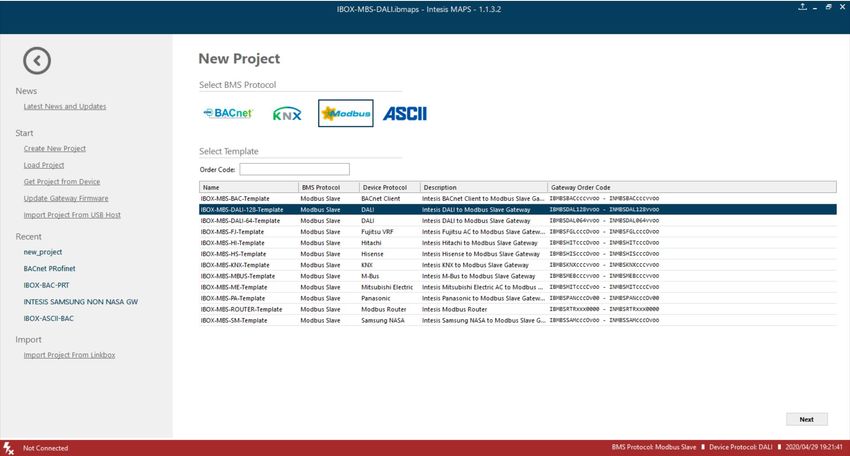
Create project
You will need to create a new project, to do so, select ‘Create New project’ in MAPS start screen, and choose the
appropriate template according to your device model (1 or 2 DALI channels / 64 or 128 max DALI devices):
Figure A.1 New project creation
Device declaration in project
Once new project has been created, DALI devices can be added to the configured project, without the need of
scanning them in bus.
As mentioned above, this allows defining its configuration parameters (preset values, groups, scenes, …) before
having actual access to the installation.
To do so, go to the ‘Configuration’ tab of MAPS, and select the ‘DALI’ section.
In it, choose the channel where you want to instantiate the devices (A or B are possible in case of having the product
version supporting 2 DALI channels), then select ECG node to add new ballasts, or select Sensors node to add new
sensors.
© HMS Industrial Networks S.L.U - All rights reserved URL https://www.intesis.com
This information is subject to change without notice
39 / 47You can also read