THE CAM USER INTERFACE GUIDE - VISUALCAM 2021 - MECSOFT CORPORATION
←
→
Page content transcription
If your browser does not render page correctly, please read the page content below
The CAM User
Interface Guide
      VisualCAM 2021
            Tuesday, February 23, 2021

                                         MecSoft Corpotation
                                           © Copyright 1998-2021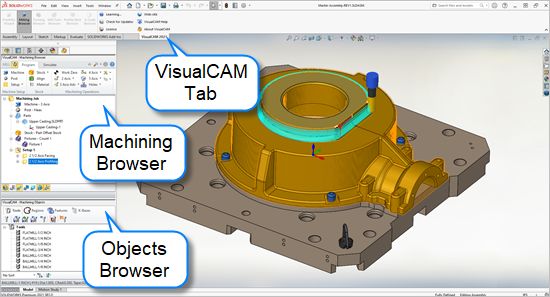
The CAM User Interface Guide
                        by MecSoft Corporation

User Notes:
________________________________
________________________________
________________________________
________________________________
________________________________
________________________________
________________________________
________________________________
________________________________
________________________________
________________________________
________________________________
________________________________
________________________________
________________________________
________________________________
________________________________
________________________________
________________________________
________________________________
Contents                       2

Table of Contents

Quick Start                                                                                                                                                                                  3

Resource Guide                                                                                                                                                                               6

About this Guide                                                                                                                                                                             7

User Interface                                                                                                                                                                               8

VisualCAM for SOLIDWORKS Menu Item                                                                                                                                                           9

MILL Browsers                                                                                                                                                                              10
            1 Machining
                  ...................................................................................................................................
                           Browser                                                                                                                    10
                       Brow ser Toggle
                                     ..........................................................................................................................................................
                                           Tabs                                                                                                                                                 10
                       Program Tab .......................................................................................................................................................... 11
                       Sim ulate Tab .......................................................................................................................................................... 15
            2 Machining
                  ...................................................................................................................................
                           Objects (Mobs) Browser                                                                                                     19
                       Tools Tab    .......................................................................................................................................................... 20
                       Regions Tab .......................................................................................................................................................... 23
                       Features Tab .......................................................................................................................................................... 26
                       K-Bases Tab .......................................................................................................................................................... 30

CAM Preferences                                                                                                                                                                            32
            1 Geometry
                  ................................................................................................................................... 32
            2 Features
                   ................................................................................................................................... 34
            3 Stock................................................................................................................................... 36
            4 Cutting
                    ...................................................................................................................................
                        Tools                                                                                                                           37
            5 Feeds...................................................................................................................................
                     & Speeds                                                                                                                          39
            6 Machining
                  ...................................................................................................................................
                           Preferences                                                                                                                41
                       Multi-threading
                                    ..........................................................................................................................................................
                                         Manager                                                                                                                                               42
            7 Output
                  ...................................................................................................................................
                     Control                                                                                                                          44
            8 Toolpath
                   ................................................................................................................................... 46
            9 Simulation
                  ................................................................................................................................... 48
           10 User Interface
                   ................................................................................................................................... 52
           11 Licensing
                   ................................................................................................................................... 56

                Index                                                                                                                                                                      60

© 2021 MecSoft Corporation

                                                                                                                                                                                                     2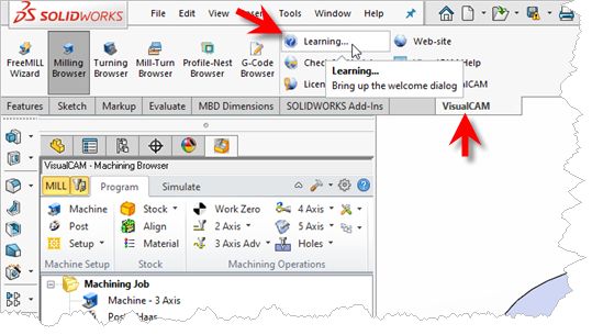
3      The CAM User Interface Guide

Quick Start

                   VISUALCAM 2021 for SOLIDWORKS

                        Prefer Printed Documentation? Check Here!
      Quick Start Guides for each VisualCAM for SOLIDWORKS module are available in both PDF and
      Video format. Refer to the following information to access these resources:

              What's New
              What's New in VisualCAM 2021 for SOLIDWORKS

              The Complete Quick Start Video Play List
              Here is a link to the complete 2021 Video Play List

              How to Access the Quick Start Guide Documents
              To help you quickly get started in working with each module, select one of the Help
              buttons located on the VisualCAM for SOLIDWORKS Learning Resources dialog.
              You will find:
              · Quick Start Guides
              · What's New documents
              · Online Help links
              The Quick Start Guides will help you step through an example tutorial which will
              illustrate how to use the module. To access the Learning Resources dialog:
              1. From the SolidWorks menu bar, locate the VisualCAM main menu and select Learn ...

                                                                                © 2021 MecSoft Corporation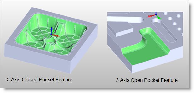
Quick Start   4

                                          To access the Learning Resources dialog for SolidWorks 2015 and above

                     2. Select a document from the Learning Resources dialog to get started using the
                        module of your choice.

                             You can also select the Open Quick Start Files Folder button located at the bottom
                         of the dialog to open the Quick Start folder where the source files (start and
                         completed versions) are located.

© 2021 MecSoft Corporation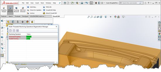
5   The CAM User Interface Guide

                                   Learning Resources Dialog

                                                               © 2021 MecSoft Corporation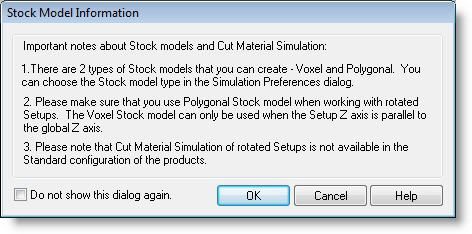
Resource Guide 6
Resource Guide
Download this PDF Guide for a list of the available VisualCAM for SOLIDWORKS Resources.
2021 VisualCAM for SOLIDWORKS Resource Guide
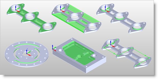
The 2021 VisualCAM for SOLIDWORKS
Resource Guide!
18 Pages
Lists PDF downloads and Online resources including Quick Start
Guides, Reference Guides, Exercise Guides, Tutorials and
More.
Click Here to download this Free guide!
© 2021 MecSoft Corporation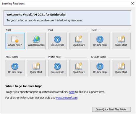
7      The CAM User Interface Guide

About this Guide

                    VISUALCAM2021 for SOLIDWORKS

      Welcome to the CAM User Interface Guide! You can use this guide as a quick reference to the
      following automation features you will find in VisualCAM for SOLIDWORKS.
          MILL Browsers
          Learn about each tab and function on the Machining Browser and the Machining Objects
          Browser in the MILL module.
          TURN Browsers
          Learn about each tab and function on the Machining Browser and the Machining Objects
          Browser in the TURN module.
          CAM Preferences
          Learn about the CAM Preferences dialog and how each of these preferences can help you use
          VisualCAM for SOLIDWORKS more efficiently.

                                                                                © 2021 MecSoft Corporation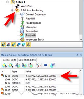
User Interface   8

User Interface
          The VisualCAM for SOLIDWORKS MILL module adheres to the Windows standard for user interface
          design and integrated into the SolidWorks screen seamlessly.

                     MILL Module Displayed
                     A screen shot of the VisualCAM for SOLIDWORKS MILL module running inside of
                     SolidWorks is shown below:

                                           A screen shot of MILL module running inside of SolidWorks

                     The VisualCAM for SOLIDWORKS MILL Interface
                     There are 3 main interface objects created when MILL module is loaded.
                         1. VisualCAM menu bar entry under SolidWorks menu bar
                         2. Machining Browser (Mops) window
                         3. Machining Objects (Mobs) Browser window

© 2021 MecSoft Corporation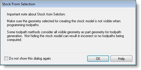
9      The CAM User Interface Guide

VisualCAM for SOLIDWORKS Menu Item
      When VisualCAM for SOLIDWORKS is loaded successfully it will add a menu item titled VisualCAM
      2021 to the Tools menu in SolidWorks 2015 or higher. (For SolidWorks 2010 - 2014 the VisualCAM
      2021 menu is added to the main SolidWorks menu bar.) Selecting this menu item will create a
      drop down menu as shown below.

                                               VisualCAM menu Item

      To run the MILL module, select MILL from the VisualCAM 2021 drop down menu.
      Selecting MILL displays the Milling Browser window in the SolidWorks user interface. If the
      FreeMILL or TURN Browser is currently open selecting this will switch the display to the MILL
      Browser.

                                                                                  © 2021 MecSoft Corporation
MILL Browsers 10
MILL Browsers
The MILL Browser allows management of various entities or objects that can be created in the
VisualCAM for SOLIDWORKS MILL module. There are 2 browsers in VisualCAM – Machining
Operations Browser (Mops) and Machining Objects Browser (Mobs).
6.1 Machining Browser
The Machining Browser, sometimes called the Machining Operations (Mops) Browser, has two
main modes of operation represented by tabs at the top of the window. These are Program and
Simulate. Each tabbed view also incorporates a ribbon toolbar at the top. These toolbars group all
of the functions associated with the type of object in the tab.
The Machining Operations (Mops) Browser
The Machining Operations (MOps) Browser, Program Tab
6.1.1 Browser Toggle Tabs
Tabs available on the Machining Browser that allow you to toggle the display of both the
Machining Browser and the Machining Objects Browser.
Browser Toggle Tabs
© 2021 MecSoft Corporation11 The CAM User Interface Guide
Locating the Brow ser Toggle Tabs
Selecting this tab toggles between the MILL , TURN, MILL-TURN and Profile-NEST
Machining Browser.
Select this tab to toggle the display of the Machining Objects Browser.
6.1.2 Program Tab
Selecting the Program tab in the Mops Browser provides access for specifying Machine, Stock and
the definition of Machining Operations.
The Machining Operations (Mops) Browser, Program Tab
© 2021 MecSoft CorporationMILL Browsers 12
The Machining Operations (MOps) Browser, Program Tab
Machine Setup Pane
Available Configuration
Summary Xpress Standard Expert Professional Premium
(XPR) (STD) (EXP) (PRO) (PRE)
Machine Setup Pane
Machine Tool Setup: Sets the Machine for 2½ axis, 3 axis, 4 axis
and 5 axis operations.
Set Post-Processor Options: Allows you to set the Current Post
Processor, posted file naming conventions, posted file
extension, program to display the posted file.
Create Setup Operations: Sets the Coordinate System for
Machining. The orientation of the part can be set using Orient
Part, orientation of the Coordinate System can be defined
under CSYS Setup for 3+2 machining and Rotate Table Setup for
4 axis table rotate operations.
© 2021 MecSoft Corporation13 The CAM User Interface Guide
Stock Pane
Available Configuration
Summary Xpress Standard Expert Professional Premium
(XPR) (STD) (EXP) (PRO) (PRE)
Stock Pane
Create Stock Model: Allows you to create Stock geometry. User
can also delete a Stock geometry by selecting Delete Stock.
Align Part and Stock Models: Aligns stock model to part. This
function is especially useful when the part model and the stock
model are created without regard to their respective positional
locations.
Define Stock Material: Allows you to select a material from the
material list.
Machining Operations Pane
This section allows you to create machining operations. MILL module allows you to
create multiple machining operations in a part file. This is a powerful feature that allows
you to create an entire sequence of machining operations that is necessary to create the
part model from the stock model. This set of operations can additionally be archived
with the part file and retrieved at a later time with no loss of information.
Available Configuration
Summary Xpress Standard Expert Professional Premium
(XPR) (STD) (EXP) (PRO) (PRE)
Machining Operations Pane
Set Current Work Coordinate Zero: Allows you to set the work
Coordinate zero (Origin) for the part being programmed.
Create 2 ½ Axis Milling Operations: Provides access to 2 ½
Axis Machining Methods.
Create 3 Axis Milling Operations: Provides access to 3 Axis
Machining Methods
© 2021 MecSoft CorporationMILL Browsers 14
Create 3 Axis Advanced Milling Operations: Provides access
to 3 Axis Machining Methods.
Create 4 Axis Milling Operations: Provides access to 4 Axis
Machining Methods
Create 5 Axis Milling Operations: Provides access to 5 Axis
Machining Methods.
Holes: Provides access to Drilling, Tapping, Boring and
Reverse Boring Machining Methods.
Create Miscellaneous Operations: Allows you to create,
Machine Control Cycles, Fixture Offset and XY Instance
operations.
Knowledge Base Operations: Allows saving and loading of
Machining operations to and from a knowledge base.
Utilities: Provides access to G Code Editor and Post
Process Generator.
Set CAM Preferences: Provides access to specify Color,
User Interface, Machining, Simulation and Feeds Speeds
Preferences.
Minimize/Maximize Ribbon bar: Minimizes & Maximizes the
ribbon bar.
Display Help Content: Open On-line Help document.
Display Toggle Toolbar
This toolbar is located at the base of the Machining Browser and has the following
controls:
© 2021 MecSoft Corporation15 The CAM User Interface Guide
Available Configuration
Summary Xpress Standard Expert Professional Premium
(XPR) (STD) (EXP) (PRO) (PRE)
Stock Model Visibility: Turn on/off stock model
Material Texture Visibility: Turn on/off material texture visibility
Toolpath Visibility: Turn on/off toolpath display
Hidden Toolpath Visibility: Turn the hidden portions of toolpaths
on/off.
Display Toolpath Levels: Displays tool path by Z levels
World CSYS Visibility: Turns on/off of World Coordinate System
display.
Machine CSYS Visibility: Turns on/off of Machine Coordinate System
display.
6.1.3 Simulate Tab
Select the Simulate tab to run cut material simulations and toolpath animations. This tab also
provides controls to vary the simulation speed, set the simulation preferences and toggle the
display state of various simulation components.
Machining Operations Browser, Simulate Tab
© 2021 MecSoft CorporationMILL Browsers 16
The Machining Operations (MOps) Browser, Simulate Tab
Simulate Tab Functions
The following controls are available on the Simulate tab:
Available Configuration
Summary Xpress Standard Expert Professional Premium
(XPR) (STD) (EXP) (PRO) (PRE)
Create Stock Model: Allows you to create Stock geometry. You
can also delete a Stock geometry by selecting Delete Stock.
Perform Toolpath Simulation or Animation: Allows you to
perform cut material simulation with tool animation.
Simulate Next Toolpath Block: Simulation is performed in steps
as defined by the display interval in the simulation
preferences.
Simulate Next Toolpath Z Levels: Simulation is performed in
separate Z levels.
© 2021 MecSoft Corporation17 The CAM User Interface Guide
Simulate to End: Simulation is performed without updating the
display until the end of the toolpath.
Pause Toolpath Simulation: Pause/Stop the simulation.
Part Stock Compare*: Compare the simulated model with the
part geometry. The part geometry must contain surface/solid
geometry.
Stop Toolpath Simulation: Exits Simulation Mode. Pause
simulation before exiting simulation mode.
Simulation Speed: Varies simulation speed
Set Simulation Preferences: Provides access to simulation
preferences.
Simulate by Moves: Switches from Simulate by Distance to
Simulate by Motions.
Simulate Toolbar Functions
The following toolbar controls are available on the Simulate tab:
Available Configuration
Summary Xpress Standard Expert Professional Premium
(XPR) (STD) (EXP) (PRO) (PRE)
Part Model Visibility: Turn on/off part model display during
simulation.
Stock Model Visibility: Turn on/off stock model
Material Texture Visibility: Turn on/off material texture
visibility
© 2021 MecSoft CorporationMILL Browsers 18
Toolpath Visibility: Turn on/off toolpath display
Hidden Toolpath Visibility: Turn the hidden portions of
toolpaths on/off.
World CSYS Visibility: Turns on/off of World Coordinate System
display.
Machine CSYS Visibility: Turns on/off of Machine Coordinate
System display.
Tool Visibility: Turn on/off tool display during simulation.
Holder Visibility: Turn on/off tool holder display during
simulation
Machine Tool Visibility**: Turn on/off machine tool display
during simulation
Follow Toolpath Display: The toolpath is displayed as it follows
the behind the movement of the tool (i.e., you will only see the
toolpath after the tool passes.
Trace Toolpath Display: The toolpath is not displayed as it
follows the behind the movement of the tool (i.e., you will only
see the toolpath before the tool passes.
Segment Toolpath Display: The toolpath is only displayed for
the segment that the tool is currently on.
Simulation Display State: Use this to select the display state for
the simulation. Select from Default, Tool, Mop or Texture. See
Machining Operation Properties for setting unique simulation
colors for each Mop (Machining Operation) in your Machining
© 2021 MecSoft Corporation19 The CAM User Interface Guide
Job.
The status bar displays the number of Goto motions of the currently simulated
operation.
6.2 Machining Objects (Mobs) Browser
The Machining Objects Browser has multiple tabs located at the top to work with different types
of machining objects such as Tools, Regions, K-Bases, etc. Each tabbed view also incorporates a
toolbar at the top. The toolbars on each tab group all of the functions associated with the type of
object in the tab.
The Machining Objects Browser can be toggled on and off by selecting the toggle button located at
the top left corner of the Machining Browser. This toggle button is shown below.
The Machining Objects (Mobs) Browser
Locating the Machining Objects Browser toggle tab
The Machining Objects (MObs) Browser
The status bar displays the currently selected tool, spindle speed and cut feedrate.
Machining Objects Browser Tabs
Available Configuration
Summary Xpress Standard Expert Professional Premium
(XPR) (STD) (EXP) (PRO) (PRE)
© 2021 MecSoft CorporationMILL Browsers 20
Machining Operations Pane
Tools tab: Allows you to create, edit, tools and tool libraries.
Regions tab: Allows you to create and edit pre-define regions
for use with machining operations.
Features tab: Allows you to detect machinable features and
perform automatic and interactive feature machining.
K-Bases tab: Allows you to load, edit and save machining
knowledge bases.
6.2.1 Tools Tab
Selecting the Tools tab under the Machining Objects Browser brings up the tool manager. The tool
manager lists all of the tools currently defined as well as the tools that are in use in machining
operations. Users can edit a tool by double clicking the tool button in the browser. A tool can be
deleted by selecting the tool from the Tools browser, right click cut or use the delete key from the
keyboard.
The Machining Objects (Mobs) Browser, Tools Tab
The Machining Objects (MObs) Browser, Tools Tab
VisualCAM for SOLIDWORKS supports 2 types of tool library file format *.vkb and *.csv
(*.vkb is recommended).
Tools Tab Functions
© 2021 MecSoft Corporation21 The CAM User Interface Guide
Available Configuration
Summary Xpress Standard Expert Professional Premium
(XPR) (STD) (EXP) (PRO) (PRE)
Tools Tab Functions
Create/Edit Tools: This button brings up the tool dialog that
enables the creation and saving of tools. All milling, drilling and
user defined tools can be created here. Refer to Tool section
for a detailed description on creating tools and defining tool
parameters.
Load Tool Library: The load tool library button enables the
loading of a previously saved tool library. Refer to the
following section for additional information - Load Tool Library
Select Tools from Library: The select tool library button enables
you to select tools from a previously saved tool library. Refer to
the following section for additional information - Select Tools
from Library
Save Tool Library: This button enables the created tools to be
saved in a tool library file. The file can be saved in the desired
directory and read in when required. Refer to the following
section for additional information - Save Tool Library
Unload Tool Library: This button will unload the current Tool
Library.
List Tools: The button brings up all the tool properties
associated with the tools currently recorded in the current MILL
session. Refer to the following section for additional
information - List Tools
Compute Tool Holder Collisions*: Determines tool holder
collision with the part geometry. Refer to the following section
for additional information - Compute Tool Holder Collisions
Right-click Options on Tools
© 2021 MecSoft CorporationMILL Browsers 22
You can right-click on a Tool listed in the Mobs Browser to perform various functions.
These are listed below:
Right-click Options on a Tool
Edit
Displays the Create/Edit Tool dialog allowing you to edit the Tool parameters.
Rename
Allows you to Rename the selected tool.
Cut / Copy / Paste
These options allow you to Cut or Copy the selected Tool to the Windows
Clipboard and then Paste it back to the Tools list to create a new tool using the
previous tool as a template.
Add to Library
This allows you to Add the selected Tool to an exiting Tool Library *.csv data file.
Preview
This will display a Preview of the selected Tool in the Graphics Window similar
to how the Tool displays during Simulation. The Tool will display at the origin of
the MCS for the current operation.
Tools Toolbar Functions
The following Tool Sorting rules (when set) will apply to both the Tools tab of the
Machining Objects Browser and the Create/Select Tools dialog.
© 2021 MecSoft Corporation23 The CAM User Interface Guide
Sorting Selector: This allows you to sort the tool list. You can
select No Sort or sort by Name, Number, Type and Diameter.
Sort in Ascending/Descending Order: This icon acts like a toggle to
switch between Ascending and Descending sort order.
List on the Tool used in Machining Operations: Toggle this icon to
list ONLY the tools currently assigned to an operation. Note: You
must Generate an operation for the assigned tool to be listed.
If you do not see any of your tools listed, check to make sure
this icon is toggled OFF. If no operations are using tools yet
and this icon is ON, then no tools will be listed!
Tools Sorted by Used
Tools Sorted by Name
Tools Status Bar
The status bar displays the currently selected tool, tool tip radius & angle, spindle speed
and cut feedrate.
Status Bar, Tools Tab, Machining Objects Browser
6.2.2 Regions Tab
Selecting the Regions tab under the Machining Objects (Mobs) Browser displays the Machining
Regions manager.
© 2021 MecSoft CorporationMILL Browsers 24
Regions Tab, Machining Objects (Mobs) Browser
Regions Tab, Machining Objects (MObs) Browser
The Regions tab allows you to:
· Create Pre-defined Machining Regions from curves (sketches) and flat areas
· Specify Start Point for closed curves
· Reverse Curve Direction
· Create Automatic Bridge Points
· Manually Define Bridge Points
· Edit Bridge Points
· Edit predefined regions
· Delete Bridge Points
These can then be selected as machining features for generating machining operations.
Regions Tab Functions
Create Machining Region Set
Creates a group that can contain one or more machining regions.
Select Curve
Allows you to select curves (sketches) as pre-defined machining regions. Each
contiguous region is listed as a sub-region of the Machining Regions Set. You
can edit each sub-region independently.
Select Surface Edge Areas
Select surface edge curves to create a region.
Flat Areas Selection Filter
Displays a flat area region selection filter dialog which allows you to choose the
type of boundary areas to select for flat area selection.
© 2021 MecSoft Corporation25 The CAM User Interface Guide
Select Flat Areas
Creates a curve forming the boundary of select flat areas. The flat area could be
a face of solid or a plane.
If the Flat Area contains multiple closed curves (such as a flat rectangle
with a hole in the middle of it) and no Flat Area Selection Filters are set
then each closed curve is defined as a separate Curve Region and placed under
one Machining Region Set in the Mobs browser. Each Curve Region can then
be edited separately such as deleting, reversing direction or changing the start
point.
Select Start Point
Allows you to pick a start point for a selected curve region.
Reverse Cut Direction
Allows you to reverse curve direction for a selected curve region.
Automatic Bridge Points on Selections
Automatically creates bridge points for a selected curve region.
Manual Bridge Points on Selections
Allows manual selection of bridge points for a selected curve region.
Delete All Bridge Points in Selections
Deletes all bridge point for a selected curve region.
Edit Bridge Point in Selections
This allows the editing of a bridge point for the selected curve region.
Note: If you double-click on this icon, the command remains modal (i.e., active)
until you right-click in the drawing window to cancel it. This functionality allows
you to quickly edit all of your bridge points without having to re-execute the
command.
Edit Bridge Points in Selected Region - Modal
Clone Region
Allows you to clone selected machining regions for geometrically identical
© 2021 MecSoft CorporationMILL Browsers 26
curves.
Right-click Options on Predefined Regions
You can right-click on a Curve Region listed in the Mobs Browser to perform various
functions. These are listed below:
Right-click Options on a Tool
Edit
You can right click on a Region (Curve, Surface Edge, or Flat Area) to edit and
then add or remove geometries to the region.
Rename
This allows you to Rename the selected Region.
Delete
Use this Delete the selected Region from the set.
6.2.3 Features Tab
Selecting the Features tab under the Machining Objects Browser displays the Feature Manager. It
allows you to create and work with detected features from your 3D solid model. See
Understanding Feature Machining in VisualCAM for SOLIDWORKS for important information about
Machining Features.
Important: Machining Features can ONLY be extracted from poly-surface
models (i.e., solid models). If your part model is not a solid, you must
"stitch" all surfaces into a poly-surface prior to Creating Machining Features!
The Features tab (Machining Objects Browser)
© 2021 MecSoft Corporation27 The CAM User Interface Guide
The Machining Objects (MObs) Browser, Features Tab
Features Tab Commands
Available Configuration
Summary Xpress Standard Expert Professional Premium
(XPR) (STD) (EXP) (PRO) (PRE)
Features tab Command Icons
-
Performs Automatic Feature Detection (AFD) from your part model
based all possible machining Orientations. See Automatic Feature
Detection (AFD) for more information.
- -
Performs Interactive Feature Detection (IFD) by selecting a face from
your part model to define the machining Orientation. See Interactive
Feature Detection (IFD) for more information.
-
Allows you to Set Filters for Feature Detection so that only certain
feature types or hole diameters are detected. See Set Filters for
Feature Detection for more information.
-
© 2021 MecSoft CorporationMILL Browsers 28
Allows you to list all of your detected features. See List Features for
more information.
-
Allows you to setup a features knowledge base. See: Setup Features
Knowledge Base.
-
Allows you to create a hole feature machining operation. See: Create
Hole Feature Machining Operation.
-
Allows you to perform Automatic Feature Machining (AFM) based on
the default (AFM) Knowledge Base defined in the Features section of
the CAM Preferences dialog. See Automatic Feature Machining (AFM)
for more information.
Features tab Toolbar Icons
-
This icon Toggles the display of Features in the drawing window. It is
located at the bottom of the browser when the Features tab is active.
Feature Identification on Cursor Highlight
After you have performed either AFD or IFD on your part model, you can move the cursor
over a part feature and its identification name will display. This is the name created for
the feature and listed in the Features tree.
Feature Identification on Cursor Highlight
Feature Types Recognized
The feature types recognized are listed in the table below:
Feature Types Detected
© 2021 MecSoft Corporation29 The CAM User Interface Guide
Hole Prismatic Open Boss General
Pocket Prismatic Pocket
Pocket (3 Axis)
Slot Open Slot T-Slot V-Slot Open General
Pocket
(3 Axis)
Planar Face Fillet Chamfer Stepped Silhouette
Prismatic
Pocket
Some 2 Axis Feature Examples
© 2021 MecSoft CorporationMILL Browsers 30
Some 3 Axis Feature Examples
6.2.4 K-Bases Tab
Selecting the K-Bases tab under the Machining Objects Browser displays the Knowledge Base
manager.
The Machining Objects (Mobs) Browser, K-Bases Tab
The Machining Objects (MObs) Browser, K-Bases Tab
K-Bases Tab Functions
Available Configuration
Summary Xpress Standard Expert Professional Premium
(XPR) (STD) (EXP) (PRO) (PRE)
Features tab Command Icons
-
Load Knowledge Base: Allows you to select a machining
operations knowledge base to load.
© 2021 MecSoft Corporation31 The CAM User Interface Guide
-
Save Knowledge Base: Allows saving of knowledge bases which
can be archived and used across other files.
Refer to the following sections for a detailed description on Knowledge base
· Knowledge Base
· Load Knowledge Base from Machining Objects Browser
© 2021 MecSoft CorporationCAM Preferences 32
CAM Preferences
You can set various CAM Preferences that will be saved even after you exit the program.
Select the Preferences icon from the Machining Browser. When you install a new
VisualCAM for SOLIDWORKS update you are choose to import your CAM Preferences from one
version to the next.
The CAM Preferences Icon
Set CAM System Preferences menu item
7.1 Geometry
You can set the colors to display various objects using this dialog. To change each of the color
settings in this dialog select the colored button next to the item of interest. This will bring up the
color selection dialog, which can be used to choose the color needed. Once a color has been
selected the button will change its color to the selected one.
Dialog Box: CAM Preferences > Geometry
© 2021 MecSoft Corporation33 The CAM User Interface Guide
CAM Preferences > Geometry
Region Colors
Containment Region
Use this color selector to set the display color for Containment Regions (i.e., your Control
Geometry).
Avoid Region
Use this color selector to set the display color for Avoid Regions (i.e., your Control
Geometry).
Surface Colors
Drive Surfaces
Use this color selector to set the display color for Drive Surfaces (5 Axis).
Check Surfaces
Use this color selector to set the display color for Check Surfaces (5 Axis).
Fixture Colors
Fixture
Use this color to represent fixture geometry.
© 2021 MecSoft CorporationCAM Preferences 34
7.2 Features
Here you can set preferences related to Features (for MILL module only). Note: These
preferences are not available in XPR (Xpress) configuration.
Dialog Box: CAM Preferences > Cutting Tools
CAM Preferences > Features
User Interface
Show Features Tab
Check this box to display the Features tab. If this is not checked, then you will not be
able to perform Feature Recognition.
Show Features Tab in Machining Objects Browser
Check this box if you prefer to have the Features tab appear in the Machining Objects
Browser (to the right of the Regions tab). If this box is not checked, the Features tab will
appear in the Machining Browser (to the left of the Program tab) as shown below.
© 2021 MecSoft Corporation35 The CAM User Interface Guide
Display Colors
This section allows you to set the default Feature Color and default Selected Feature
Color.
Feature Color
Here you can set the default Feature Color. When an operation is selected from the
Machining Job tree of the Machining Browser, that is derived from a Machining Feature,
the feature is highlighted using this color.
Selected Feature Color
Here you can set the default Selected Feature Color. When a Machining Feature is
selected from the Features tab of the Machining Objects Browser, the feature is
highlighted using this color.
Display Transparency
This refers to how transparent feature colors (see Colors above) on the screen when
features are displayed.
Feature Graphical Selections
This section allows you to set selection preferences for detected Features.
Turn on pre-selection highlight
Check this box to highlight detected Features when the cursor moves over them in the
graphics window.
Feature pre-selection highlight
Turn on pre-selection tips
Check this box to display Feature section tips when the cursor moves over a detected
Feature in the graphics window.
© 2021 MecSoft CorporationCAM Preferences 36
Feature pre-selection tips
Automatic Feature Machining (AFM) Knowledge Base
This field displays the path the default Automatic Feature Machining (AFM) Knowledge
Base. Select the ... button to select a different path.
C:\ProgramData\MecSoft Corporation\VisualCAM 2021 for
SolidWorks\FeatureBasedMachiningKBs\DefaultAFM_INCH.vkb
7.3 Stock
You can set the simulation preferences using this dialog. Note: Some options are not available in
XPR (Xpress) configuration.
Dialog Box: CAM Preferences > Stock
Users can set the simulation preferences using this dialog:
CAM Preferences > Stock
Stock & Stock Edge Colors
© 2021 MecSoft Corporation37 The CAM User Interface Guide
Here you can set the stock colors. You can differentiate between uncut Stock, Cut Stock,
Silhouette Edges and Sharp Edges by specifying different colors for them here.
Note: If the Simulation Display State is set to then the Color assigned
using the Machining Operation Properties is used to display the cut stock. Right-click on
an operation in the Machining Job tree and select Properties to set this color.
Stock Edges Display
This section allows you to control the Stock Edges Display states. For example, you can
check the boxes to display Silhouette Edges and Sharp Edges as well as the Angle to
display for stock edges. Silhouette Edges and Sharp Edge colors are set using the Colors
section of this dialog. Experimentation is advised until you are comfortable with the way
your stock display.
Stock Model Transparency
Use this slider to adjust the Stock Model Transparency when the Program tab is selected
(i.e., when you are not simulating).
7.4 Cutting Tools
You can set the Tool Library to load on startup and also specify the location of your Tool Library
files.
CAM Preferences > Cutting Tools
© 2021 MecSoft CorporationCAM Preferences 38
CAM Preferences > Cutting Tools
Note: Menu selections on the left may change depending on module and configuration
Cutting Tool Colors
Use the color selectors to set the default display colors for the cutting tool. The Tool
Flutes, Tool Shank and Tool Holder can each be assigned a different.
© 2021 MecSoft Corporation39 The CAM User Interface Guide
Tool Display
The cutting tool can be displayed as either Solid, Transparent, Wireframe or None by
selecting the desired option. You can also toggle the display of the Tool Holder by
checking or un checking the box provided.
Tool Library Preferences
This defines your Tool Library preferences:
Always load last loaded tool library on startup
If you check this box, every time VisualCAM loads, the last loaded Tool Library will be
loaded automatically.
Default tool library path
Optionally you can specify the file path for your default tool library files. Note: It is
recommended that you save your custom tool library files to a location outside of the
VisualCAM install path. This will keep them from being overwritten when you install
new updates of VisualCAM.
7.5 Feeds & Speeds
You can set the Feeds & Speeds preferences using this dialog.
CAM Preferences > Feeds & Speeds
© 2021 MecSoft CorporationCAM Preferences 40
CAM Preferences > Feeds & Speeds
Load Feedrates for operations from
This allows you to select a preference option for loading Feeds/Speeds from table or
from tool or use defaults when creating a new operation.
Tool
Selecting this option loads the feeds/speeds saved with the tool when creating a new
operation.
Table
Selecting this option loads the feeds/speeds based on the material selected when
creating a new operation.
Defaults
Selecting this option loads the feeds/speeds from the default knowledge base when
creating a new operation. If default knowledge base is set to undefined, the system
defaults would be used for loading feeds and speeds.
% s to use for transfer from computed cut feed
© 2021 MecSoft Corporation41 The CAM User Interface Guide
These % values apply when using the Load from File option (i.e., commonly referred to
as the Feeds & Speeds Calculator) from either the Create/Edit Tools dialog of from the
Feeds & Speeds tab of any of the toolpath operation dialogs. 100% of the Cut Feed
specified in this dialog is applied and a percentage of the Cut Feed is used to populate
the remaining feedrates for Plunge, Approach, Engage, Retract, Departure and Transfer.
You can set the % values to use here.
Feeds/Speeds Tracking Options
When you select the Load from Tool option from any of the toolpath operation dialogs,
the Feeds & Speeds specified for the active tool are populated into the Feeds & Speeds
tab of the operation's dialog. You can check this box to perform this automatically when
new toolpath operations are created.
7.6 Machining Preferences
You can set the machining preferences using this dialog.
CAM Preferences > Machining
CAM Preferences: Machining
© 2021 MecSoft CorporationCAM Preferences 42
Toolpath Generation Settings
Default Tolerance for Mops
Enter the default tolerance to use for new machining operations. You can edit this
parameter manually from the Cut Parameters tab of each machining operation (Mop)
dialog.
Part Sampling Resolution
This slider is used to control the display quality of the simulated model. Standard is
faster but with lower display quality. For large parts, use the Standard or Medium
options, while for smaller parts Medium or Fine options would work satisfactorily.
Toolpath Arc Fitting Control (If requested in Mop)
Some toolpath operations support Arc Fitting. If supported, the option is located on the
Advanced Cut Parameters tab of the operation's dialog.
Maximum Arc Radius
Some toolpath operations support Arc Fitting. You can enter here the Maximum Arc
Radius that can be created.
Always generate toolpath in multiple threads
Check this box to Always generate toolpath in multiple threads. The system will
distribute the computing of multiple toolpaths to different cores in your processor
simultaneously rather than sequentially. Refer to Multi-threading Manager section for
additional information.
Default Parameters
Default Knowledge Base
This allows you to select a Default Knowledge Base to load for creating machining
operations. Selecting a knowledge base as Default loads the operation parameters when
creating new operations. If no Default knowledge base is specified, the system defaults
are used for machining operation parameters.
Source Folder for Knowledge Base
This is the source folder where the Default Knowledge Base are stored.
7.6.1 Multi-threading Manager
This distributes computing of toolpath to different cores in your processor simultaneously rather
than process them sequentially when regenerating multiple operations.
© 2021 MecSoft Corporation43 The CAM User Interface Guide
Multi-threading Manager
To enable generation of toolpath using multi-threading manager, select Always generate toolpath
in multiple threads from Machining Preferences located under CAM Preferences in the Machining
browser.
Regenerating the Machining Job, Setup or machining operations displays the multi-threading
manager window and indicates the progress of the toolpath computation.
Multi-threading Manager window displayed
You can still continue working with the application when the toolpath generation is in progress
with the multi-threading manager dialog active.
© 2021 MecSoft CorporationCAM Preferences 44
7.7 Output Control
You can set the output control preferences using this dialog.
CAM Preferences > Machining
CAM Preferences: Machining
Tool Programmed Point (P)
The toolpath can be output as the tool tip or the tool center. If Tool Center is selected,
the toolpath will be offset by the difference in the height of the tool tip and tool center.
The default value is the Tool Tip.
Center Tip
Changing machining preferences requires regeneration of machining operations to
apply the changes.
© 2021 MecSoft Corporation45 The CAM User Interface Guide
Arc Output
Some NC machine controllers do not have arc output. For such type of controllers, the
arcs that are generated in the toolpath can be output as linear segments by selecting
these check boxes.
Always Output Arcs as Linear Motions
If your controller does not support arc g-code motions, check this box to output arcs as
linear segments.
XY Plane
Check this box to Perform Arc Fitting . The system will attempt to fit arcs along the
computer toolpath if they lie within the three principal planes (XY Plane, XZ Plane or YZ
Plane).
Off On
XZ Plane
Arcs can be fitted to linear toolpaths that lie on one of the three principal planes XY, XZ
or YZ. Check the box for which plane to fit arcs to.
Arc Fitting
YZ Plane
Arcs can be fitted to linear toolpaths that lie on one of the three principal planes XY, XZ
or YZ. Check the box for which plane to fit arcs to.
Arc Fitting
Spiral Output
Some NC machine controllers do not have spiral output. For such type of controllers, the
spirals that are generated in the toolpath can be output as linear segments by selecting
these check boxes.
© 2021 MecSoft CorporationCAM Preferences 46
Output Spiral Motions as Linear Segments
If your controller does not support spiral g-code motions, check this box to output spiral
motions as linear segments.
XY Plane / XZ Plane / YZ Plane
The system will attempt to fit spirals along the computed toolpath if they lie within the
three principal planes (XY Plane, XZ Plane or YZ Plane). Check the box to enable spirals in
each respective plane.
Helix Output
Some NC machine controllers do not have helical output. For such type of controllers,
the helixes that are generated in the toolpath can be output as linear segments by
selecting these check boxes.
Output Helix Motions as Linear Segments
If your controller does not support helical g-code motions, check this box to output helix
motions as linear segments.
XY Plane / XZ Plane / YZ Plane
The system will attempt to fit helixes along the computed toolpath if they lie within the
three principal planes (XY Plane, XZ Plane or YZ Plane). Check the box to enable helixes
in each respective plane.
Drill Cycle Output
This section refers to Hole Machining Drill Cycles.
Always output Drill Cycles as linear motions.
Check the box if your wish to always output Drill Cycles as linear motions.
7.8 Toolpath
These preferences relate to the graphical display of toolpath cut motions.
CAM Preferences > Toolpath
© 2021 MecSoft Corporation47 The CAM User Interface Guide
CAM Preferences > Toolpath
Toolpath Colors
Use the color selectors to define the display color for each motion in the toolpath. The
following can be set: Cut Motion, Plunge, Approach, Engage, Retract, Departure, Rapid
and Cut Arc.
Toolpath Display
These preferences control the display of the toolpath in the graphics window.
Toolpath Display
This refers to the graphical display of toolpaths. Enter a value to effect the size of the
toolpath during display.
Display Tool Positions Size (Pixels)
Check this box to display tool position locators. Each coordinate represents one tool
position. Then enter the pixel size for the locator point as well as the color of the
position points. You can also use the color selector to assign a color to these markers.
© 2021 MecSoft CorporationCAM Preferences 48
Display Tool Axis
Check this box to display the Tool Axis line. You can then enter a Length for the axis line
and use the Color selector to assign it a color.
7.9 Simulation
You can set the simulation preferences using this dialog. Note: Some options are not available in
XPR (Xpress) configuration.
Dialog Box: CAM Preferences > Simulation
© 2021 MecSoft Corporation49 The CAM User Interface Guide
CAM Preferences > Simulation
Simulation Model
In the VisualCAM for SOLIDWORKS MILL module you can choose between two simulation
models. One is called the Voxel Model and the other the Polygonal Model.
Voxel Model
The Voxel Model is a fast simulation model that is primarily used for 3 axis applications.
It is especially useful when there are large amounts of toolpath blocks to be simulated.
This model is fast but suffers from some accuracy limitations near vertical walls. The
display quality of this simulation might also be insufficient for some applications
especially when simulating near vertical walls.
© 2021 MecSoft CorporationCAM Preferences 50
Polygonal Model
The Polygonal Model on the other hand is a high quality simulation model. This model
uses more accurate simulation algorithms at the expense of speed. The speed of this
simulation can be relatively slow when compared to the Voxel Model. Additionally only
the Polygonal Model of simulation can be used for 4 and 5 Axis simulations. The Voxel
Model is limited strictly to 3 Axis applications.
Note: * Thi s fea ture i s not a va i l a bl e i n Xpres s confi gura ti on.
Here is an example of a cylinder stock model representation with Voxel and Polygonal
model.
Simulation Model - Voxel Simulation Model – Polygonal
Simulation Mode
You can set the simulation mode to Distance or by Motion. Simulate by Motion simulates
the toolpath based on the number of go to motions in the generated toolpath. Simulate
by Distance uses a distance based approach.
Note: * Thi s fea ture i s not a va i l a bl e i n Xpres s confi gura ti on.
Simulation Speed
You can control the speed of the simulation using the slider bar and the
Maximum display interval. When using Simulate by distance mode, the speed is
determined as # of Motions / Distance.
Simulation Accuracy
This setting is used to control the accuracy of display of the simulated model. You can
control the accuracy of the stock model by selecting from Standard, Medium or Fine. The
finer the stock model accuracy results in slower performance and increases the
simulation time.
Use Specified Simulation Spacing for Voxel Model
When Voxel Model is selected (see Simulation Model above), you can also specify the
spacing for the Voxel model. Check the box and enter the Spacing distance desired.
Stock Model Simulation Display Transparency
© 2021 MecSoft Corporation51 The CAM User Interface Guide
Use this slider to adjust the Stock Model Transparency when the Simulate tab is selected
(i.e., when you are performing a cut material simulation).
Removal of Remnants
Check this box to Remove Remnants During Simulation. Any disassociated stock will be
removed from the simulation.
Additional Options
Stop Simulation in Error
Check this box to pause the Simulation at each error flag. If enabled, a message will
display asking if you wish to continue with the simulation. Selecting Play will simulate to
the next error flag and then pause. etc.
Stop Simulation at Error Flag
Stop Simulation at Error Flag message
Disable Advanced OpenGL
Check this box only if you have an older graphics card adapter that does not support
advanced OpenGL (i.e., OpenGL 2). Some older cards may only support OpenGL 1 for
example. If you experience graphics instability checking this box may help resolve the
issue.
© 2021 MecSoft CorporationCAM Preferences 52
7.10 User Interface
From here you can set the various user interface options.
Dialog Box: CAM Preferences > User Interface
Dialog Box: CAM Preferences > User Interface
General User Interface Preferences
User Floating Windows for Mop Dialogs
Selecting this option displays machining operation dialogs as a floating window where
the dialog appears on top of the Machining Browser. If the above option is unchecked
the machining operation dialog is docked and is displayed over the Machining Browser
window.
Show Getting Started Guide at startup
© 2021 MecSoft Corporation53 The CAM User Interface Guide
This displays Getting Started dialog at program startup every time the program is loaded.
This dialog provides quick access to resources on MecSoft's website.
Run Automatic check for updates at startup
Selecting this option automatically checks for product updates when VisualCAM is
loaded. This requires access to internet on the computer running VisualCAM.
Show Configuration Selection Dialog at startup
Selecting this option displays the product configuration dialog to run when the program
is loaded. User can select from the following MILL modules - Standard, Expert,
Professional and Premium.
Configuration Selection Dialog at startup
This dialog appears at startup when VisualCAM is running in demo mode.
Selecting a configuration loads VisualCAM and provides the features available in
the selected configuration.
Show context ToolTips
Check this box to display Context ToolTips when the mouse moves over a parameter in a
dialog. A definition of the parameter will pop-up automatically. Note that Context
ToolTips may not be available for ALL dialogs. You can also set the ToolTip Delay in
seconds. This is the amount of time it takes to display the Context ToolTip when the
mouse activate it.
Show Expression Results in Tooltip
You can enter expressions in any dialog field that expects a numerical value and the
value will be computed and entered automatically. Check this box to pop-up the results
of any expressions in a ToolTip balloon. An example is shown below.
© 2021 MecSoft CorporationCAM Preferences 54
Show Expressions in ToolTip
Show Insufficient Machine Axis Warning when Posting
With this checked, you will receive a warning message if the Machine Setup definition is
not set to the required number of axis for the operation being posted.
Show Load Settings from File dialog when open file
CAM Preferences are saved individually with each part file. Check this box to display the
Load Settings from File dialog when a file is opened. This gives you opportunity to NOT
have your CAM Preferences overwritten by the opened file.
Load settings from file
Stock Information Dialog Display
Invoke 'Stock Model Information' dialog
The Stock Model Information dialog is displayed when a stock geometry is created.
© 2021 MecSoft Corporation55 The CAM User Interface Guide
Dialog Box: Stock Model Information
You can turn off this dialog by selecting Do not show this dialog again located on the
bottom of the message window.
To display this dialog during stock creation, select CAM Preferences > User Interface and
select Invoke ‘Stock Model Information’ dialog.
Invoke 'Run Simulation After Regeneration' dialog
This dialog is displayed when you regenerate a Setup or the Machining Job.
Dialog Box: Run Simulation After Regeneration
Run simulation after regenerating each Machining Operation
Selecting this option simulates every machining operation in the Setup after the
operation is regenerated. This is generally selected when a re-roughing operation is part
of a Setup as it requires the in-process stock of the previous roughing operation to
generate the re-roughing toolpath.
This process would take longer processing time to regenerate all operations in a
Setup depending on the system resources and simulation preferences.
To display this dialog when regenerating a Setup, select CAM Preferences > User
Interface and select Invoke ‘Run Simulation after Regeneration’ dialog.
Invoke 'Stock from Selection Information' dialog
This dialog is displayed when creating Stock geometry using Stock from Selection.
© 2021 MecSoft CorporationCAM Preferences 56
Dialog Box: Stock from Selection Information
To display this dialog again when creating Stock from Selection select CAM Preferences >
User Interface and select Invoke ‘Invoke Stock from Selection Information’ dialog.
Ribbon Style
This allows the selection of different themes that changes how the Browser windows
appear. The borders, colors, highlighting, and shadowing of standard buttons, dialogs,
and windows are controlled by which theme is selected.
Example Ribbon Style: Office 2010 Silver
7.11 Licensing
This dialog allows you to set Licensing Preferences for using a Proxy Server and/or a LAN Daemon
(for Network Licenses). This information would be provided by your network administrator.
Dialog Box: License Preferences
© 2021 MecSoft Corporation57 The CAM User Interface Guide
Dialog Box: License Preferences
Proxy Server Settings
Proxy Server Settings need to be set if your computer or network is behind a proxy. A
proxy server is a computer that acts as an intermediary between the user's computer and
the Internet. It allows client computers to make indirect network connections to other
network services.
Using Proxy Server
Check this box to enable Proxy Server Settings and complete ALL of the following fields
accurately. This information would be provided by your network administrator.
Proxy IP Address
© 2021 MecSoft CorporationCAM Preferences 58
This is the IP Address for your Proxy Server. This information would be provided by your
network administrator.
Proxy Port #
Enter the Port Number for your Proxy Server. This information would be provided by
your network administrator.
Proxy User Name
Enter the Proxy Server user name. This information would be provided by your network
administrator.
Proxy Password
Enter your Proxy Server password. This information would be provided by your network
administrator.
LAN Daemon Settings (for Network Licensing)
LAN Daemon Settings are used for Network licenses. On each client machine you would
need to enter the following information in the fields provided.
Using LAN Daemon
Check this box to enable LAN Daemon Settings and complete ALL of the following fields
accurately. This information would be provided by your network administrator. DO NOT
check this box if you are running a node-licked license. Node-locked refers to a single
user license.
The following message is displayed when this box is unchecked:
Daemon IP Address
This is the IP Address of the server that hosts the license server. This information would
be provided by your network administrator.
Daemon Port #
Enter the port # being used by the license server. This information would be provided by
your network administrator.
Daemon User Name
Enter the user name used to set up the account on the license server. This information
would be provided by your network administrator.
Daemon Password
Enter the password used to set up the account on the license server. This information
© 2021 MecSoft Corporation59 The CAM User Interface Guide
would be provided by your network administrator.
Network Authentication Service Settings
Network authentication is a security process required when a computer on a network
tries to connect to the server in order to use its resources. If the user's identity has been
stored by the server, entering a valid username and password completes the connection.
Using Network Authentication
Check this box to enable Network Authentication. Then complete the Service Server
Settings provided here.
Server IP Address
For Network Authentication, enter the Service Server's IP Address here.
Server Port #
For Network Authentication, enter the Service Server's Port # here.
Troubleshooting and Messages
Here are some troubleshooting messages that you may encounter.
If you have node locked license activated and you select Using Lan Daemon, this will
display the following message and release your node locked license.
If Using Lan Daemon is checked and you are entering a valid node locked activation code
in the license dialog, the following message is displayed. Make sure Using Lan Daemon
is unchecked before activating a node-locked license.
© 2021 MecSoft CorporationYou can also read