BMRSS: BOM-based Multi-Resolution Simulation System Using Components
←
→
Page content transcription
If your browser does not render page correctly, please read the page content below
BMRSS: BOM-based Multi-Resolution Simulation
                System Using Components

                    Gongzhuang Peng1, Huachao Mao1, Heming Zhang1
    1
        National CIMS Engineering Research Centre, Department of Automation, Tsinghua
                           University, Beijing 100084, P.R.China

                            pgz12@mails.tsinghua.edu.cn

         Abstract. The Base Object Model, BOM, is specially identified as a reusable
         and composable model component for quick development of simulation
         models, which is very helpful for multi-resolution system.This paper proposes a
         framework named BMRSS including the process of components developement,
         management and simulation. BOMs library and components library are seen as
         special cases of web services, which further support the models reuse. MDA
         and XSLT technology are applied for codes auto-generation, and simulation
         components are generated directly from model documents. The key part of the
         framework is a 3-level resolution control mechanism: Resolution state chart is
         used to define the global resolution state, attribute dependency graph captures
         relationships among attributes between neighboring resolutions, connection
         BOM defines the entities and interplays related to resolutions. To support the
         Multi-Resolution component simulation, a dual-engine simulation is designed
         with an Internal Exchange Service Server (IESS) for each federate and the
         bottom supporting RTI. An air-to-air attack and defense scenarios which is built
         including red-side federates and blue-side federates demonstrates the effective-
         ness of the approach and corresponding tools.

         Keywords: BOM-based, multi-resolution, component, resoultion control
         mechanism, simulation engine, RTI.

1        Introduction

Modeling and simulation are playing key roles in the engineering, academic and mili-
tary fields. With the size and complexity of models required to be solved increasing
fast, an exorbitant amount of computational hardware and network bandwidth is in
great demand. However, when the magnitude of interacting entities in a large-scale
simulation comes to millions which is common in the joint warfare community, nor-
mal computers cannot perform well any more. Besides improving capabilities of
computer hardware, we have to deal with issues on modeling methods to effectively
take advantage of such capabilities. A fairly standard technique now is to represent a
model hierarchically, with various levels of resolution and depth of aggregation to be
able to interact with one another, which is the so-called multi-resolution modeling (MRM). MRM is able to balance the relationship between simulation requirements and re- source constraints by aggregating and disaggregating properly. The process of devel- oping simulation models in the context of constructing large-scale distributed simula- tion systems is still time consuming though. By developing reusable model compo- nents with different resolutions, we can reduce the costs of development and valida- tion of simulation models significantly. As simulation components can also be seen as a special case of web services, developers of different federates are allowed to utilize this service, which has further supported the models reuse. The federate can be constructed by composing these reusable simulation model components. But how does one describe the components containing enough infor- mation about their internal structure and external interface? BOMs have been specifi- cally identified as a potential facilitator for providing a specification to describe these components, which are selected and assembled, in a meaningful way through the various exposed metadata. A BOM can be thought of as a reusable package of infor- mation representing a pattern of simulation interplay. In this paper, BOM-Oriented Multi-Resolution Simulation System (BMRSS) which involves the process of conceptual modeling, components developing, compo- nents assembling and federates simulation is introduced. The remainder of this paper is organized as follows: Section 2 gives an overview of work related to what is pre- sented in this paper. Section 3 explains our approach in detail of developing multi- resolution model components based on BOMs. Then these components are simulated on our Dual Engine Simulation (DES) system in Section 4. A battlefield simulation is conducted to validate the feasibility and availability of BMRSS in section 5. Our con- clusions and directions for future research appear in Section 6. 2 Related Research In this section a brief overview of some of the closely related research activities is presented. A variety of representative MRM methods are firstly introduced, including the formalism and key technologies of MRM. Then we present the applications of BOM for MRM and component-based simulation. 2.1 Research on MRM Natrajan [1] develops a MRM framework, UNIFY, which consists of techniques such as Multiple Representation Entities (MREs), Attribute Dependency Graphs (ADGs) and taxonomy of interactions. Unlike traditional approaches to MRM that simulate only one (or one kind of) model at any given time, such as aggregation-disaggregation (AD) and selective viewing (SV), a MRE incorporates concurrent representations of multiple models. Consistency within a MRE is maintained by using ADGs and map- ping functions reflecting relationship between attributes across representations. While this approach satisfies MRM requirements effectively and solves the problem of
maintaining consistency across multiple models on some degree, UNIFY has many
disadvantages. In order to maintain the real-time consistency, models of all resolu-
tions are required to run during the simulation lifetime, which incurs the highest re-
source usage cost. The simulation resource is restricted and it may cause a deadly
failure to the large-scale distributed simulation as a result.
   Liu [2] proposes a formal multi-resolution modeling specification (MRMS) for
MRM based on DEVS (Discrete Event Specification). To support MRM’s character
of changing structure dynamically, MRMRS extends internal elements of DEVS and
develops a model family (MF) composed of multiple models. Compared with another
representative formal description of MRM-SES/MB, which is proposed by Zeigler
[3], MRMS describes the static structures as well as the interactive behaviors of mod-
els. This approach provides a guidance to develop a relatively universal description of
MRM. Yet models constructed by DEVS are complicated and lack of information
about resolution control.
   In this paper, a MRM framework is developed based on BOM, which contains
enough information for a model and can be used for the rapid constructions and modi-
fications of simulations. In addition to standard BOMs that are used to represent mod-
el components, resolution-related BOMs are applied to describe the consistency and
resolution control information.

2.2    BOM Applications

Since BOM was proposed by the Simulation Interoperability Standards Organization
(SISO) in 2003, it has widely been used to support conceptual modeling and object
modeling for Modeling and Simulation (M&S) and System Engineering projects [13].
   Chase[4] from SimVentions analyzes the application of Encapsulated (ECAP)
BOM which includes behavioral information for modeling a specific class and con-
tains additional meta-data to support composability. Load balancing and federation
optimization are examined to be benefits of applying MRMs by a demo federate.
Moradi [5, 6] from the Swedish Defence Research Agency (FOI) use BOMs for com-
ponent-based simulation development and utilize Web Service (WS) technology for
further supporting of reuse and composability. National University of Defense Tech-
nology has developed a federate development environment named KD-SmartSim
based on BOM and HLA simulation system. KD-SmartSim achieves parallel compu-
ting of the component-based simulation system on RTI. Junjie Huang [7] develops the
multi-granularity modeling framework of a large-scale system with UML, while its
detail design is completed with BOM. Yuan Li extends standard BOM with MRM-
related information: consistency information and resolution control to support his
MRM framework.

3      BMRSS Architecture

As is shown in Fig. 1. Framework of BMRSS, BOM-based Multi-Resolution Simula-
tion System (BMRSS) framework is made up of BOM model development, BCI de-
velopment based on automatic code generator, components management and simula-
tion management.

                                 BOM 1
           BOM                   (HRE)
                                               BOM 2
                                               (LRE)
                                                               BOM 3
                                                               (CON)
                                                                                    BOMs Library
          Developer
                        Web                                              Web
                                              XSLT                      Service
                       Service

         Automatic
           Code                                                                   Components Library
                                  BCI 1         BCI 2          BCI 3
         Generator

                                            Resolution Chart

        Components                                                CON BOM
                                                                                  3-Level Resolution
                                  CON BOM
        Management                   1             ADG               2            Control Mechanism

                                                           Data
                         BCI     Declaration   Time                   Load
                                                       Distribution
                      Management Management Management              Balancing
                                                       Management
        Simulation
                                                                                     Twin-Engine
        Management                  Adapter                                           Simulation

                          TRTI Engine     FED Engine

                                   Fig. 1. Framework of BMRSS

Entity BOMs of different resolutions and Con BOMs (Connection BOM) are devel-
oped in the beginning. In the process of code generation, MDA (Model Driven Archi-
tecture) which separates the logical behavior models from the implemental platform is
introduced into the development of BOM-based simulation model components. The
XSLT is applied for codes auto-generation, and the XSLT templates and the architec-
ture of the component framework are designed. Both the BOM models and the com-
ponents are developed as cases of Web services, which mean that they can be com-
posed together and aggregated to deliver functionalities according to user require-
ments. To manage the components of multiple resolutions, a 3-level resolution control
mechanism is proposed: Resolution State Chart is used to define the global resolution
state, Attribute Dependency Graph (ADG) captures relationships among attributes in
concurrent representations between neighboring resolutions, Connection BOM (Con
BOM) defines the variables and states related to high resolution entity (HRE) and low
resolution entity (LRE). Dual Engine Simulation (DES) has been designed to support
the Multi-Resolution component simulation with an Internal Exchange Service Server
(IESS) for each federate and the bottom supporting Run Time Infrastructure (RTI).

3.1   Code Auto-generation of BOM Components Based on Web Service

Structure of BOM Components.
Event
Input Interface Time Advance
Management
State Machine
Interface Proxy User
Model
Output Data Data
Interface Processing Encapsulation
Interfaces information Resolution-related information Basic Information
for the engine
Fig. 2. Structure of a BOM Component
A simulation component is a software element of a simulation model with well-
defined functionalities and behaviors that can be well identified in the process of
software reuse [6]. Functionally, components support the system to select and assem-
ble reusable simulation components in various combinations into simulation systems
to meet user requirements. Fig. 2 shows the structure of a BOM component, which
includes three parts: basic information of the model, interfaces information for the
simulation engine and resolution-related information.
The basic information of a component is indeed a description of model, which con-
tains metadata and elements of the component. Metadata shows the users of general
information about the component itself – what it simulates and how it can be used,
which makes the component easy to be understood and convenient to be reused by
developers. As for the elements, the static structure of a component such as entities
and attributes is defined by the HLA Object Model, while the dynamic behavior is
defined by the patterns of interplay and the state machine. The static attribute infor-
mation presents the description and data information which is necessary for model
initialization and running. The behavior information represents the changing process
of the model with advance of the simulation time by using the changing conditions,
results and algorithms of the model that are defined in the resolution-related infor-
mation of a component. The resolution-related information also includes the process
of event management, data processing and data Encapsulation. While the basic infor-
mation and resolution-related information are platform independent, interfaces infor-
mation for the simulation engine is implementation specific to a platform and pro-
gramming language. It includes the input and output interfaces of the component
which can be used to run on the simulation engine, and provides the function of pub-
lishing and subscribing.
Implementation of Code Generation.A BOM is fundamentally an XML document that contains the model description in-
formation and model data information for code generation of the component model.
An XML document is defined into a well-formed and flexible text that satisfies a list
of syntax rules. Originally designed to meet the challenges of large-scale electronic
publishing, XML is also playing an increasingly important role in the exchange of a
wide variety of data on the Web. In order to generate executable codes from a BOM
XML document, XSLT is applied which is a formal language for transforming XML
documents into other XML documents to extract useful information for the compo-
nent. Fig. 3 illustrates the mapping rules of a BOM document to a component docu-
ment. Generally, each element of the BOM is transformed into a class in component
codes. Model Identification that describes the contact and reuse information corre-
sponds to the Component Management Class that deals with assembling component.
Patterns Description is converted into Engine Scheduling Class because of the state-
change condition in this part. However, multiple elements of BOM might be turned
into the same element of component by applying the rules. For example, Object Class
includes elements from both the Entity Type and the HLA Object Classes. Users can
customize and modify their own template files by using XSLT template provided by
the code generator, thus they can control the output of the object code conveniently
and flexibly.
BOM BOM Component
Model Identification 组件基类
Component
Base Class
State Machine State
状态机基类
状态机类
Conceptual Model Class Machine Base +initialize()
-States Class +clear()
Patterns Description -EvnetData +destroy()
+exitActions()
State Machine
-端39 1
Entity Type -端40 *
Engine
调度引擎类 Component -端1
Event Type Scheduling * 1 组件管理类
Management
Class Class
+ta() 1
-端8 -端7
Model mapping +schedule()
引擎基类
Engine Base
Entity Type Mapping 1 -端5
Class * -端6
Event Type Mapping Object management
对象类
Object Class * 1 对象管理类 Class
-attribute -InstancePool
-端4 -端3
HLA Object Model
用户模型实体类
User model
1 entity class * -端15
HLA Object 1 * -端16
Classes
Interaction 发布池类
Publish pool
交互类 * 1
Class -Attributes
HLA Interaction -parameters -端14 -Parameters
Classes -端10 -端9 +packAttributes()
+packInteractions()
*
1
代理类
Proxy Class
订购池类
subscribe pool
HLA Data Types * 1 *
-parameters
-端13 +sendInteraction()
-attributes
+receiveInteraction()
+unpackAttrbutes() -端12
-端11 -端2
Notes Definition +upDateAttributeValues()
+unpackParameters()
+reflectAttributeValues()
Fig. 3. Implementation of code generation
After the components are generated, they will be tested by component testing
module including static and dynamic testing. Static testing checks out whether the
construction and content of components are complete and tests interfaces of publish-ing and subscribing, while dynamic testing tests the load of components with different
resolutions.
A simulation component is a software element of a simulation model with well-
defined functionalities and behaviors as is the case with Web Services (WSs). And the
platform and language independent interfaces of WSs allow the easy integration of
heterogeneous models. So the code generator is developed based on the .NET tech-
nology, which offers an integrated support for Web pages efficiently. Developers who
have the access to components library can search for components on the Web. A new
component is created by filling in some parameters, so that the simulation modeler
needs not be a sophisticated programmer any more.
3.2 3-level Resolution Control Mechanism for Components
A good resolution control method helps the simulation to achieve the best mix of
computational and analysis resource, which makes MRM more effective and powerful
[8]. In this paper, a 3-level Resolution Control Mechanism for Components is pro-
posed to maintain consistency among the concurrent representations of models.
1
111 110
2
011 001
Fig. 4. First level - Resolution State Chart
The first level of the resolution control is named Resolution State Chart (RSC),
which uses a binary vector to represent the resolution of current entities in simulation.
(a a 1 2 a3 an ) ai 0 or 1, i 1, 2, , n
Where n is the amount of resolution layers, and ai 1 means that the ith resolu-
tion component is running in the moment. Fig. 4 is a part of the RSC in a joint war-
fare community. As shown in Fig.4, {111} means that all the three levels are running.
There are two types of transaction conditions labeled in the chart: ① is related to the
trigger events that are set by the model developer, ② is determined by the simulation
resources which are restricted by hardware condition.
The second level of resolution control is Attribute Dependency Graph (ADG) [2].
ADG captures relationships of attributes in concurrent representations among neigh-
boring resolutions. In Fig. 5. Second level - Attribute Dependency Graph, we show all
the attributes of entities as nodes labeled with appropriately-subscripted names.Attitude Attitude Attitude
HRE A B C
…
Att Att Att
a1 b1 c1 …
LRE Att Att Att
a2 b2 c2
Fig. 5. Second level - Attribute Dependency Graph
The third level of the resolution control is Connection BOM (Con BOM) defining
the variables and states related to high resolution BOM and low resolution BOM.
Components are internally consistent and interact at multiple representation levels
concurrently. Table 1 below introduces the details of Con BOM.
Table 1. Contents of Con BOM
Name BOM Element Function
To record auxiliary
MapEntity Entity Type
properties for mappings
To describe transaction
ResChange Entity Type conditions of resolution
change
To describe the sender,
receiver, and the trigger
Aggregation Pattern of interplay
event of aggregation
action
To describe the sender,
Disaggregation Pattern of interplay receiver, and the trigger event
of disaggregation action
3.3 Component-Oriented Twin-Engine Simulation Architecture
Twin-Engine Simulation is designed to support the Multi-Resolution model simula-
tion with an Internal Exchange Service Server (IESS) for each federate and the Run
Time Infrastructure (RTI) to communicate and interact among federates, as is shown
in Fig. 6.IESS
Component 1 Component 2
IESSAmbassador IESSAmbassador
Adapter
RTIAmbassador RTIAmbassador
Run-Time Infrastructure
Fig. 6. Structure of Twin-Engine Simulation
IESS provide six services including the Resolution Control Management, Time
Management, Components Management, Engine Management, Data Management
and Statement Management. Resolution Control Management takes advantage of the
3-level Resolution Control Mechanism introduced above. Time Management guaran-
tees the event time order transfer among the components according to the objective
order. Components Management is responsible for destruction and initiation of com-
ponents as soon as it receives Aggregation/Disaggregation request from a resolution-
related instance. Components within a federate are assigned to different threads and
Engine Managements will deal with resource assignment and load balance. Data
Management transfers all the data and events among the components and output them
to the adapter. State Management manages the input and output data of respective
components statement.
RTI of the engine is developed by CIMS laboratory of Tsinghua University. It con-
forms to the IEEE 1516 API specifications and includes these services: federation
management, declaration management, object management, ownership management,
time management, data distribution management and support services.
In order to ensure accurate and efficient simulation of the Twin-Engine system, op-
timistic time advance mechanism and conservative resolution control algorithm are
taken into consideration. Critical Time Synchronization algorithm is proposed to meet
the dynamic changes of multiple models as well as time synchronization between two
simulation engines. The critical time is a time during the execution of a simulation
where a decision might be made, or the time at which component might change its
resolution or behavior. If this decision can be made at any time during an interval, it is
the latest such time. As is known, time management is essentially the computation of
the Lower Bound Time Stamp (LBTS) across federates in a distributed simulation.Start
Initialize datas
Update and reflect initial
values
Federates request for time
advance?
N
All components request for
time advance?
N
Y
Y
Wait for other components
Modify LBTS of components
Update and reflect all
properties
End
Fig. 7. Flowchart of Critical Time Synchronization algorithm
Fig. 7 shows a way to reduce the cost of LBTS query, in which LBTS is used only
at critical time. It ensures that events are processed in time stamp order and simulation
in the twin-engine is real-time.
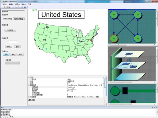
1 Example Realized by Our Tools
Tools for BMRSS are implemented after the previous analysis and design, which
integrate all the functions of the mentioned modules. To demonstrate the application
of the tools, an air-to-air attack and defense scenarios is built including red-side fed-
erates and blue-side federates. As is shown in Fig. 8, blue-side federate includes a
multi-resolution plane fleet and a multi-resolution sense system, while the red-side
federate is composed of a multi-resolution enemy plane fleet. A blue-side federate
represents the low resolution model and a plane fleet represent the middle resolution
model which can disaggregate into several high resolution planes – wing plane, lead
plane and so on. A same structure is applied to the red-side federate.
Blue-side Federate Red-side Federate
Attack
Lead-Enemy
Lead-Plane Plane
Wing-Enemy Wing-Enemy
Wing-Plane1 … Wing-Plane n Radar 1 … Radar m Plane1 … Plane n
Defense Enemy Plane Fleet
Plane Fleet
Sense SystemFig. 8. air-to-air attack and defense
In the simulation process, the blue-side planes search for the invading red-side
plane in the mode of fleet. In this state all the components are running at a low resolu-
tion, since individual entity interacting is not required. When an enemy plane appears
in the field of blue-side represented by a map in Fig. 9, the plane fleet of blue-side
receives a disaggregate order. Then both the plane fleet and the sense system run at a
high resolution, during which the lead plane is responsible for the task of communi-
cating with radar and sending attacking orders to wing planes. The simulation will
end with the destroyed or expelled of red-side plane. To reduce the simulation cost
maximally, components aggregate into low resolution ones. The tools implemented
are proved to be very helpful for component modeling and effective for resolution
controlling.
Fig. 9. Example realized by BMRSS
2 Conclusions
As a result of these efforts, the BOM component has shown effectiveness for solving
many of the problems within large-scale joint simulation exercises which require
multi-resolution modeling. BMRSS proposed in the paper can help the developers to
build reusable component and executable codes, which makes the development con-
venient and flexible. The resolution control mechanism that includes RSC, ADG and
Con BOM makes MRM more accurate and powerful. Dual Engine Simulation archi-
tecture makes it possible for components to interact and maintain consistency inside
federate within IESS.Acknowledgements
This work was supported by the National Key Technology R&D Program under
Grant # 2012BAF15G00.
References:
1. Natrajan, A.: Consistency maintenance in concurrent representations. University of Vir-
ginia(2000)
2. Baohong, L., Kedi, H.: A formal description specification for multi-resolution modeling
(MRM) based on DEVS formalism. : Artificial Intelligence and Simulation. pp. 285-294.
Springer (2005)
3. Bernard, P., Zeigler, Hessam, S., Sarjoughian.: Introduction to DEVS Modeling and
Simulation with JAVA: Developing Component-Based Simulation Models, Arizona Cen-
ter for Integrative Modeling and Simulation, University of Arizona and Arizona State
University, Tucson, Arizona, USA, (2005)
4. Chase, T., Gustavson, P. The Application of Base Object Models (BOMs) for Enabling
Multi-Resolution Modeling. In: 2004 Fall Simulation Interoperability Workshop(2004)
5. Moradi, F., Nordvaller, P., Ayani, R. Simulation model composition using BOMs. In:
10th IEEE International Symposium on Distributed Simulation and Real-Time Applica-
tions, pp. 242-252(2006)
6. Moradi, F. Component-based simulation model development using BOMs and web ser-
vices. In: 1st Asia International Conference on Modeling & Simulation, pp. 238-246
(2007)
7. Junjie Huang., Heming Zhang.: Multi-Granularity Modeling of virtual prototyping in
collaborative product design. In: 12th International Conference on Computer Supported
Cooperative Work in Design, pp.710-715. Xi'an ( 2008)
8. Powell, D.R.: Control of entity interactions in a hierarchical variable resolution simula-
tion. Los Alamos National Lab., NM (United States) (1997)
9. Mei, Y., Ying, C., Jian, H., Peng, Z. Research on atomic component model development
in BOM-based HLA simulation. In: 2nd International Conference on Software Engineer-
ing and Service Science, pp. 905-910 (2011)
10. Gustavson, P., Chase, T. Using XML and BOMS to rapidly compose simulations and
simulation environments. In: Simulation Conference Proceedings, vol. 2, pp. 1467-
1475(2004)
11. Qiang, H., Yong, P., Ming-xin, Z. Parallelization of simulation engine for BOM compo-
nent on multi-core. In: 3rd International Conference on Communication Software and
Networks (ICCSN), pp. 250-254(2011)
12. Xiaocheng, L., Bin, C., Ke, Z., Kedi, H. Execution management of the BOM-based simu-
lation system. In: Asia Simulation Conference-7th International Conference on System
Simulation and Scientific Computing, pp. 287-290(2008)
13. Chunguang, P., Qiang, H., Xiaocheng, L., Xinye, Z. Component Scheduling in the
Distributed Simulation based on BOM. In: Second International Conference on Comput-
er Modeling and Simulation, pp. 98-102(2010)
14. Base Object Models, www.boms.info/You can also read