SYSTEMDESK - EB TRESOS STU- DIO - TARGETLINK
←
→
Page content transcription
If your browser does not render page correctly, please read the page content below

SystemDesk - EB tresos Studio - TargetLink - Workflow Descriptions

SystemDesk - EB tresos Stu-
dio - TargetLink
Workflow Descriptions

Usable with Versions:
dSPACE SystemDesk 4.1
EB tresos Studio 13 or 14
TargetLink 3.4 or TargetLink 3.5 (with patches)

February, 2014

                                                                     1 / 38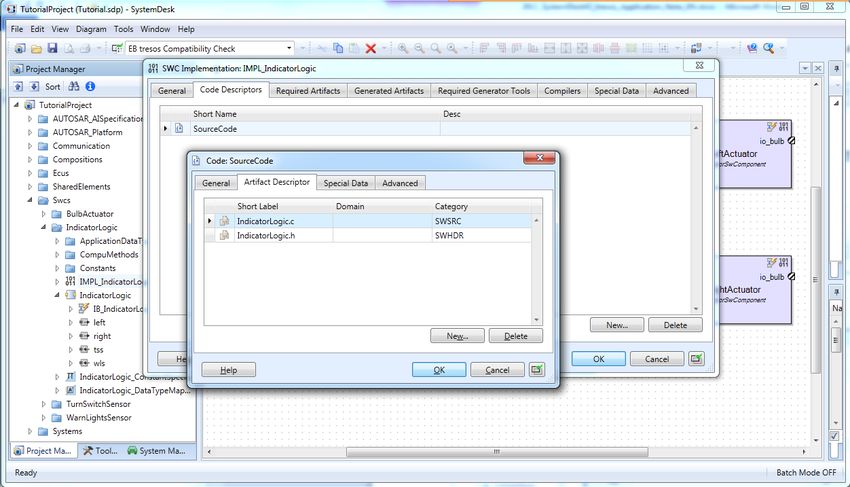
SystemDesk - EB tresos Studio - TargetLink - Workflow Descriptions

Contents
Contents ..................................................................................................................................................2

1 Introduction ..........................................................................................................................................3

2 SystemDesk and EB tresos Studio ....................................................................................................4
   2.1 Overview .........................................................................................................................................4
   2.2 Development of the Architecture ....................................................................................................4
       2.2.1 Step 1: Importing the System or Communication description ...............................................5
       2.2.2 Step 2: Modeling the Software Architecture ..........................................................................5
       2.2.3 Step 3 (optional): Modeling the System .............................................................................. 10
       2.2.4 Step 4: Exporting a System Extract .................................................................................... 11
   2.3 Configuration and Generation of Basic Software......................................................................... 12
       2.3.1 Overview ............................................................................................................................. 12
       2.3.2 Creating a new ECU configuration project ......................................................................... 13
       2.3.3 Importing the System Extract.............................................................................................. 15
       2.3.4 Configure AUTOSAR modules ........................................................................................... 18
       2.3.5 Verify the configuration ....................................................................................................... 22
       2.3.6 Add the communication parts to the basic software ........................................................... 23
       2.3.7 Export service component interfaces ................................................................................. 23

3 Function Development ..................................................................................................................... 24
   3.1 Overview ...................................................................................................................................... 24
   3.2 Exporting a software component from SystemDesk .................................................................... 25
   3.3 Importing a software component in TargetLink ............................................................................ 26
   3.4 AUTOSAR support in TargetLink ................................................................................................. 27
       3.4.1 Frame Model Generation .................................................................................................... 27
       3.4.2 Generation of Application or Implementation Data Types .................................................. 28
       3.4.3 Generation of a Constant Specification Mapping ............................................................... 29
   3.5 Delivering the architecture and the code files .............................................................................. 29

4 Build the ECU target Software ........................................................................................................ 30
   4.1 Preparation of the Build Environment .......................................................................................... 30
   4.2 Building the Software ................................................................................................................... 30

5 Detailed Element Descriptions in SystemDesk ............................................................................. 31
   5.1 Mandatory attributes .................................................................................................................... 31
   5.2 Data Type Mapping ...................................................................................................................... 33
   5.3 Constant Specification Mapping .................................................................................................. 35

6 Restrictions ....................................................................................................................................... 38

2 / 38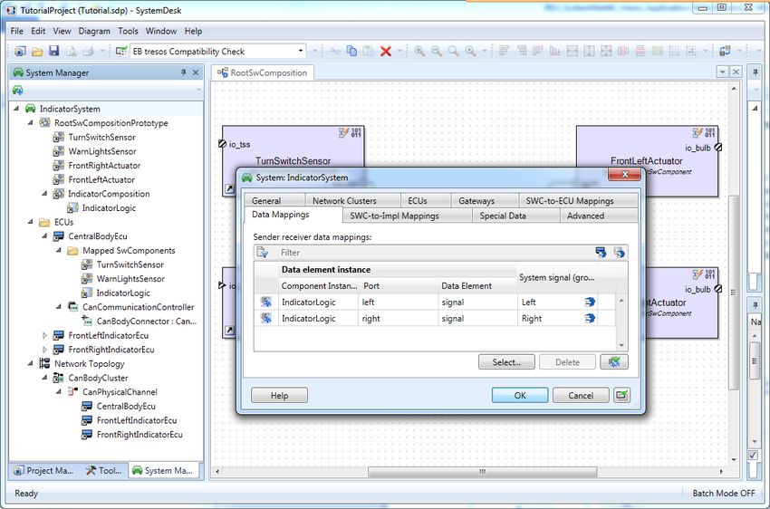
SystemDesk - EB tresos Studio - TargetLink - Workflow Descriptions
1 Introduction
SystemDesk, TargetLink and EB tresos Studio are three AUTOSAR tools which can be used together
in an AUTOSAR tool chain for creating ECU software – SystemDesk for modeling the architecture of
the application software, TargetLink for generating code for the application software, and EB tresos
Studio for configuring and generating the basic software as well as for RTE configuration and genera-
tion. In order to reach executable code for the ECU, the three tools must work well together. This doc-
ument explains in detail how to interconnect the tools and which steps of the workflow should be per-
formed in which tool.
SystemDesk
TargetLink
Modeling environment for
Code generation from Matlab/
AUTOSAR software components,
Simulink/Stateflow
ECUs and networks
EB tresos Studio
ECU basic software
configuration, integration and
validation
Figure 1: AUTOSAR tools described in this document
This document describes the interaction between the three AUTOSAR tools, dSPACE SystemDesk,
dSPACE TargetLink and EB tresos Studio, versions
SystemDesk 4.1
EB tresos Studio 13 or 14
TargetLink 3.4 or 3.5
It is assumed that you are familiar with using these tools, so no further introduction to them is provided
here. Further information on the single tools can be found in the documentation:
SystemDesk 4.x Tutorial
SystemDesk 4.x Guide
SystemDesk 4.x Reference
ContainerManagementDocument
TargetLink AUTOSAR Modeling Guide
EB tresos Studio users guide
This application note first describes the interfaces of the three tools and how to work with them in or-
der to get the ECU target software. Chapter 2 is dedicated to the interface between SystemDesk and
EB tresos Studio. Chapter 3 explains how to integrate TargetLink into the tool chain. And chapter 4
describes how to build the ECU target software. The subsequent chapters give additional help for
specific aspects: Chapter 5 gives a detailed description on how to model specific elements in Sys-
temDesk in order to get a smooth transfer of the data to EB tresos Studio.
3 / 38
SystemDesk - EB tresos Studio - TargetLink - Workflow Descriptions

2 SystemDesk and EB tresos Studio
2.1 Overview
This chapter describes the typical steps which are needed when using SystemDesk and EB tresos
Studio for creating the software of an ECU. Figure 2 gives an overview of the complete workflow. The
first step is to import the system or communication description in SystemDesk which is provided by the
OEM. SystemDesk is then used for modeling the software architecture and the system. For this task, it
can also be necessary to import service interfaces, which need to be exported from EB tresos Studio.
When the architecture and system are complete, they are exported from SystemDesk and imported in
EB tresos Studio. Here, the basic software can be configured and generated, resulting in code files for
the basic software.
This chapter describes the single steps of this workflow. Section 2.2 is dedicated to the steps to be
performed in SystemDesk, Section 2.3 describes the EB tresos Studio parts. Function development
and the interaction between TargetLink and SystemDesk / EB tresos Studio are not addressed in this
chapter. Refer to chapter 3 for this topic.

                               System
                               System or
                                       or
                           Communication
                           Communication (arxml)
                                         (arxml)

               OEM                                        SystemDesk

                                         Service
                                         Service                              Software
                                                                              Software Architecture
                                                                                       Architecture and
                                                                                                     and System:
                                                                                                         System:
                                         Interfaces
                                         Interfaces                           System
                                                                              System Extract
                                                                                     Extract (arxml)
                                                                                             (arxml)
                                         (arxml)
                                         (arxml)

                                                        EB tresos Studio

                                                         Basic
                                                          Basic Software
                                                                Software
                                                             code
                                                             code files
                                                                   files
                                                      (EB
                                                      (EB tresos
                                                           tresos AutoCore)
                                                                  AutoCore)

              Figure 2: Overview of the workflow with SystemDesk and EB tresos Studio

The following sections describe the single steps of this workflow in detail. They also give hints about
how to avoid some errors.

2.2 Development of the Architecture
This section describes those parts of the workflow which are performed in SystemDesk. It is divided
into four main steps from import of the system or communication description to export of the complete
system. In each step, it is described what you should do and why you should do it. For simpler as-
pects, it is also described how to model them. A detailed instruction for modeling the more complex
aspects is given in section 5.

4 / 38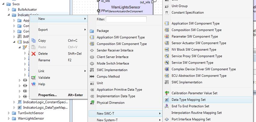
SystemDesk - EB tresos Studio - TargetLink - Workflow Descriptions

2.2.1 Step 1: Importing the System or Communication description
The first step is to import the system or communication description in SystemDesk, using the AU-
TOSAR import. Choose File / Import AUTOSAR.

                      Figure 3: Importing a system or communication description
Select the arxml file, click Open and then select the complete content of the arxml file. When you click
Finish Import, the complete content of the file is imported into SystemDesk. You can see it in the pro-
ject manager.

2.2.2 Step 2: Modeling the Software Architecture
The software architecture is modeled in SystemDesk. Using the AUTOSAR package structure, you
can create software components with internal behaviors and their interconnections. For details about
modeling the software architecture, please refer to the SystemDesk Guide.
If the imported file already contains a composition for your software architecture, you should model
your software architecture inside this composition. Otherwise, you need to create one composition
which contains the complete architecture for your ECU with all software components and their inter-
connections. In the following, this composition will be called the top-level composition.
When modeling your architecture, you should make sure that it is correct and complete. The following
sections describe important aspects for modeling the software architecture.
The modeling guideline takes the later generation phase of the RTE and the basic software into ac-
count. Therefore it is necessary to model the software architecture according to the AUTOSAR strict
schema version (see also section 2.2.2.5).

                        Figure 4: Project with a complete top-level composition

                                                                                                   5 / 38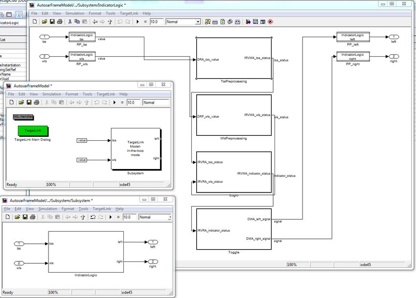
SystemDesk - EB tresos Studio - TargetLink - Workflow Descriptions

2.2.2.1 Service Interfaces
In AUTOSAR, there are some basic software modules that have an interface to the application com-
ponents (for example Dem and EcuM). Such modules are also called service components, because
they make specific services available to the application components. The actual specification of the
service components is always project-dependent. First, you have to configure a module of this kind in
EB tresos Studio, then you can generate the service component description, and finally, you can con-
nect the ports of the service components to the ports of the application components. All these steps
can be performed in EB tresos Studio (see section 2.3.6 ).
You must ensure that the ports of the application components are compatible with the ports of the
service components, as otherwise RTE generation is not possible. This means that the interface de-
scriptions of the services are required during the creation of the software architecture in SystemDesk.
EB tresos Studio therefore lets you export all the interface descriptions of the service components in
the basic software. For further details on the service components and their export in EB tresos Studio,
refer to section 2.3.6.
These interface descriptions can now be imported in SystemDesk, and then be used for the ports of
the application components.

2.2.2.2 Initial Values
For generating the RTE, it is advisable that you define an initial value for each variable data prototype
and parameter data prototype. Examples for variable data prototypes are interrunnable variables or
data elements in sender-receiver interfaces. If the data prototype is accessed, but it does not have a
value yet, the initial value is used instead. For most kinds of variable data prototypes, the initial values
can be defined in their Properties Dialog.

           Figure 5: Defining initial values in the variable data prototype's Properties Dialog
Exceptions are variable/parameter data prototypes defined in interfaces. Initial values for these are
defined separately for each port in its com specs. For each connection between two ports transmitting
a variable/parameter data prototype, the initial value(s) must be defined in either the provide- or the
require-port. If an initial value is defined in both ports, the initial value of the require-port is used.

6 / 38
SystemDesk - EB tresos Studio - TargetLink - Workflow Descriptions

                       Figure 6: Defining initial values in the com spec of a port

2.2.2.3 Application Data Types and Application Constants
With release 4, AUTOSAR distinguishes application data types (ADTs) and implementation data types
(IDTs). ADTs describe data as physical values from an application view, whereas IDTs represent the
same data as internal values and specify the implementation details. IDTs are needed for code gener-
ation in TargetLink and also for RTE generation.

It is not mandatory to use ADTs, but if you do, they need to be mapped to IDTs. For this, you need one
or more data type mapping sets, which can be created in SystemDesk via the context menu of a
package. The data types can be mapped in its Properties Dialog.

                    Figure 7: Mapping of application to implementation data types

                                                                                                7 / 38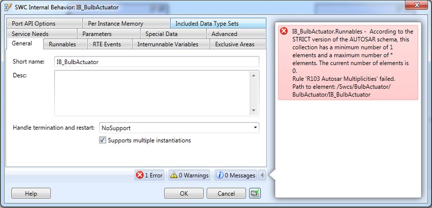
SystemDesk - EB tresos Studio - TargetLink - Workflow Descriptions

You need to create at least one reference to a data type mapping set from each atomic software com-
ponent. All ADTs which are used in a software component need to be mapped to IDTs in one of the
data type mapping sets which are referenced by it. You can use the same mapping for several soft-
ware components or you can create a different mapping for each SWC.

If you use TargetLink, you can also use the Implementation Data Type Creation Wizard for creating
the mappings. Details about how to model the data type mapping in SystemDesk are described in
section 5.2. The usage of TargetLink’s ImplementationDataType Creation Wizard is explained in sec-
tion 3.4.2.

If you use application data types, you might additionally need to create one or more constant specifica-
tion mappings. This is the case if you have application constants in your project. Application constants
describe a physical value, but for RTE generation the corresponding internal values are required. For
this, EB tresos Studio expects a mapping of application constants to implementation constants, which
represent the corresponding internal values. SystemDesk automatically creates application constants
for values of application data types: For example, initial values for data elements typed by an applica-
tion data type are application constants. The mapping can be performed in SystemDesk (see section
5.3 for a detailed instruction) or in TargetLink (see section 3.4.3).

                               Figure 8: Constant specification mapping

2.2.2.4 SWC Implementation
The element SWC implementation describes the implementation details of one internal behavior. For
each internal behavior, you need at least one SWC implementation to be able to generate the RTE in
EB tresos Studio. You can create it from the context menu of an internal behavior.

8 / 38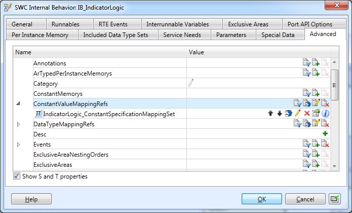
SystemDesk - EB tresos Studio - TargetLink - Workflow Descriptions

                           Figure 9: SWC implementation Properties Dialog
For describing the code files, you need to create a code descriptor on the Code Descriptors Page of
the SWC Implementation Properties dialog. Then, each file is described by one artifact descriptor.
Four properties are used for describing the code file: short label, category, domain and revision labels.

                                    Figure 10: Describing code files
If you use TargetLink for code generation, you do not need to model the SWC implementations by
hand: TargetLink creates them automatically. You only need to reimport the arxml-description of the
software component in SystemDesk after code generation (see chapter 3).

2.2.2.5 Validation and the STRICT schema
While modeling the software architecture, you should use SystemDesk’s validation mechanism. The
validation will assist you in identifying some possible sources of error at this early stage. You can use
the default validation for checking general consistency constraints and rules defined by AUTOSAR, or

                                                                                                    9 / 38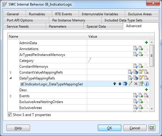
SystemDesk - EB tresos Studio - TargetLink - Workflow Descriptions

you can use the predefined validation rule set EB tresos Compatibility Check. When activated, Sys-
temDesk additionally checks special issues regarding the exchange with EB tresos Studio. For exam-
ple, it is important to see already in SystemDesk whether your project is complete or which model
parts are still missing. The AUTOSAR strict schema defines many elements which need to be present
in a complete project. The validation according to the EB tresos Compatibility Check validates the
project according to the strict schema, and additionally checks for some further mandatory elements.
Like this, you can detect already in SystemDesk whether your project is complete and can be pro-
cessed in EB tresos Studio. However, validation in SystemDesk can identify most but not all potential
problems that might be reported by EB tresos Studio in a later step. Also note that the validation
checks for conformance to the strict schema according to AUTOSAR R4.1.1. If you export your model
in a different schema version, it can happen that some elements are mandatory in this version which
are optional in AR 4.1.1, and therefore the validation does not indicate these missing elements.

You can activate the EB tresos Compatibility Check in SystemDesk’s toolbar. After that, you can vali-
date elements from their context menu in the Project Manager or directly from their Properties dialog.

              Figure 11: Activating the EB tresos Compatibility Check validation rule set

                   Figure 12: Validation of an Internal Behavior without a runnable

2.2.3 Step 3 (optional): Modeling the System
Whether you need to model a system depends on what you have imported in the first step. If you have
imported a complete system including a mapping of data elements to system signals, you do not need
to do anything. Otherwise, it is recommended to model the system in SystemDesk.
SystemDesk offers the System Manager for this task. The most important parts the system consists of
are the root software composition, the ECU(s) and the imported network topology, a mapping of soft-
ware components to ECUs and a mapping of data elements to system signals. Refer to the Sys-
temDesk Guide for an introduction on how to model the system.

10 / 38
SystemDesk - EB tresos Studio - TargetLink - Workflow Descriptions
Figure 13: Modeling the System
2.2.4 Step 4: Exporting a System Extract
There are several possibilities how to export your architecture for EB tresos Studio. It is only important
that the exported arxml-file contains all parts of the system which are associated with your ECU. This
comprises the complete software architecture and the AR element representing the system with
- a reference to your ECU
- a reference to your top-level composition with your software architecture
- a mapping of your software components to the ECU
- a mapping of data elements to bus messages.
The simplest way to export it is to create a system extract. You can do this via the context menu of the
system. Before exporting, you can choose the ECU(s) which shall be contained in the system extract.
The resulting file can then be imported in EB tresos Studio.
Figure 14: Creating a system extract
11 / 38SystemDesk - EB tresos Studio - TargetLink - Workflow Descriptions
Figure 15: Selecting the ECUs for a system extract
2.3 Configuration and Generation of Basic Software
This section describes those parts of the workflow in detail which have to be performed in EB tresos
Studio. The so called “workflow” guides you through this configuration job which includes the following
main issues:
creating a new ECU configuration project (chapter 2.3.2)
importing the system extract created by SystemDesk (chapter 2.3.3)
mapping of the application events onto Os tasks of the basic software (chapter 2.3.4.6)
generating the basic software and the RTE
2.3.1 Overview
The system extract which has been created with SystemDesk is the base for configuring the AU-
TOSAR Basic Software (EB tresos AutoCore). It contains information about the software components
and their runnables, ports, interfaces and so on. Following the AUTOSAR methodology this system
extract is imported into EB tresos Studio.
The configuration of the EB tresos AutoCore in EB tresos Studio is done in 3 major steps. These steps
are (see also Figure 16):
1. Create ECU configuration project in EB tresos Studio
2. Configure AUTOSAR basic software (EB tresos AutoCore Generic)
a. Import system extract
b. Complete configuration of basic software with support of wizards and assistance dia-
logs
3. Generate basic software and build target code
Figure 16: Workflow in EB tresos Studio
The following subchapters contain a detailed description how to carry out the different steps. To simpli-
fy the configuration of the basic software EB tresos Studio provides a special view, the so called work-
flows view which contains a step-by-step instruction to guide you through the configuration (see Figure
17). The workflows view also contains helpful information to each step. For more details on the work-
flows view please refer to the user documentation of EB tresos Studio.
12 / 38SystemDesk - EB tresos Studio - TargetLink - Workflow Descriptions
Figure 17: The workflows view in EB tresos Studio
In this application note the workflow Setup an initial project is used to explain how to get a valid ECU
basic software configuration. This workflow is available with your EB tresos Studio/AutoCore installa-
tion. The basic software used in this workflow contains the following modules (see also Figure 18):
Basic Software Mode Manager (BswM)
Diagnostics event Manager (Dem)
Development error tracer (Det)
Ecu State Manager (EcuM)
Micro controller unit driver (Mcu – stub module if EB tresos WinCore is used)
Operating system (Os)
Runtime Environment (Rte)
Figure 18: Basic Software modules used in this example.
2.3.2 Creating a new ECU configuration project
The first step is the creation of a new ECU configuration project. Just follow the instructions within the
workflows view to initially setup your project (section “Create new project (from template)” in Figure
19).
13 / 38SystemDesk - EB tresos Studio - TargetLink - Workflow Descriptions
Figure 19: Instructions to create an ECU configuration project.
The basic template project which shall be imported can be found in the EB tresos Studio installation
directory (see Figure 20).
Figure 20: Location of basic template project in the EB tresos Studio installation directory.
Don’t miss to select the option “Copy projects into workflows folder” for the project import:
14 / 38SystemDesk - EB tresos Studio - TargetLink - Workflow Descriptions
Figure 21: Dialog to import a project in EB tresos Studio
After completing the working step “Create new project (from template)” your project appears like this
(in this case the project has been renamed to “dSPACE_EB”):
Figure 22: The Project Exporer shows the new project
2.3.3 Importing the System Extract
The configuration of the Basic Software starts with the import of the system extract which has been
created with SystemDesk before. To do the import, an AUTOSAR system description importer has to
be configured in EB tresos Studio. The workflows view again gives detailed information how to pro-
ceed (Figure 23).
15 / 38SystemDesk - EB tresos Studio - TargetLink - Workflow Descriptions
Figure 23: Instructions to import the system extract into the project.
The settings that have to be made for the importer are displayed in Figure 24 - Figure 27.
You can provide an arbitrary name for the importer. In Figure 24 the name has been chosen equally to
the file name of the import file.
Figure 24: Importer configuration for the import of the system extract.
In the configuration tab All Models location of the input file has to be specified. In our case it is the
system extract which has been exported out of SystemDesk. It is recommendable to first copy this into
the project folder in the workspace because this file is always project specific. Then select the system
and an ECU instance (Figure 25).
16 / 38SystemDesk - EB tresos Studio - TargetLink - Workflow Descriptions
Figure 25: Importer configuration: selection of system and Ecu instance.
In the configuration tab System Model Import the import options have to be set (Figure 26).
Figure 26: Importer configuration: system model settings.
Note that the ECU configuration import is disabled for this workflow step. How to include the commu-
nication data is described in chapter 2.3.6 (configuration tab ECU Configuration Import, Figure 27).
17 / 38SystemDesk - EB tresos Studio - TargetLink - Workflow Descriptions
Figure 27: Importer configuration: disable the ECU configuration import.
Run the importer to import the data of the system extract into the internal system data base of EB
tresos Studio. After the import you should receive no errors and no warnings. The import of the system
extract is now completed.
2.3.4 Configure AUTOSAR modules
The configuration of the AUTOSAR basic software modules applies for the modules which are listed in
chapter 2.3.2. The workflows view again displays the necessary steps (Figure 28). To each configura-
tion step the help view below the instruction list provides useful information.
18 / 38SystemDesk - EB tresos Studio - TargetLink - Workflow Descriptions
Figure 28: Instructions to configure the basic software modules.
2.3.4.1 Configure Det Module
Since there is no software component that reports to the Det module this step can be skipped.
2.3.4.2 Configure Os Module
The system extract contains software components and their runnable entities. These runnable entities
must be mapped to Os tasks. The tasks have to be created in the Os configuration. Double click on
the action step “Configure Os module” in the workflows view to open the editor for the Os configuration
and add the tasks RteTime_Task, RteEvent_Task and RteCat2_Task (Figure 29). For more infor-
mation refer to the help view within the workflows view or to the user manual of EB tresos AutoCore.
Figure 29: New tasks within the Os task configuration.
19 / 38SystemDesk - EB tresos Studio - TargetLink - Workflow Descriptions
2.3.4.3 Configure BswM Module
No action is necessary to configure the BswM module.
2.3.4.4 Calculate Dem, NvM and EcuM service needs
The basic software modules are not independent of each other. These dependencies are resolved by
the service needs calculator which for example automatically adds the init functions of the different
basic software modules to the EcuM (EcuM initializes the Ecu) or adds the required Dem events to the
Dem configuration. To run the service needs calculator double click the action step in the workflows
view. The service needs are now calculated and the configurations of the affected modules are auto-
matically updated.
2.3.4.5 Update service component and BSWM descriptions
The Service Component and BSWM Description Updater generates and imports the basic software
module description (BSWMD) of all modules.
The update of the BSWMD is a prerequisite for the configuration of the main-function-to-task mapping
and of the configuration of the BSW exclusive area in the RTE. Moreover, the Service Component and
BSWM Description Updater also generates and imports the service component descriptions for ser-
vice modules (e.g. Det). After this step, the service components are available and can be connected to
the application software components.
To run the Service Component and BSWM Description Updater, double-click the action step Update
service component and BSWM descriptions in the Workflows view.
2.3.4.6 Configure RTE module
The configuration of the RTE is done with a special RTE editor. To launch this editor double click the
action step Configure Rte module within the workflow and then select Rte Editor (Figure 30).
Figure 30: Launching the RTE Editor.
To generate RTE code as well as the BSW scheduler code the item Rte Generator Output in the tab
General has to be set to Full (Figure 31).
Figure 31: Rte Generator Output Settings and Os counter settings in the Rte Editor.
20 / 38SystemDesk - EB tresos Studio - TargetLink - Workflow Descriptions
The RTE needs a reference to an Os counter. The basic template which is used in this example al-
ready provides the software counter Rte_Counter. Verify that this counter is selected in the General
tab of the Rte editor (see also Figure 31).
Now the RTE Events have to be mapped to the Os tasks. To do the mapping, open the tab Event
Mapping in the Rte Editor. In the upper table the events, their executable entities, SWC instances and
timing requirements are listed (Figure 32).
Figure 32: List of events that have to be mapped.
In the middle of this tab a task can be selected on which events may be mapped. The lower table lists
the events that have already been mapped to the selected task. To map the events listed in Figure 32
select the previously configured task RteTime_Task (Figure 33). After that select the events with 10.0
ms period in the upper table und click the map-button (Figure 34). The selected events are now
mapped to the task RteTime_Task.
Figure 33: Selection of the task to which events may be mapped.
21 / 38SystemDesk - EB tresos Studio - TargetLink - Workflow Descriptions
Figure 34: Mapping of events to a task.
Now map the two non-periodic events (DataReceivedEvent) to the RteEvent_Task.
The event TssCyclic20ms is not yet mapped. This event is of category CAT2 which means it may not
terminate. Therefore this event is mapped to an own task: RteCat2_Task.
The RTE editor can be closed now.
2.3.4.7 Calculate Os and Com service needs
It is recommended that you run the Service Needs Calculator again to add the Os and Com objects
required by the RTE module to the Os configuration. Since this requires a consistent RTE configura-
tion, this step is recommended after you have completed the configuration of the RTE. Therefore dou-
ble click the action step Calculate Os and Com service needs.
2.3.4.8 Update service component and BSWM descriptions
The last steps have changed the ECU configuration, on which the BSWMD depends. Thus, it is rec-
ommended to update the basic software module description again. Therefore double click the action
step Update service component and BSWM descriptions.
2.3.5 Verify the configuration
The configuration of the basic software modules is now completed. To verify the configuration and
check for configuration errors press the button verify selected project (Figure 35).
22 / 38SystemDesk - EB tresos Studio - TargetLink - Workflow Descriptions
Figure 35: Verify the configuration.
After successful verification the code can be generated for the basic software modules. To do so click
the generate button in the tools bar (Figure 36).
The generated code can be found in the folder:
/workspace/dSPACE_EB/output/generated
Figure 36: Generate code for the basic software modules.
2.3.6 Add the communication parts to the basic software
To add the communication modules and to import the communication data, switch to the workflow
“CAN stack” or “FlexRay stack” as shown in Figure 37. Then follow the workflow instructions for CAN
or FlexRay in the same way as we did in the previous chapters for the workflow Setup an initial pro-
ject.
Figure 37 Workflows for communication
2.3.7 Export service component interfaces
As described in section 2.2.2.1 the software component description of the basic software can be gen-
erated. Figure 38 illustrates how to generate the SW-CD.
Figure 38 Generate SW-CD of service modules
The output files can be found in the folder:
/workspace/dSPACE_EB/output/generated/swcd/
The interfaces can be found in the file(s) _swc_interface.arxml. In the current example, no
basic software services are configured. Therefore these files are not generated.
23 / 38SystemDesk - EB tresos Studio - TargetLink - Workflow Descriptions
To be able to generate a SW-CD of a basic software module, this module has to be configured in EB
tresos Studio. Especially the parameter “Enable Rte Usage” has to be enabled to switch on the port
generation. The generation of the SW-CD is even possible if there are errors in the configuration pro-
ject.
The generated interfaces are imported into SystemDesk to ensure that the application SW-C uses
interfaces which are compatible to the basic software.
So the overall workflow is as follows:
Pre-configure the basic software in EB tresos Studio and generate the SW-CD of the basic
software services
Import these service interfaces into SystemDesk and create a complete system description
Import the system description into EB tresos Studio and finalize the configuration of the RTE
and the basic software
3 Function Development
3.1 Overview
This chapter describes how to integrate the function development in the workflow described in chapter
2.
If you use hand-programmed code, you need to make sure that it fits to the internal behavior described
in the software architecture, and that it is compliant to AUTOSAR. The code files are then handed over
to be integrated in the EB tresos AutoCore Build Environment.
If you use TargetLink for code generation, you can use the architecture which is defined in Sys-
temDesk. Figure 39 shows an overview of the interaction of TargetLink with SystemDesk and EB
tresos Studio. It extends the workflow described in section SystemDesk and EB tresos Studio2.
The first step is to export a software component from SystemDesk as arxml (or SWC container) and
import it in a TargetLink data dictionary. You can then reuse the data types, interfaces, ports, data
accesses, runnables etc. for your behavior model. You can also use TargetLink to extend the imported
architecture. TargetLink offers for example a simple possibility to generate implementation data types
from application data types, and it creates a constant specification mapping when needed. When the
behavior model is complete, you can generate the code for the software component.
Now you can optionally hand back the description of the software component to SystemDesk. This
makes sense especially if you have extended the architecture for example by implementation data
types or if you want to simulate your ECU using VEOS. In this case, the software component has to be
returned as an arxml file to the software architecture in SystemDesk. Whether transferring the archi-
tecture or not, the code files have to be handed over to the EB tresos AutoCore Build Environment for
building the ECU code.
In the following, the single steps are described in more detail. Detailed information about the data ex-
change between SystemDesk and TargetLink can be found in the Container Management Document.
24 / 38SystemDesk - EB tresos Studio - TargetLink - Workflow Descriptions
SystemDesk
Service-
Service- Software
Software architecture
architecture Software
Software Software
Software
Interfaces
Interfaces and
and system:
system: component
component component
component
(arxml)
(arxml) SystemExtract
SystemExtract (arxml)
(arxml) (arxml)
(arxml) (arxml)
(arxml)
EB tresos Studio TargetLink
Basic software Application
code files code files
(EB tresos AutoCore)
EB tresos AutoCore
build environment
ECU
Figure 39: Overview of the interfaces between TargetLink, SystemDesk and EB tresos Studio
3.2 Exporting a software component from SystemDesk
The first step is to export the software component from SystemDesk for which the behavior shall be
modeled in TargetLink. Before you do this, it is advisable to use SystemDesk’s validation: SystemDesk
4.1 supports the complete AUTOSAR schema. TargetLink, on the other hand, has some limitations
regarding specific AUTOSAR features. Therefore, before exporting software components from Sys-
temDesk, you should validate your project for compatibility with TargetLink. The validation indicates
many of TargetLink’s limitations directly in SystemDesk, so that you can adapt your project according-
ly. For using the TargetLink validation, select the applicable validation rule set in the tool bar and then
validate your project.
Figure 40: Selecting a TargetLink validation rule set
Then you can do the export from SystemDesk. TargetLink focusses mostly on single, atomic software
components. Therefore, you should export each SWC from SystemDesk separately. The process of
im- and export is simplified by the SWC container management functionality, which bundles all neces-
sary files and takes care of synchronizing them according to a specified workflow. For exporting a
software component as container from SystemDesk, you first need to specify which element is export-
ed to which arxml file in the Container File Explorer.
25 / 38SystemDesk - EB tresos Studio - TargetLink - Workflow Descriptions
Figure 41: The Container File Explorer
Then, you can export the software component via its context menu: choose Container Management /
Export Container. A dialog shows which arxml files will be added to the container. After a confirmation,
the export is performed.
More details about file assignment and the container manager can be found in the SystemDesk Guide
and the Container Management Document.
3.3 Importing a software component in TargetLink
For importing the software component in TargetLink, open the AUTOSAR data dictionary in which you
want to import the software component. If you create a new data dictionary, make sure that you create
it according to the AUTOSAR template.
Figure 42: Creating a new data dictionary according to the AUTOSAR template
When you have opened the data dictionary, select File / Import / From Container and select the con-
tainer with the software component you have exported from SystemDesk. Confirm the settings and
TargetLink will import the software component.
26 / 38SystemDesk - EB tresos Studio - TargetLink - Workflow Descriptions
Figure 43: Excerpt from a data dictionary with an imported SWC
3.4 AUTOSAR support in TargetLink
TargetLink offers several functionalities which simplify the behavior modeling according to AUTOSAR.
The following sections describe the most important functionalities. A more detailed description can be
found in the TargetLink AUTOSAR Modeling Guide.
3.4.1 Frame Model Generation
TargetLink offers a functionality to generate an AUTOSAR frame model (skeleton model) based on the
AUTOSAR-related specifications of a software component in the TargetLink Data Dictionary (DD). The
AUTOSAR frame model generation simplifies designing a Simulink/TargetLink model for a software
component significantly, because the TargetLink user does not need to deal with all AUTOSAR details
but can focus on filling in the frame model with the actual control algorithm. To generate an AUTOSAR
frame model, select the respective software component object in the TargetLink Data Dictionary and
choose the AUTOSAR Tools/Generate Frame Model context menu entry. TargetLink will then create a
new model from scratch which contains blocks for the runnables, AUTOSAR ports, data access points,
etc. for that particular software component. The user can now fill in the content of the runnables with
TargetLink blocks, drag already prepared subsystems from a Simulink library into the runnables or e.g.
use TargetLink Custom Code blocks to call already existing, non-AUTOSAR legacy C code functions.
In any case, getting to a first design of the SWC in TargetLink is made rather easy.
27 / 38SystemDesk - EB tresos Studio - TargetLink - Workflow Descriptions
Figure 44: A generated frame model
The frame generation functionality in TargetLink does not only support model generation from scratch,
but also the automatic update of an existing model of a SWC. For that purpose, select the respective
SWC object in the Data Dictionary and choose the AUTOSAR Tools/Update AUTOSAR Model context
menu entry. TargetLink will then not only update the model but also generate an update report con-
taining hyperlinks to navigate to the individual AUTOSAR-related blocks and the respective DD ob-
jects. Moreover, the AUTOSAR frame model functionality in TargetLink provides a huge number of
hooks to adapt the frame generation to individual company-specific needs.
3.4.2 Generation of Application or Implementation Data Types
If you use application data types in your software architecture, you can use TargetLink to generate
implementation data types (IDTs) and data type mapping sets. These describe internal values and
specify implementation details like a base type. IDTs are needed for code and RTE generation and
appear in the generated code.
In the context menu of a software component, select AUTOSAR Tools / ImplementationDataType
Creation Wizard. In the upper part of the dialog, you can select the package in which newly generated
IDTs will be saved or you can specify the name for a new package.
The lower left part of the dialog shows all ADTs which are not mapped to IDTs in the data type map-
ping set of the selected software component. If no data type mapping set exists, all ADTs are shown
and a new data type mapping set is created.
In the lower right part of the dialog, you can see a suggestion for an IDT for the selected ADT. You can
either map the ADT to an existing IDT or base type, or you can generate a new IDT by specifying a
new name and a base type. In this case, the scaling and the ranges of the IDT are taken over from the
ADT. Click Apply to save the settings for the selected ADT.
In a similar way, ADTs can be generated from IDTs using the Applicaton Data Type Creation wizard, if
this is required.
28 / 38SystemDesk - EB tresos Studio - TargetLink - Workflow Descriptions
Figure 45: Mapping ADTs to IDTs
Note that each atomic software component needs a reference to a data type mapping set. If you use
TargetLink to generate them, you will receive an own mapping set for each software component. If you
want to use the same mapping set for several software components, you should create it in Sys-
temDesk and reference it from each software component. You can then generate or map the IDTs in
TargetLink using the wizard.
3.4.3 Generation of a Constant Specification Mapping
As described in section 2.2.2.3, constants specifying physical values need to be transformed into in-
ternal values to be used in the code for the software components and for RTE generation. For this, EB
tresos Studio expects a mapping of such application constants to implementation constants via a con-
stant specification mapping set.
TargetLink generates such a mapping automatically, if the mapping does not already exist. For each
application constant, it uses the compu method (scaling) attached to its data type to compute the in-
ternal value, saves it as an implementation constant and maps both constants in a constant specifica-
tion mapping set. If no compu method exists, an identical mapping is assumed.
Like for data type mappings, TargetLink creates one constant specification mapping set for each soft-
ware component. If you want to use the same mapping for several software components, you can
create the mapping set and reference it from the SWCs in SystemDesk, and then let TargetLink auto-
matically create the implementation constants and the mappings.
3.5 Delivering the architecture and the code files
When you have finished the implementation and code generation, you can hand over the generated
code files to the EB tresos AutoCore build environment for the final build. Additionally, you can hand
back the arxml-description of the software component and the code files to SystemDesk. It makes
especially sense to do this if you want to use SystemDesk and VEOS for simulating your ECU, or if
you have extended the software architecture, for example by one of the following:
Implementation data types and a data type mapping
A constant specification mapping
Parts of the internal behavior of a SWC
You can again use the container manager to return the changes in the software architecture to Sys-
temDesk. The code files are also automatically contained in the container.
29 / 38SystemDesk - EB tresos Studio - TargetLink - Workflow Descriptions
Moreover, TargetLink generates an SWC implementation element for each software component,
which specifies the code files and implementation details. EB tresos Studio also needs this element in
your software architecture. If you do not return the software architecture to SystemDesk, you need to
model it by hand.
For exporting a container for one SWC from TargetLink, choose Export Container from the context
menu of a software component. You can import it in SystemDesk via the context menu of your project.
Figure 46: Importing a container in SystemDesk
4 Build the ECU target Software
The basic software generated in chapter 2.3 and the application software according to chapter (3.5)
can now be compiled and linked using the EB tresos AutoCore build environment. More details can be
found in the EB tresos AutoCore documentation. This workflow step can be divided into two steps:
4.1 Preparation of the Build Environment
The installation path of your EB tresos Studio installation has to be stated. Open the file /workspace//util/launch.bat
and set the variable TRESOS_BASE to the installation path of EB tresos Studio.
The location of your application files, generated from TargetLink has to be stated. Open the file
/workspace//util/common.mak
and add extend the path setting of the variable CC_FILES_TO_BUILD.
If you are using the EB tresos WinCore, nothing else has to be done. If you generate the code for an
embedded target, the compiler has to be configured. Open the file
/workspace//util/__Makefile.mak>
and set the variables TOOLCHAIN and COMPILER. Then open the file
/workspace//util/___cfg.mak>
and set the variable TOOLPATH_COMPILER.
4.2 Building the Software
The complete software, including the basic software and the application can now be built. Ensure that
EB tresos Studio is closed when you start the build process for the first time. Then do the following
steps:
Execute
/workspace//util/launch.bat
30 / 38SystemDesk - EB tresos Studio - TargetLink - Workflow Descriptions
Type “make depend” in the DOS shell
Type “make” in the DOS shell
After compilation, the executable file can be found within the folder:
/workspace//output/bin
The executable file can now be loaded to the target with your debugger tool chain.
5 Detailed Element Descriptions in SystemDesk
This section describes how to model specific aspects in SystemDesk, which were discussed in section
2.2. While you can find reasons for when and why using these elements in section 2.2, this section
gives an instruction on how to model them.
Section 5.1 describes attributes of frequently used elements which are mandatory according to the
strict schema. You should therefore model them in SystemDesk, since most of them will be needed in
EB tresos Studio later on. Section 5.2 describes how to do a data type mapping in SystemDesk, and
section 5.3 describes how to model a constant specification mapping.
5.1 Mandatory attributes
This section gives detailed information about attributes of some frequently used elements in Sys-
temDesk which are mandatory according to the strict schema and which should therefore be
present when importing a project in EB tresos Studio. You can use it as a reference when de-
signing your architecture in SystemDesk. This document gives information about mandatory el-
ements, but it does not explain them. You can find a description and an explanation of the attrib-
utes in the AUTOSAR templates. A short explanation is also available as a tooltip in the ad-
vanced tab of each dialog.
Note that a checkbox has three possible values in SystemDesk. If such an attribute is mandatory, it
must be true or false:
Not defined
True
False
This table lists the mandatory attributes for frequently used elements.
Element Mandatory attributes
Application Primitive Data Type SW data def props: SW calibration access
Application Array Data Type Element type ref
Max number of elements
Application Record Data Type At least one record element
Implementation data type Dependent on category.
For category VALUE: Base type
SWC Internal Behavior Supports multiple instantiations
Handle termination and restart
At least one runnable entity
31 / 38SystemDesk - EB tresos Studio - TargetLink - Workflow Descriptions
SWC Implementation SWC internal behavior
SW version
Vendor ID
Resource consumption
Programming language
Runnable Entity Can be invoked concurrently
Minimum start interval
Symbol
Sender Receiver Interface At least one variable data prototype
Is service
Client Server Interface At least one operation
Is service
Mode declaration group At least one mode
Initial mode ref
Mode switch interface Mode group
Is service
Variable data prototype / pa- Data type
rameter data prototype
Argument data prototype Data type
Direction
Data constraint Only for AUTOSAR R4.0, not anymore with AUTOSAR R4.1:
If physical constraints are specified: reference to a unit
(Advanced page DataConstrRules / DataConstrRule / PhysCon-
strs / UnitRef
If the constraint is for an enumeration (compu method of catego-
ry texttable), the constraints must be given as internal constraints
in the form of values.
Provided/Required Port Proto- Interface
type
NonQueued Sender ComSpecs Init value
Handle out of range
Uses end to end protection
NonQueued Receiver Alive timeout
ComSpecs
Handle out of range
Handle timeout type
Enable update
Handle never received
Uses end to end protection
32 / 38SystemDesk - EB tresos Studio - TargetLink - Workflow Descriptions
Queued Sender ComSpecs Uses end to end protection
Handle out of range
Queued Receiver ComSpecs Queue length
Uses end to end protection
Handle out of range
Mode Switch Sender Queue length
ComSpecs
Server ComSpecs Queue length
Constant Specification UnitRef (Advanced page ValueSpec / SwValueCont / UnitRef)
(Application constant)
ECU Wake up over bus supported
Sleep mode supported
At least one CommController. Depending on the type of the
CommController, further attributes are required. SystemDesk‘s
strict schema validation can be used to find out which attributes.
System System version
5.2 Data Type Mapping
In order to model the data type mapping in SystemDesk, create a new data type mapping set via the
context menu of a package: New / New SWC-T / Data Type Mapping Set.
Figure 47: Creating a new data type mapping set
In its Properties dialog, you can create new mappings on the Data Type Mapping page. Each mapping
refers to one ADT and one IDT, which must be compatible, i.e. the category and the size.
33 / 38SystemDesk - EB tresos Studio - TargetLink - Workflow Descriptions
Figure 48: Mapping application data types to implementation data types or base types
Once you have created one or more data type mapping sets, you need to create a reference from
each internal behavior to the mapping(s) which shall be used in this context. You can do this on the
Advanced page of the internal behavior’s Properties dialog, in the field DataTypeMappingRefs. You
can reference the same mapping set from several internal behaviors, or you can create an own map-
ping set for each internal behavior.
Figure 49: Referencing a data type mapping set from an internal behavior
34 / 38SystemDesk - EB tresos Studio - TargetLink - Workflow Descriptions
5.3 Constant Specification Mapping
Before giving a detailed description about how to map application constants to implementation con-
stants, the following figure explains what needs to be done. It is assumed that you have mapped your
application data types to implementation data types. Now, for each application constant – that is, a
constant created for a data prototype which is typed by an application data type – an implementation
constant needs to be created. As the two constants shall be mapped later on, they need to be compat-
ible. SystemDesk assists you in achieving this by letting you choose an implementation data type for
the constant, and then generates the internal structure of the constant according to the data type. The
easiest way is to choose the implementation data type to which the application data type is mapped
(Figure 50).
Application Implementation
Mapped to
Data Type Data Type
Typed by
Data Prototype Create according to
Created for
Application Implementation
Map to
Constant Constant
Figure 50: Overview over Constant Specification Mapping
For mapping application constants to implementation constants in SystemDesk, you need to do the
following. For each application constant, create a new constant specification, and open its Properties
dialog. Then click the icon in the field Value specification.
Figure 51: Empty Constant Specification
SystemDesk now opens a dialog for you to select a data type according to which the internal structure
of the constant will be created. This is where you define whether the constant specification is an appli-
cation or an implementation constant. Select the implementation data type to which the application
data type of the application constant is mapped.
35 / 38SystemDesk - EB tresos Studio - TargetLink - Workflow Descriptions
Figure 52: Selecting a data type for a constant
Click OK, and a second dialog opens. Here, you can enter the value of the constant in the field Scalar.
Note that the attribute ShortLabel does not change the short name of the constant (which is visible in
the project manager), but the label of the value specification, which can only be seen on the Advanced
page.
Figure 53: Entering the value of a constant
Now the implementation constant is complete.
Figure 54: Implementation constant with value 0
36 / 38SystemDesk - EB tresos Studio - TargetLink - Workflow Descriptions
When you have created implementation constants for all your application constants, the next step is to
map the constants to each other. For this, you have to create constant specification mapping sets,
which contain the mapping of the constants, and you have to reference the mapping sets from the
internal behaviors of the software components. AUTOSAR is rather flexible here: Each internal behav-
ior can reference one or more mapping sets, and each mapping set may be used in one or more inter-
nal behaviors. The only constraint is that for each internal behavior, each application constant may
only be mapped once to an implementation constant, such that the mapping is unambiguous. This
means that you can decide whether you want to create only one mapping set and reference it from all
software components, whether you want to create one specific mapping set for each software compo-
nent, or whether you even want to split the mapping sets. It is for example possible to create one
mapping set for all constants which are shared between several SWCs, and an additional mapping set
for each SWC containing the constants only used in this context.
You can create a new mapping set via New / New SWC-T / Constant Specification Mapping Set in the
context menu of a package. In its Properties dialog, go to the Advanced page. In the Mappings-list,
create a new ConstantSpecificationMapping by clicking . There you can reference the application
and the implementation constant.
Figure 55: Mapping application to implementation constants
To reference the mapping set from an internal behavior, open the internal behavior’s Properties dialog
and go to the advanced page again. The mapping sets are referenced from ConstantValue-
MappingRefs. For adding a new reference, click .
Figure 56: Referencing constant specification mappings from an internal behavior
37 / 38You can also read