Tunicate Swarm Algorithm-Neural Network for Adaptive Power System Stabilizer Parameter
←
→
Page content transcription
If your browser does not render page correctly, please read the page content below
P-ISSN 2586-9000
                                                                                                E-ISSN 2586-9027
                    Homepage : https://tci-thaijo.org/index.php/SciTechAsia             Science & Technology Asia

                    Vol. 26 No.3 July - September 2021                                              Page: [50-63]

                                        Original research article

        Tunicate Swarm Algorithm-Neural
        Network for Adaptive Power System
              Stabilizer Parameter
  Widi Aribowo*, Supari Muslim, Bambang Suprianto, Subuh Isnur Haryudo, Joko

                  Department of Electrical Engineering, Faculty of Engineering,
                    Universitas Negeri Surabaya, Surabaya 60243, Indonesia

              Received 19 August 2020; Received in revised form 3 December 2020
                 Accepted 15 January 2021; Available online 6 September 2021

ABSTRACT
       Tunicate Swarm Algorithm (TSA) is a metaheuristic method that imitates the life of the
tunicate. It occurs during navigation and foraging using jet propulsion and swarm behavior. A
feed-forward neural network ( FFNN) is a neural network that is often used, and applied.
computational methods have been widely used to optimize FFNN weights in order to produce
better output. This paper proposes a compound algorithm based on a tunicate swarm
algorithm to optimize an FFNN. It is applied to power system stabilizers. The proposed
method is compared with other algorithm methods such as the feed-forward (FFNN), cascade
forward backpropagation (CFBNN), focused time delay (FTDNN), and distributed time delay
(DTDNN). The proposed method has the ability to improve the output of FFNN methods. The
proposed method has the average ability to reduce the overshoot of the speed by 35.17% and
the undershoot of the rotor angle by 15. 36% . In addition, the proposed method has better
capabilities than the comparison method. The results of the experiment show that the use of
the submitted algorithm has preferable adaptability and performance than the other methods.
Keywords: Feed-forward neural network; Metaheuristic; Neural network; Power system
stabilizer; Tunicate Swarm Algorithm

1. Introduction                                           operation is to keep the synchronous
      Progress     in     economic     and                generator running at its work point and able
technological development is followed by                  to meet load demands according to the
demand for electric system requirements.                  available capacity. Synchronous machines
The electrical network is a collection of                 do not handly go down of swing under
non-linear and complex systems that is                    regular forms. If a machine swing tends to
influenced by the increase in load changes.               increase or decrease, synchronizing induces
The main key in a reliable power system                   it to perform normally. A condition often

*Corresponding author: widiaribowo@unesa.ac.id                                doi: 10.14456/scitechasia.2021.46
W. Aribowo et al. | Science & Technology Asia | Vol.26 No.3 July - September 2021
occurs when the synchronization from the Search Algorithm [17-20], Fuzzy [20-22]
generator is less reliable and has a little and neural networks [23-26].
influence on the system, causing a generator Research on the power system
to lose synchronization. Meanwhile, stabilizer is a popular area. Although many
changes in load are followed by an studies have presented research in the power
imbalance between supply and demand. system stabilizer area, there is still plenty of
This results in the generator having to try to room to explore for the best performance.
stay in sync to adapt to new operating This paper has main contributions, namely:
conditions. Some disturbances often occur 1) Application of the newest and promising
in the form of major disturbances such as method of metaheuristics, namely the
disconnection of the generator from the Tunicate Swarm Algorithm. The method
system, network outages, or small and was presented by Kaur et al in April 2020.
random load changes that occur in regular In a study conducted by Kaur et al, it was
conditions. Oscillations often follow found that the TSA method had the best
disturbances. Oscillations can be damped by performance compared to the Spotted
leading to new operating conditions. This is Hyena Optimizer (SHO) method, Gray Wolf
called a stable system. Optimizer (GWO), Particle Swarm
Oscillations that often occur and have Optimization (PSO), Multiverse Optimizer
a large impact are low frequencies in the (MVO), Sine Cosine Algorithm (SCA),
0.2-2 Hz range [1]. The equipment used in Gravitational Search Algorithm (GSA),
solving the sway stability obstacle is the Genetic Algorithm (GA), and Emperor
power system stabilizer (PSS). The PSS is Penguin Optimizer (EPO) [27]. Based on
able to increase damping so that it can research by Kaur et al, this paper is using
reform the achievement of the power the TSA method to optimize the feed-
system. forward neural network method. The
Conventional PSS has a design using proposed method is called TSA-FFNN. The
control theory. Power system modeling is proposed method is used to adjust the power
assumed to be linear around nominal system stabilizer.
operation. The PSS variable is assumed and 2) The focus of this research is to measure
assigned to get the best performance. In the output performance of the rotor speed
fact, the power system has a nonlinear and angle in a single machine.
character and operation that varies over a 3) Accuracy and potential are presented by
wide range. This is a weakness of conducting in-depth comparisons using
conventional PSS which cannot provide several methods, namely feed-forward
optimal performance with complex (FFNN), cascade forward backpropagation
problems. This is exacerbated by the (CFBNN), focus time delay (FTDNN), and
configuration of an electrical system that distributed delay time (DTDNN).
turns frequently. It also requires attention in
the PSS adjustment in maintaining its best 2. Materials and Methods
performance [2]. 2.1 Tunicate Swarm Algorithm
In recent years, methods using artificial Tunicate Swarm Algorithm is an
intelligence have begun to be used with the algorithm that duplicates tunicate colonies.
aim of optimizing PSS variables such as This animal is a group of marine animals
particle swarm optimization (PSO) [3-5], which live on docks, rocks or the bottom of
taboo search [6], genetic algorithm [7-9], boats. To most people, they look like tiny
Biogeography-Based Optimization [10-12], blobs of color. The tunicate can be seen
bat algorithm [13-15], world cup from afar because it is capable of producing
optimization algorithm [16], Harmony bright blue-green light or bioluminescence.
51W. Aribowo et al. | Science & Technology Asia | Vol.26 No.3 July - September 2021
Tunicates have two ends that have where Vmin and Vmax reflect the beginning
different functions; an open end, which is and lower speeds to create social contact.
used as a propulsion such as jet propulsion
The variables Vmin and Vmax have work
using atrial siphons, and a closed end.
Tunicates move by relying on fluid bursts values 1 and 4.
[ 27] . This burst is so powerful that it can 2.1.2 Shifting to the position of the
move tunicates vertically in the ocean. This best tunicate
animal has a shape in the millimeter scale. If conflict between tunicates can be
Tunicates have the expertise to find food avoided, the tunicates will approach the best
sources in the sea when there is no food tunicates.
source information. Tunicates have the
!!!!!!!" !!" !!!!!!"
readiness to recognize food. This is called X fs (n) = X s - rand × X p (n) , (2.5)
jet propulsion and swarm intelligence
Mathematical modeling of the first
where the distance between the food source
behavior of the tunicates, namely the !!!"
propulsion of the jet, must meet three and tunicate is X fs in Eq. (2.5), n is the
conditions: to prevent disputes between current iteration. The location of the food
!!" !!!!!!"
tunicates, to shift the potential tunicate source is X s . Vector X p (n) shows the
locatoin, and to close on the potential
tunicate. On the other hand, the swarm location of the tunicate. A disordered grade
behavior has a function to update the in space [0, 1] is rand .
existence of other seekers in order to find
the best optimal solution. 2.1.3 Assemble with the best tunicate
Tunicate can update its position
2.1.1 Keep away the conflict among towards the best tunicate. It is related to the
tunicate position of food source
To dodge the clash between tunicates, !!" !" !!!"
the new search agent position calculation ìï X s + T × X fs , if rand ³ 0.5,
(T) can be modeled as follows in Eq. (2.1). x(t ) = í !!" !" !!!" (2.6)
!!" ïî X s - T × X fs , if rand < 0.5,
!" H
T = !!" , (2.1) where x(t ) in Eq. (2.6) is the updated
M
!!" !!" position of tunicate with respect to the
H = r2 + r3 - W , (2.2) !!"
!!" position of food source X s .
W = 2 × r1 , (2.3)
!!" 2.1.4 Swarm behavior
where gravity force is H in Eq. (2.1) and Optimal solutions are the best kept
Eq. (2.2). The movement of water advection and other tunicates positions are updated by
!!"
in the deep sea is W in Eq. (2.2) and Eq. searching for the best tunicate positions.
The tunicate crowd behavior can be
(2.3). r1 ,r2 and r3 are disorder grade that
!" formulated as follows in Eq. (2.7).
have a range [0, 1]. S in Eq. (2.4) is the !!!!!!" !!!!!!!!!!"
!!" !!!!!!" X p (n) + X p (n + 1)
colony strength between the tunicates. M X p ( n) = . (2.7)
describes the social compels between search 2 + r1
agents. The tunicate position will determine the last
!" position in a random area. The key points of
S = êëVmin + r1 (Vmax - Vmin ) úû , (2.4) the turnicate swarm algorithm are:
52W. Aribowo et al. | Science & Technology Asia | Vol.26 No.3 July - September 2021
!" !!" !!"
- Parameters T ,H and W guard and Output is the sum of the weighted and
support a specified search space and biased inputs that have passed through the
transfer function. The Formula Processing
avoid conflict between tunicates.
can be seen in Eq. (2.8) and Eq. (2.9).
- It is hoped that the exploration and
Output is processed by going through the
exploitation phase will get a better value
!" !!" !!" next layer weight. This process is repeated
by using vector variations T ,H and W . until it matches the algorithm specified.
- The group behavior of the TSA
n
algorithm can be observed from jet Oi (t ) = åW jn I n (t ) + b1 , (2.8)
propulsion and tunicate colony behavior. j =1
1
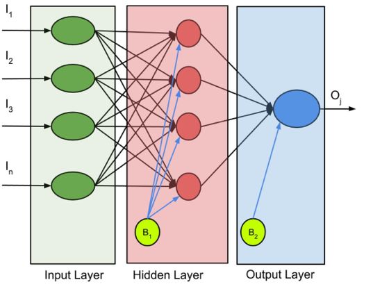
2.2 Feed forward neural networks O j (t ) = f (Oi (t )) = . (2.9)
Neural Networks are designs that try 1 + expOi
to replicate several of the fundamental
information execution methods proposed in Neural network weighting optimization is to
the brain. The advantages of neural get the best weight to achieve a higher
networks are high-level computing classification in terms of accuracy.
applications, the ability to learn and The mean square error (mse) is taken
generalize (generalization is to produce the to assess the fallacy. The MSE formula can
appropriate output for input), ability for be seen in Eq. (2.10).
non-linear problems, and adaptability [28]. n
ANN has an advanced neural network and a MSE = å (target i - Oi ) 2 . (2.10)
feedback neural network. Feed-forward i =1
networks have the characteristics of a
2.3 Power system stabilizer
simple network structure and are easy to
The power system stabilizer (PSS)
implement [29]. The network is developed
has the function of adding attenuation to the
from several neurons in each layer which
system to avoid electromechanical
are connected by weighting intermediaries.
oscillations caused by minor disturbances. A
Neurons from related units in the previous
PSS in general has three important
layer, the weighted input which is summed
components, namely gain, washout and
by the refractive unit is passed to a single
phase compensation. The block unit of a
neuron. The function of bias is to adapt the
PSS can be seen in Fig. 2. In a conventional
input to a practical and possible range. The
PSS, gain is still used and requires good
Model of FFNN is illustrated in Fig. 1.
resetting capability when operating
conditions change.
Fig. 2. PSS Block Diagram.
The conventional PSS consists of a K pss
gain unit related to a high-pass filter with a
time constant T w and a lead-lag
Fig. 1. Conceptual model of a feed-forward compensated phase unit with time T1 and
neural network. T2 . PSS output ( Vs ) in Eq. (2.11) is the
input added to the excited system. The input
53W. Aribowo et al. | Science & Technology Asia | Vol.26 No.3 July - September 2021
of PSS represents the synchronous speed voltage of the AVR. The rotor speed and the
deviation from the system Dwi . rotor angle are w and d . The transient and
steady state internal voltage of the armature
sT w 1 + sT1 are Eq' and E fd .
Vs = K pss × × × Dwi (2.11)
1 + sT w 1 + sT2 In the mechanical loop, K A is DC
gain and TA is time constant of the AVR.
3. Results and Discussion
The generator is modeled in the K D and 2H = M indicate the damping
Heffron-Phillips model. The model can be factor and rotor inertia. Tdo' is the direct axis
seen in Fig. 3. It includes K1-K6, well-
open circuit time constant. K A is DC gain.
known Heffron-Phillips variables. Tm is
TA is time constant of the AVR.
input torque and Vref is the reference
Fig. 3. Heffron–Phillips block diagram for SMIB power system [30].
Fig. 4 is the assembly of TSA with speed and rotor angle. The methods used for
FFNN for setting PSS in a single machine. comparison are FFNN, CFBNN, FTDNN,
In this paper, the training data is using the and DTDNN. In this paper, the neural
output speed and rotor angle of the system network setting is using 4 hidden layers.
as input for FFNN. At the start of the The number of iterations is limited to 1000
processing in the TSA session, the random in order to avoid overfitting. Meanwhile, the
weighting values were derived from the training method used Levenberg Marquardt
FFNN. The random weight value is which has advantages in speed and stability.
optimized using the TSA method. The The loading variation is also used to
output will be the strength weight for examine the capability of the submitted
FFNN. algorithm. In this study, the load variation
Verification and validation are uses light loads (20%), medium loads
employed to assess the achievement of the (60%), and loads close to full load (90%).
submitted method. TSA-FFNN was The first step is knowing the variables
measured by comparing the results of the required for the TSA method. This is to get
54W. Aribowo et al. | Science & Technology Asia | Vol.26 No.3 July - September 2021
the optimal value. The results from the TSA with 100 iterations, this study is adding the
will be used to obtain the best FFNN population data below the data, namely
variable. Based on research from Kaur et al, using a population of 10. This is used to test
which used 30 and 50 tunicate populations the convergence of the curve.
Fig. 4. The TSA-FFNN Flowchart.
The results are shown in Fig. 5. TSA parameter has been obtained it is used
Details of the use of the TSA method can be for training the FFNN. Table 2 shows
seen in Table 1. The best value is obtained complete details of the TSA parameters
with a tunicate population of 50. Once the used.
55W. Aribowo et al. | Science & Technology Asia | Vol.26 No.3 July - September 2021
Fig. 5. Convergence Curve Of Tunicate for TSA-FFNN.
Table 1. Parameter values for various response to the speed and rotor angle can be
population TSA. seen in Fig. 6 and Fig. 7. Detailed results
Population Settling Best from case 1 can be seen in Table 3. In Table
Tunicate Rise Time Time (s) Peak Fitness
10 68.5930 76.0741 1.1495 0.3922 3, the proposed method has overshoot of a
30 7.1213 34.4710 0.7333 0.2255 speed response value with 0.1660. The
50 28.3982 96.2053 0.6075 0.1777 value is the best performance comparing
with other methods. The second-best value
Table 2. Parameter of TSA. is the application of conventional methods
Algorithm Parameter Value which has a value with 0.1988. The TSA-
Upper And Lower Limit [-0.5,0.5] FFNN method has 16.5% better
Maximum number of performance than conventional methods.
TSA
iterations 100
Meanwhile, the TSA-FFNN method has the
Population of Tunicate 50
best performance of undershoot rotor angle.
This value is -1.5772. It is followed by the
The loading variation is used to test use of conventional methods with -1.6763.
the ability of the PSS modeling that applies The lowest value is obtained by the
the TSA-FFNN method. The case 1 is to DTDNN method with -1.9408.
give 20% loading to the system. The
56W. Aribowo et al. | Science & Technology Asia | Vol.26 No.3 July - September 2021
Fig. 6. Speed with 20 % Load.
Fig. 7. Rotor Angle with 20 % Load.
57W. Aribowo et al. | Science & Technology Asia | Vol.26 No.3 July - September 2021
Table 3. PSS With 20 % of Load.
Speed Response Rotor Angle Response
Methods Under Settling Settling Time
Shoot Over Shoot Rise Time (s) Time (s) Under Shoot Rise Time (s) (s)
Conventional -0.4012 0.1988 0.0054 110.7963 -1.6763 0.5191 145.2667
FFNN -0.4811 0.3011 0.1720 107.2049 -1.9292 1.5021 147.0082
CFBNN -0.4797 0.2997 0.1732 106.9809 -1.9301 1.6084 147.1597
FTDNN -0.4316 0.2562 0.1519 109.1226 -1.8221 1.1943 148.1122
DTDNN -0.4818 0.2986 0.1817 107.1667 -1.9408 1.8207 146.6075
TSA-FFNN -0.3473 0.1660 0.2305 117.8808 -1.5772 1.1475 150.2386
Experiment 2 is to give 60% loading to the the TSA-FFNN method. The waves are
system. Fig. 8 and Fig. 9 are the results of sloping compared to other methods. Details
experiment 2. It can be seen in waves from of case 2 can be seen in Table 4.
Fig. 8. Speed with 60 % Load.
Fig. 9. Rotor angle with 60 % Load.
58W. Aribowo et al. | Science & Technology Asia | Vol.26 No.3 July - September 2021
Table 4. PSS With 60% of Load.
Speed Response Rotor Angle Response
Methods Under Settling Time Time
Under Shoot Time Settling(s)
Shoot Over Shoot Rise Time (s) (s) Rise (s)
Conventional -0.6457 0.2984 0.0054 108.6542 -2.5016 0.1665 143.9857
FFNN -0.6693 0.3794 0.2533 107.9757 -2.7096 2.1331 146.9509
CFBNN -0.6549 0.3724 0.2600 107.9826 -2.6885 2.2132 147.3345
FTDNN -0.6113 0.3260 0.2232 110.0022 -2.5499 1.9220 148.5396
DTDNN -0.6583 0.3814 0.2772 108.0680 -2.6869 2.3795 147.1166
TSA-FFNN -0.5602 0.2456 0.3364 115.2298 -2.3203 1.9272 149.3650
In Table 4, the lowest value for FFNN method has the best value on the
overshoot of the speed response, 0.3814, is undershoot of rotor angle. This value is
obtained by the DTDNN method. The best 16.77% better than the conventional method
value is achieved by the proposed method which is second best.
with 0.2456 and followed by the In case 3 with 90% loading assigned
conventional method with 0.2984. The to the system, the measurement is to
method proposed in case study 2 has determine the system response when given a
17.69% better ability than the conventional load nearby to 100% full load. The results
method. Meanwhile, the lowest value for the of the speed and rotor angle can be seen in
undershoot rotor angle belongs to the FFNN Fig. 10 and Fig. 11.
method. The value is -2,7096. The TSA-
Fig. 10. Speed with 90 % Load.
59W. Aribowo et al. | Science & Technology Asia | Vol.26 No.3 July - September 2021
Fig. 11. Rotor angle with 90 % Load.
Table 5. PSS With 90% of Load.
Speed Response Rotor Angle Response
Methods Settling Time
Settling Time (s)
Under Shoot Over Shoot Rise Time (s) (s) Under Shoot Rise Time (s)
Conventional -0.8171 0.3768 0.0086 106.6638 -3.1336 0.1750 140.7572
FFNN -0.8121 0.4186 0.3052 107.4492 -3.2253 2.4394 145.0699
CFBNN -0.8009 0.4133 0.3137 107.4591 -3.1943 2.5386 145.4819
FTDNN -0.7742 0.3757 0.2684 108.8626 -3.0737 2.1785 146.2465
DTDNN -0.8211 0.4354 0.3343 107.3687 -3.2207 2.7557 145.0275
TSA-FFNN -0.7226 0.3055 0.4030 112.4465 -2.8748 2.2282 146.2570
Table 5 shows the results for case 3. 4. Conclusion
The worst value for overshoot of the speed This paper aims to comprehensively
response is in DTDNN with 0.4354. The review the tunicate swarm algorithm (TSA)
best value is from the TSA-FFNN, which is literature to improve the performance of a
followed by conventional methods. The feed-forward neural network ( FFNN) and
TSA-FFNN method has 18.92% better compare its performance. Its objective is to
ability than conventional methods. acquire the best completion for oscillation
Meanwhile, the worst value for undershoot attenuation in the power system by testing
of the rotor angle is in the FFNN method in a single machine. The proposed method
with -3.2253. The best score is obtained by has better results than the comparison
the TSA-FFNN method followed by the method in the load test of 20% , 60% and
FTDNN method. The TSA-FFNN method 90% . In this study, the application of the
has 6.5% better ability than the FTDNN TSA method used to improve the
method performance of FFNN has the benefit of
increasing the ability of FFNN. It can be
seen that the value of the overshoot speed
by FFNN in case study 1 decreased by
60W. Aribowo et al. | Science & Technology Asia | Vol.26 No.3 July - September 2021
44. 67% , case study 2 decreased by about power systems using tabu search
35. 27% , and case study 3 decreased by algorithm. Comput. Electr. Eng
about 26.59% . Meanwhile, the value of the 2002;28:527-45.
undershoot rotor angle by FFNN in case
[7] Kharrazi A. Tuning of power system
study 1 decreased by about 20. 84% , case
stabilizer in Single Machine Infinite Bus
study 2 decreased by about 14. 36% , and (SMIB) using genetic algorithm and
case study 3 decreased by about 10.87% . In Power Factory Modal Analysis.
addition, the proposed method has good Australasian Universities Power
adaptability with load changes. The Engineering Conference (AUPEC),
weakness of the proposed method is that the Wollongong, NSW 2015;1-6.
experiment is using a simple system. So, the
proposed method needs to be tested on a [8] Jebali M, Kahouli O, and Abdallah HH.
more complex system and non-linear issues Power system stabilizer parameters
to determine its performance further. optimization using genetic algorithm. 5th
International Conference on Systems and
Control (ICSC), Marrakesh 2016;78-83.
References
[1] Rogers G, Power System Oscillations: [9] Lokman HH, Moghavvemi M, Haider
Springer Science & Business Media; AFA, Muttaqi KM, Velappa GG.
2012. Optimization of power system stabilizers
using participation factor and genetic
[2] Ekinci S, Demiroren A. Modeling, algorithm. International Journal of
simulation and optimal design of power Electrical Power & Energy Systems
system stabilizers using ABC algorithm. 2014;55;668-679. https://doi.org/10.10-
Turk. J. Elec. Eng. & Comp. Sci., 16/j.ijepes.2013.10.026.
2016;24: 1532-46.
[10] Gholinezhad J, Ebadian M and
[3] Wang D, Ma N, We M, and Liu Y. Aghaebrahimi MR. Coordinated design
Parameters tuning of power system of PSS and SSSC damping controller
stabilizer PSS4B using hybrid particle considering time delays using
swarm optimization algorithm. Int Trans biogeography-based optimization
Electr Energ Syst 2018;28:e2598. algorithm. 30th International Power
https://doi.org/10.1002/etep.2598. System Conference (PSC), Tehran
2015;1-7.
[4] Jagadeesh P and Veerraju MS. Particle
swarm optimization based power system [11] Wang Z, Zuo J, Qiu W, Zou W, Fan M.
stabilizer for SMIB system. International Application of Biogeography-Based
Conference on Emerging Trends in Optimization for Tuning Multimachine
Engineering, Technology and Science Power System Stabilizer Parameters. 3rd
(ICETETS), Pudukkottai, 2016;1-6. International Conference on Advanced
Electronic Materials, Computers and
[5] Soni PB, Saxena A and Gupta V. A Software Engineering (AEMCSE),
Minimax Polynomial Approximation Shenzhen, China 2020;787-93.
Objective Function Approach for
Optimal Design of Power System [12] Kasilingam, G, Pasupuleti J, Bharatiraja,
Stabilizer by Embedding Particle Swarm C, Adedayo Y. Single Machine
Optimization. TELKOMNIKA connected Infinite Bus system tuning
Indonesian Journal of Electrical coordination control using
Engineering 2015;14(2); 191-8. Biogeography: Based Optimization
algorithm. FME Transactions, 2019;
[6] Abido MA, Abdel-Magid YL, 47(3):502-10.
Eigenvalue assignments in multimachine
61W. Aribowo et al. | Science & Technology Asia | Vol.26 No.3 July - September 2021
[13] Sambariya DK, Prasad R, Robust tuning machine power systems. Int J Electr
of power system stabilizer for small Power Energy Syst 2014;54:425-31.
signal stability enhancement using
metaheuristic bat algorithm. [22] Ghasemi A, Shayeghi H, Alkhatib H.
International Journal of Electrical Power Robust design of multimachine power
& Energy Systems 2014;61:229-38. system stabilizers using fuzzy
gravitational search algorithm. Int J
[14] Ali ES. Optimization of Power System Electr Power Energy Syst 2013;51:190-
Stabilizers using BAT search algorithm, 200.
International Journal of Electrical Power
& Energy Systems 2014;61:683-90. [23] Rana MJ, Shahriar MS, Shafiullah M.
Levenberg–Marquardt neural network to
[15] Chaib L, ani Choucha A, Arif S. Optimal estimate UPFC-coordinated PSS
design and tuning of novel fractional parameters to enhance power system
order PID power system stabilizer using stability. Neural Comput & Applic
a new metaheuristic Bat algorithm, Ain 2019;31:1237-48.
Shams Engineering Journal
2017;8(2):113-25. [24] Masrob MA, Rahman MA, George GH.
Design of a neural network based power
[16] Madadi A, Razmjooy N, Ramezani M. system stabilizer in reduced order power
Robust Control of Power System system. IEEE 30th Canadian Conference
Stabilizer Using World Cup on Electrical and Computer Engineering
Optimization Algorithm. International (CCECE), Windsor, ON, 2017;1-6.
Journal of Information, Security and
Systems Management 2016;5(1):519-26. [25] Farahani M, Ganjefar S. An online
trained fuzzy neural network controller
[17] Sambariya DK, Prasad R. Optimal to improve stability of power systems,
Tuning of Fuzzy Logic Power System Neurocomputing 2015;162:245-55.
Stabilizer Using Harmony Search
Algorithm. Int. J. Fuzzy Syst 2015;17: [26] Ansari JA, Memon AP, Shah MA.
457-70. Probabilistic Feedforward Neural
Network Based Power System Stabilizer
[18] Hameed KA, Palani S. Robust Design of for Excitation Control System of
Power System Stabilizer using Harmony Synchronous Generator 2015;8(2):70-4.
Search Algorithm, Automatika
2014;55(2):162-9. [27] Kaur S, Awasthi LK., Sangal AL,
Dhiman G. Tunicate Swarm Algorithm:
[19] Jonglak P, Ngamroo I. Adaptive Power A new bio-inspired based metaheuristic
System Stabilizer Design Using Optimal paradigm for global optimization,
Support Vector Machines Based on Engineering Applications of Artificial
Harmony Search Algorithm, Electric Intelligence 2020;90:103541.
Power Components and Systems
2014;42(5):439-52. [28] Aribowo W, Muslim S, munoto,
Suprianto B, Kartini UT, Asto
[20] Bhati PS, Gupta R. Robust fuzzy logic Buditjahjanto IGP. Tuning of Power
power system stabilizer based on System Stabilizer Using Cascade
evolution and learning. Int J Electr Forward Backpropagation. 2020 Third
Power Energy Syst 2013;53:357-66. International Conference on Vocational
Education and Electrical Engineering
[21] Saoudi K, Harmas MN. Enhanced design (ICVEE), Surabaya, Indonesia, 2020;1-
of an indirect adaptive fuzzy sliding 5.
mode power system stabilizer for multi-
62W. Aribowo et al. | Science & Technology Asia | Vol.26 No.3 July - September 2021
[29] Xue Y, Tang T, Liu AX. Large-Scale [30] Aribowo W. An Adaptive Power System
Feedforward Neural Network Stabilizer Based On Focused Time Delay
Optimization by a Self-Adaptive Neural Network. Jurnal Teknosains,
Strategy and Parameter Based Particle 2018;7(1):67-73.
Swarm Optimization. in IEEE Access
2019;7:52473-83.
63You can also read