Optical Wiggle Tester - Operating Instructions
←
→
Page content transcription
If your browser does not render page correctly, please read the page content below
Optical Wiggle
Tester
Operating Instructions
Optical Wiggle Tester – instruction manual v1.1 June 09
Ktizo Consulting
518 Norwich Road, Ipswich, IP1 6JR. UK
Phone: +44 750 200 4611
email: sales@ktizo.co.uk
web: www.ktizo.co.uk
-2-
Copyright 2009 Ktizo Consulting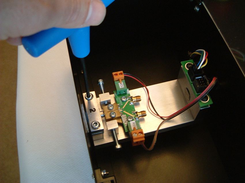
Optical Wiggle Tester – instruction manual v1.1 June 09
Contents
Contents.........................................................................................................................3
Glossary of Terms...........................................................................................................4
Introduction....................................................................................................................6
General Overview...........................................................................................................7
Software Overview.........................................................................................................9
Starting the software..................................................................................................9
Main control panel.....................................................................................................9
Status Panel..............................................................................................................10
Current Program Panel.............................................................................................11
Comments Panel......................................................................................................11
Wiggle Test Results Panel.........................................................................................12
ROSA Calibration......................................................................................................13
Motor Calibration.....................................................................................................15
Manual Motor Control.............................................................................................16
ROSA Testing................................................................................................................17
Fitting the ROSA in the OWT....................................................................................17
Testing......................................................................................................................20
Patchcord Calibration Methods ..............................................................................22
Saving Data...............................................................................................................24
Loading and editing programs..................................................................................25
Adjusting Settings.....................................................................................................26
Technical Specifications...............................................................................................29
Power Supply............................................................................................................29
System Requirements..............................................................................................29
System Communications..........................................................................................29
Physical Dimensions.................................................................................................29
Environmental Specifications...................................................................................29
Optical Wiggle Testing..............................................................................................29
File outputs...............................................................................................................30
For models with auxiliary power supplies:...............................................................30
For models with an auxiliary SFP slot:......................................................................30
Ordering Information...................................................................................................32
-3-
Copyright 2009 Ktizo Consulting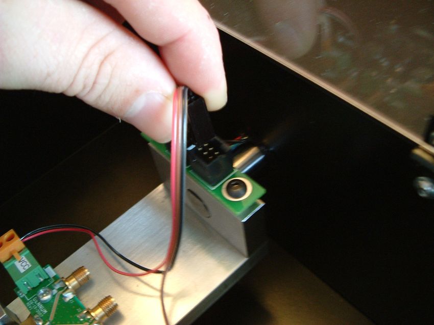
Optical Wiggle Tester – instruction manual v1.1 June 09
Glossary of Terms
ADC Analogue to Digital Converter
DUT Device Under Test
OWT Optical Wiggle Tester
ROSA Receiver Optical Sub-Assembly
TOSA Transmitter Optical Sub-Assembly
SFP Small Form-factor Pluggable transceiver
-4-
Copyright 2009 Ktizo Consulting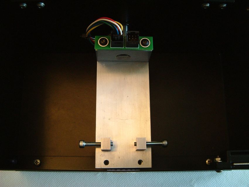
Optical Wiggle Tester – instruction manual v1.1 June 09
Safety Considerations
Users should read the complete instruction manual to familiarise
themselves with the operation of the OWT before attempting to
operate it.
Power Supplies
For OWT’s with an external supply, the voltage of the external supply should be 10-
14V DC (12V Nominal). Exceeding the supply voltage limit may damage the OWT and
will invalidate the warranty.
Positioning the OWT
Only use the OWT on a solid, level surface. e.g. a lab bench.
Ensure the overhang of the OWT is approximately 75mm from the edge. There are
rubber feet positioned approximately 100mm away from the front face of the OWT.
Do not situate the OWT any further forward than these rubber feet, or it may
become unstable.
Top Cover Interlock
The OWT will not function unless the top cover is in the fully down position. If during
a test the top cover is lifted the test will immediately stop and the DUT will stop
rotating.
Emergency Stop Button
The emergency stop button is located on the top side of the OWT. If a situation
arises that requires an immediate stop to the test press the button. The test will
immediately stop and the DUT will stop rotating. To reset the button to allow further
testing, turn the button to release it.
Environmental
Do not attempt to use the OWT in an abnormally hot or humid environment, or in
proximity to explosive gas, vapour or dust.
Servicing
Do not remove any covers from the OWT without express permission of Ktizo
Consulting. Doing so will invalidate both calibration and warranty. There are no user-
serviceable parts inside the OWT. Refer all servicing to Ktizo-approved personnel. Do
not use the OWT if it appears damaged.
-5-
Copyright 2009 Ktizo Consulting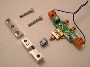
Optical Wiggle Tester – instruction manual v1.1 June 09
Introduction
Optical fibre technology is everywhere. It has enabled the explosive growth of on-
line entertainment and business in the last decade.
One of the greatest challenges facing designers of optical fibre
systems is aligning the tiny fibres with each other. This is
particularly difficult in connectorised systems where fibres may
be mated and de-mated repeatedly.
The challenge is especially great when the fibre is “wiggled”
around. This can happen during installation, or when cabling is
disturbed. In a poorly designed system, several dB of light power
can be lost. This can be enough for an optical system to fail.
Cisco Systems Inc. defined a standard which has been widely adopted throughout
the industry.1 It applies to SFP and other similar optical platforms.
In short, it states that a load should be applied to the patchcord while the DUT is
rotated through 360° at a speed of 4 rpm. The test should be conducted with no
load, with 0.25lb load and with 0.5lb load. Throughout the test, the optical loss in the
system should not exceed 1dB.
Ktizo's Optical Wiggle Tester is a complete turn-key solution to optical wiggle testing.
It conforms to Cisco's specification but is also flexible enough to allow more
thorough testing to help investigate potential alignment problems.
The Optical Wiggle Tester provides a reliable, consistent and easy-to-use way to
analyse wiggle test performance.
The Optical Wiggle Tester is highly configurable and can be used with all types of
optical transceiver modules, TOSAs and ROSAs.
1 Cisco internal document EDCS-287599
-6-
Copyright 2009 Ktizo Consulting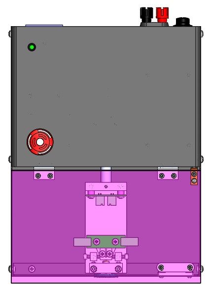
Optical Wiggle Tester – instruction manual v1.1 June 09
General Overview
Top View
Power Indicator
LED
Emergency Stop
Switch
Magnetic
Top Cover Catch
Rear View
Power
Switch
Fuse
PC Communication Port
Power Supply Sockets
(12V DC)
-7-
Copyright 2009 Ktizo Consulting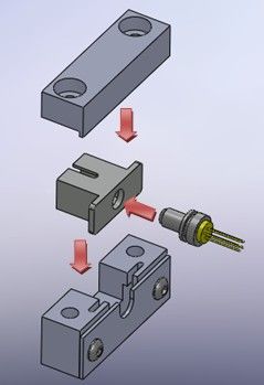
Optical Wiggle Tester – instruction manual v1.1 June 09
Front View
Optical Connector Port
-8-
Copyright 2009 Ktizo Consulting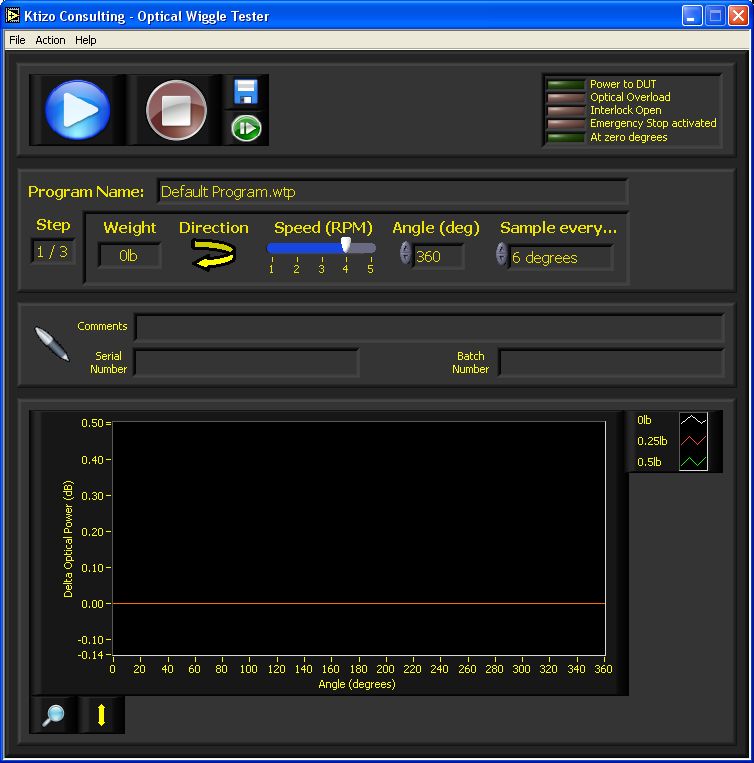
Optical Wiggle Tester – instruction manual v1.1 June 09
Software Overview
Starting the software
The software is loaded by double-clicking the icon.
The splash-screen loads first, followed by the rest of the application. The splash
screen shows the current software version and date.
Main control panel Find zero
Stop Save data degrees
Menu Bar
Status panel
Current Program
Start Panel
Comments
panel
Wiggle Test
results panel
-9-
Copyright 2009 Ktizo Consulting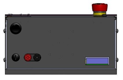
Optical Wiggle Tester – instruction manual v1.1 June 09
Start Button – pressing this button starts the Wiggle Test program that is
currently loaded.
Stop Button – pressing this button at any time during a test run will abort
the test run.
Save Data Button – If this button is pressed, the current data will be saved.
A raw data file is saved, and also an image of the wiggle test results graph.
Find Zero Degrees Button – If this button is pressed, the tester will
automatically find its zero-degrees position, ready to start a new test run.
This is useful particularly when a test run is stopped half-way through for
some reason.
Status Panel
This set of indicators is updated during test runs and when the tester is at idle.
Power to DUT – This is lit when electrical power is applied to the DUT
Optical Overload – This indicator is only used in systems that measure ROSA optical
power. It is lit when the current produced by the ROSA RSSI is too high for the
tester’s ADC to measure accurately. If this indicator lights up, either reduce the
optical power, or contact Ktizo for more information on altering the ADC range.
Interlock Open – This is lit if the clear lid is opened. If it is lit during a test run, the
motor will be automatically stopped, and the test run will be aborted.
Emergency Stop Activated - This is lit if the emergency stop button is pressed. If it is
lit during a test run, the motor will be automatically stopped, and the test run will be
aborted.
At Zero Degrees – This is lit when the tester is at its zero degrees position.
- 10 -
Copyright 2009 Ktizo ConsultingOptical Wiggle Tester – instruction manual v1.1 June 09
Current Program Panel
Program Name – This indicates the name of the current program.
Step – This indicates how far through the program the tester currently is. For
example, 1/3 shows the program has 3 steps, and step 1 is currently running or is
ready to run.
Weight, Direction, Speed, Angle and Sample every… all refer to the current step in
the program.
Weight – This is the weight that should be applied to the fibre.
Direction – This is the direction of rotation of the DUT.
Speed – This is the speed of rotation of the DUT.
Angle – This is the angle through which the DUT will turn.
Sample every… - This shows how often power samples are measured as the
DUT rotates.
Comments Panel
These three boxes are provided to help keep track of test data. Entering data in them
in is entirely optional. This data is used as the basis for the filename to save test data
when the Save Data Button is pressed.
The following characters cannot be used because they interfere with the way the
operating system handles filenames: / \ ? % * : | " < > .
- 11 -
Copyright 2009 Ktizo ConsultingOptical Wiggle Tester – instruction manual v1.1 June 09
Wiggle Test Results Panel
Results
Key
graph
Zoom Change Y-Axis
Results Graph – This is where test results are displayed.
Key – This shows the colour corresponding to each program step.
Zoom – Pressing this button changes the cursor into a magnifier icon. Click and drag
to zoom into the graph. If the Save Data Button is pressed while the zoom function is
on, the chart image that is saved will be the zoomed image. The raw data file will
show all the data though, not just the data corresponding to the visible part of the
graph.
Pressing the zoom button again resets the zoom to zero.
Change Y-Axis – Pressing this button brings up a new window which allows the Y-axis
of the graph to be altered. The software autoscales the Y-axis but it is sometimes
helpful to fine-tuning the scale manually.
The Maximum and Minimum values can be
adjusted in integer steps by clicking on the up and
down arrows. Alternatively, non-integer values can
be entered with the keyboard. Press enter to
dynamically update the results graph.
Press the green tick to keep the new Y-Axis setting. Or press the red cross to keep
the original Y-Axis values.
- 12 -
Copyright 2009 Ktizo ConsultingOptical Wiggle Tester – instruction manual v1.1 June 09
ROSA Calibration
For systems that include ROSA test capability, this process must be carried out prior
to any testing.
The Optical Wiggle Tester plots optical power as follows:
Power (μW) = ADC value * μW per ADC step
This calibration process sets the value of μW per ADC step.
The native units of optical power in the Optical Wiggle Tester are μW. All optical
power calculations are performed with units of μW internally. If the user has
selected reporting in dB, this is derived from the optical power in μW as the final
process before displaying the data.
Go to:
Action > Calibrate Rx
1) A dialogue box opens, showing an indication of the ADC value. If the ADC value is
between 10% and 90% of full-scale, the bar is green. Press the green “tick” to
continue the calibration process. Pressing the red “cross” will abort and retain the
previous calibration state.
2) At this stage, the patchcord should be removed from the ROSA and connected to a
calibrated optical power meter. Read the optical power and enter it into the Optical
Power box. The units (dBm or uW) are defined in Settings > Report in uW/dBm.
Press the green “tick” to continue.
At this stage, the system calculates the new value of μW per
ADC step
- 13 -
Copyright 2009 Ktizo ConsultingOptical Wiggle Tester – instruction manual v1.1 June 09
3) When the calibration is complete, a message is displayed showing the new value
of μW per ADC step, which is equivalent to the measurement resolution.
- 14 -
Copyright 2009 Ktizo ConsultingOptical Wiggle Tester – instruction manual v1.1 June 09
Motor Calibration
Motor calibration should only be necessary at delivery or if the motor appears to be
turning more or less than 360 degrees during operation.
The Optical Wiggle Tester relies on timing to ensure optical power samples are taken
at the appropriate angular interval, and that the motor stops at the correct position.
For example, to rotate through 360 degrees, at 4 rpm, taking samples every 6
degrees:
t = 0 ms motor starts. Initiate optical power sample (0 degrees)
t = 263 ms initiate optical power sample (6 degrees)
t = 526 ms initiate optical power sample (12 degrees)
through to…
t = 15526 ms initiate optical power sample (354 degrees)
t = 15789 ms initiate optical power sample (360 degrees). Motor stops.
Therefore the time taken for the motor to rotate through 360 degrees is very
important. To calibrate the motor rotation time, go to:
Action > Calibrate Motor
Follow the on-screen instructions.
- 15 -
Copyright 2009 Ktizo ConsultingOptical Wiggle Tester – instruction manual v1.1 June 09
Manual Motor Control
The motor can be rotated manually using the Manual Control dialogue box. Go to:
Actions > Manual Control
Speed and direction can be adjusted. The motor will
rotate when the Start Button is pressed.
When the motor reaches zero degrees, the indicator
lights.
The motor can also be rotated by hand after lifting the clear cover.
- 16 -
Copyright 2009 Ktizo ConsultingOptical Wiggle Tester – instruction manual v1.1 June 09
ROSA Testing
Fitting the ROSA in the OWT
From the table below determine which mount assembly is required for the test. The
component parts that make up the mount assembly have numbers scribed into the
surfaces and should be matched to ensure correct fitment.
Mount I.D. ROSA
# Type
1 SC
2 10Km LC
3 40Km LC
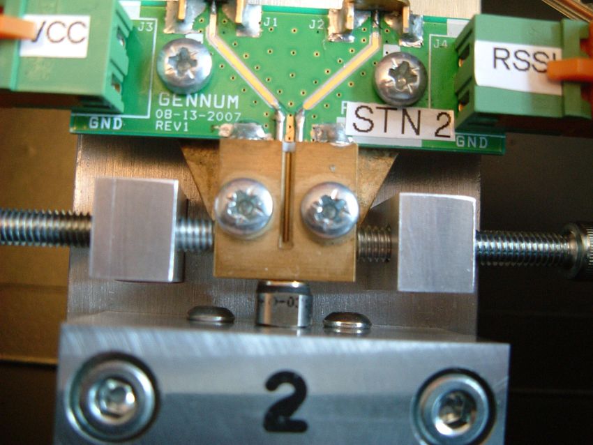
Connect the jumper cable supplied to the ROSA evaluation board. Insert the ROSA
leads into the evaluation board. Insert the ROSA into the appropriate optical
connector port and mount it into the holder as shown below taking care not to
damage the DUT leads. Jumper Cable
M4 Cap
Screws
Optical Connector
Port
- 17 -
Copyright 2009 Ktizo ConsultingOptical Wiggle Tester – instruction manual v1.1 June 09
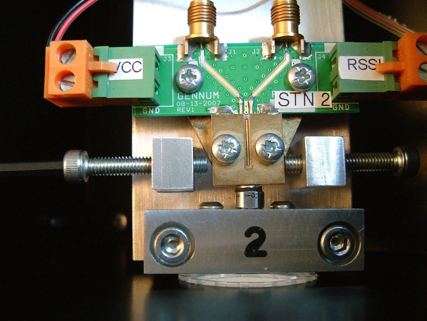
Open the OWT cover. Ensure the side mount screws are in the approximate positions
shown below. The end of the screws should be approximately 2mm away from their
respective mount block. Adjustment is made by rotating the base plate; this should
be done manually, and using the Allen key provided to adjust the screw positions.
Side Mount
Screws
Base Plate
Mount Assembly
Holes
Insert the two M4 cap screws into the holes of the mount assembly. Offer the
assembly up to the base plate and align it with the assembly mount holes. Using the
Allen key provided tighten the cap screws and fix the assembly into position.
Manually rotate the base plate to gain access to a side mount screw. Adjust the
screw position until the screw end face just touches the evaluation board mount
block.
Caution – damage to the DUT may occur if the screw is over tightened at this stage.
Rotate the base plate to gain access to the other side mount screw. Adjust the screw
position so that the screw end face touches the block.
- 18 -
Copyright 2009 Ktizo ConsultingOptical Wiggle Tester – instruction manual v1.1 June 09
Rotate the base plate and tighten the screw a small amount making sure there is
only minimal movement of the DUT. Rotate the base again and tighten the screw a
small amount making sure there is only minimal movement of the DUT. Repeat as
necessary until the evaluation board assembly is rigidly mounted.
Attach the jumper cable to jumper PCB.
Jumper
PCB
If the base plate position has moved and is no longer horizontal then manually adjust
it to be approximately horizontal. Close the OWT cover.
- 19 -
Copyright 2009 Ktizo ConsultingOptical Wiggle Tester – instruction manual v1.1 June 09
Testing
Preliminaries
Insert an appropriate patch cord into the optical connector port and connect the
other end to an optical source of known power.
Run the program and ensure ROSA calibration is complete.
Starting a test run
Press the start button
The software will perform the test on the first step of the program. A dialogue box
will appear, similar to the one below, instructing the user which weight (or none) to
attach.
The wiggle test results will then be plotted on the wiggle test results graph.
Adding weights to the patchcord
Some program steps may request weight to be added to the patchcord.
To add the 0.25lb (0.113Kg) weight…
Starting at a position approximately 200mm from the inserted end wind the patch
cord around the mandrel making sure all the mandrel channels are used. Using the
wire tie wrap supplied wrap the two ends of the patch cord as shown below
sufficiently tight to prevent any slippage of the patch cord. The combined weight
of the mandrel and metal insert is 0.25lbs (0.113Kg).
Wire tie
wrap
Mandrel
Weight
- 20 -
Copyright 2009 Ktizo ConsultingOptical Wiggle Tester – instruction manual v1.1 June 09
To add the 0.5lb (0.227Kg) weight...
Thread the Velcro holding strap through the lower mandrel hole as shown below.
Thread the strap through the hole of metal weight and attach the Velcro to itself.
Velcro holding
strap
Additional 0.25lb
weight
Finishing off
On completion of the test, mandrel assembly removal is the reverse of the process
detailed above.
Save the data if required before starting another test run.
- 21 -
Copyright 2009 Ktizo ConsultingOptical Wiggle Tester – instruction manual v1.1 June 09
Patchcord Calibration Methods
There are 3 methods of arranging the patchcord and calibrating the system. There
are advantages and disadvantages to each method.
1) Standard
After the calibration is complete, the optical path between the source and the DUT is
never disturbed.
Advantages: * Accurate power measurements
Disadvantages: * As the patchcord is wound around the mandrel, it tends to
twist
2) Ignore mandrel
The patchcord is wound around the mandrel, with the 0.25lb weight removed,
before the patchcord calibration is done.
Advantages: * Accurate power measurements
* The patchcord never becomes twisted
Disadvantages: * The weight of the mandrel 26g [0.05732lbs] is ignored in 0lb
test steps. i.e. A very small load is applied in 0lb steps.
3) Automatic compensation.
After the 0lb test step is complete, the patchcord is removed from the DUT** to allow
for easy winding around the mandrel. When the patchcord is re-connected to the
DUT, the software automatically compensates for any power variation caused by
breaking the optical connection.
To set this option, go to Settings and select the Recalibrate after first step option.
After the first step is complete, the software will request the user to disconnect the
patchcord from the DUT and attach the
mandrel. Then the patchcord should be re-
connected to the DUT. It is important that
there is no strain on the patchcord at this point
because the software then re-measures the
optical power and uses that to re-calibrate the optical path.
The software shows the change in optical power
due to breaking the optical path. Ideally this
should be 0μW. If the user is happy with the
change in power, click on the green tick. All
subsequent optical power measurements are
compensated by this amount. If the red cross is clicked on, the program will abort.
**
Alternatively, a back-to-back optical coupler can be used in the optical path to provide a way to uncouple the
light without disturbing the DUT.
- 22 -
Copyright 2009 Ktizo ConsultingOptical Wiggle Tester – instruction manual v1.1 June 09
The software will then ask the user to allow the
mandrel to hang freely. The remainder of the test
steps are now completed.
Advantages: *Optical path can be broken after the first program step.
*The patchcord never becomes twisted
*No extra weight applied in 0lb tests
Disadvantages: *Optical power measurements in program step 2 onwards are
compensated for any power change in the optical path.
Therefore the optical powers displayed on the results graph
are not actually offset values – but they are correctly
proportioned in relation to the 0lb test.
- 23 -
Copyright 2009 Ktizo ConsultingOptical Wiggle Tester – instruction manual v1.1 June 09
Saving Data
To save the current set of data, either press the Save Data Button
or go to:
File > Export Data
Data files are saved to the location specified in Settings > Paths > Saved data path.
The name of the data files is:
Serial Number_Batch Number_Comments[Date_Time]
The date and time are appended to the end of the file name if that option is selected
in Settings > Paths > Include date and time in filename.
Two files are saved:
1) A .csv file, which can be opened in any spreadsheet program.
It contains:
The version of the software
Date and time of the test
The test program name
The serial number, batch number and any comments relating to the DUT
All the test data from each program step
A summary of minimum, maximum and mean optical power fro each test step.
2) A .png file, which can be opened in any picture editing software, or imported into
Microsoft Word etc.
- 24 -
Copyright 2009 Ktizo ConsultingOptical Wiggle Tester – instruction manual v1.1 June 09
Advanced Software Operation
Loading and editing programs
To load a new program, go to
File > Load Program
This brings up a dialogue box as shown. Select which program you would like to use.
All OWT programs have the extension .wtp
To edit a program, go to
File > Edit Program
The Edit Program… dialogue box opens:
Controls Current
panel program
name
Program
panel
- 25 -
Copyright 2009 Ktizo ConsultingOptical Wiggle Tester – instruction manual v1.1 June 09
Load new program button – opens a dialogue box where a new program
can be selected.
Save program button – opens a dialogue box where the current program
can be saved.
Add/remove step buttons – adjusts the number of steps in the
current program.
Load default program – reloads the default program.
The program panel shows the steps included in the current program. Any of the
parameters in any step can be adjusted to the user’s requirements.
When finished, close the Edit Program… dialogue box by clicking the red cross in the
top right corner.
Adjusting Settings
Various settings can be adjusted. Go to:
Actions > Settings…
The various tabs shown group related settings together.
- 26 -
Copyright 2009 Ktizo ConsultingOptical Wiggle Tester – instruction manual v1.1 June 09
Calibration & reporting tab
Report in dB(m) [µW] – This selects whether data is displayed in the Results Graph in
dBm or µW. It also affects the units of the Y-axis on the results graph, the saved data
in the .csv file, and the units used in calibration.
Report absolute [relative] power – If absolute power is selected, the Results Graph
shows data in absolute units. i.e. in µW or dBm. If relative power is selected, a single
power measurement is taken at the start of the first program step, before motor
rotation starts. This is then used as a baseline for all subsequent measurements
during that program run. Values of power are then reported as Delta µW, or dB.
Include date and time in filename – If selected, the date and time of the start of the
program run are appended to the file name of any saved data.
Recalibrate after first step – the function of this option is described in detail in the
section ROSA Testing. It is only valid for systems that are capable of testing ROSAs.
Cursors tab
Include zero power marker? - If this setting is turned on, a thin line is displayed along
the y=0 axis.
Include test limits? - If this setting is turned on, two thicker lines are displayed,
equidistant to the y=0 axis. The limit can be adjusted if necessary to match the
application of the DUT.
Zero power
marker
Test limits
When the Report absolute [relative] power setting is set to absolute, none of the
cursors appear until the first optical power measurement is taken. The zero power
marker is then set to the initial power, and the test limits are set either side of it.
When the Report in dB(m) [uW] setting is changed, the test limits are set to a
default value, with the new units.
- 27 -
Copyright 2009 Ktizo ConsultingOptical Wiggle Tester – instruction manual v1.1 June 09
Paths tab
Default Program – This is the name of the program that will load each time the OWT
starts.
Programs Path – This is the location where custom programs are stored.
Saved Data Path – This is the location where saved data is stored.
Include date and time in filename - The date and time are appended to the end of
the file name if this option is selected.
Reports
The OWT can generate two types of report. The standard report consists of a .csv
data file that can be imported into a spreadsheet, and a .png image file. Additionally,
the OWT can produce an HTML report that can be viewed in a standard web
browser. The HTML report contains all the same data as the standard report but has
customisable header, footer and company logo graphic.
Generate raw data files? - If this is selected, the .csv data file and the .png image files
are generated.
Generate HTML report? - If this is selected, a customised HTML report file is
generated.
Logo path – This is the name of the image file that is used to customise the HTML
report.
The HTML report generation function is an optional feature.
Other settings
Language – This adjusts the language that the Optical Wiggle Tester works in.
Various language packs are available.
Port Name – The Optical Wiggle Tester automatically detects all valid COM ports and
list them here. If the USB port is used, it will appear to Microsoft Windows as a COM
port.
If for some reason the selected COM port is invalid, at start-up, the software will give
an error message as shown:
In this situation, change the COM port and
save the settings. The software will re-start.
On Microsoft Windows systems, a list of valid COM ports can be found using the
Device Manager. Go to: Start > Run > devmgmt.msc
- 28 -
Copyright 2009 Ktizo ConsultingOptical Wiggle Tester – instruction manual v1.1 June 09
Technical Specifications
Power Supply
External supply option:
10V-14V DC (12V nominal). Approximately 1.3A
2A 20mm Anti-surge fuse.
Internal supply option:
120V – 250V AC.
1A 20mm Anti-surge fuse.
System Requirements
PC (2.0GHz processor, 2GB RAM)
Windows XP, service pack 2 or higher
1 x USB port or RS232 (serial) port
System Communications
1 x USB 2.0 port
1 x RS232 port
Both feature galvanic isolation. i.e. the PC and the port are electrically isolated from
the OWT’s power supplies and internal systems.
If the USB port is connected, it will take priority over the RS232 port. Ktizo
recommend using the USB port.
Physical Dimensions
Size: 153mm high x 236mm wide x 327mm deep
Weight: Approximately 8.5 Kg
Environmental Specifications
Operating temperature range: +5°C to +45°C
The OWT is designed to be used in a normal lab environment.
- 29 -
Copyright 2009 Ktizo ConsultingOptical Wiggle Tester – instruction manual v1.1 June 09 Optical Wiggle Testing Speed of rotation: 1,2,3,4,5 rpm Speed of rotation accuracy: ±5% (1,2,3,4 rpm); ±15% (5 rpm) Samples can be taken every 4,5,6,12,30,45° - software selectable Sample accuracy:
Optical Wiggle Tester – instruction manual v1.1 June 09
Auxiliary power supplies (optional)
3.3V and/or 5.0 V supplies are standard options. Custom voltages are possible -
please enquire.
Voltage tolerance: ±2%
2.1mm power socket
Current is internally limited to 0.5A per supply
Auxiliary SFP slot (optional)
3.3V supply using the INF-8074i MSA-approved supply filter
Molex 74737-0004 SFP cage
Tyco 1367073-1 SFP 20-pin connector
Voltage tolerance: ±2%
Current is internally limited to 0.5A (total for Tx and Rx supplies)
Software monitoring of TxFault, LOS, MOD_DEF 0
Software control of Tx-Disable
The OWT is highly configurable and customisable. Please ask for
further information about any of the specifications.
- 31 -
Copyright 2009 Ktizo ConsultingOptical Wiggle Tester – instruction manual v1.1 June 09
Ordering Information
The Optical Wiggle Tester is available with a variety of options.
OWT01 / xx / xx / xx / xx
Optical measurement capability
RO - ROSA
TO - TOSA
RX – Module Rx
TX – Module Tx
Optical Interfaces Supplied
SF – SFP, SFP+
XF - XFP
X2 - X2
GB - GBIC
C1, C2 etc - custom
Power supply
IN - Internal mains multi-voltage
EX - External supply (customer supplied)
E2 - External low voltage (Ktizo supplied)
Other options
RO - Reference SFP slot
OP - Internal optical power meter
33 – Auxiliary 3.3V output
50 – Auxiliary 5.0V output
HT – HTML report generator
Custom-designed ROSA and TOSA and module mounts are available on request.
Various spares and accessories are also available.
- 32 -
Copyright 2009 Ktizo ConsultingOptical Wiggle Tester – instruction manual v1.1 June 09
Ktizo Consulting
518 Norwich Road, Ipswich, IP1 6JR. UK
Phone: +44 750 200 4611
email: sales@ktizo.co.uk
web: www.ktizo.co.uk
- 33 -
Copyright 2009 Ktizo ConsultingOptical Wiggle Tester – instruction manual v1.1 June 09
- 34 -
Copyright 2009 Ktizo ConsultingYou can also read