Flare Fireplaces Power Vent Installation Guide - Flare Fireplaces PV system v 3.0
←
→
Page content transcription
If your browser does not render page correctly, please read the page content below
Flare Fireplaces Power Vent Installation Guide
[Flare Fireplaces PV system] v 3.0
CONTENTS

FLARE FIREPLACES – FRAMELSS IN EVERY WAY ...........................................................................................................3

 SAFTEY INFO AND WARNINGS ...................................................................................................................................4

   SAFETY ............................................................................................................................................................................ 6

MANUAL MODEL LIST & INFORMATION ......................................................................................................................6

POWER VENTING OVER VIEW......................................................................................................................................7

POWER VENT DRAWINGS ............................................................................................................................................7

   HORIZONTAL END OF LI NE POWER VENT DRAWING ..................................................................................................... 7
   HORIZONTAL FRAMING DIMENSIONS ............................................................................................................................ 8
   HORIZONTAL POWER VENT PART LIST ..................................................................................................................................... 9
   VERTICAL END OF LINE POWER VENT DRAWING .......................................................................................................... 10
   VERTICAL POWER VENT PART LIST........................................................................................................................................ 12
   IN-LINE POWER VENT DRAWING .................................................................................................................................. 13
   IN-LINE POWER VENT PART LIST ................................................................................................................................... 14

CLEARANCES ............................................................................................................................................................. 15

   MINIMUM COMBUSTIBLE CLEARANC ES FROM VENT .................................................................................................. 15
     VERTICAL TERMINATION .......................................................................................................................................... 15
     Vertical Multiple Terminations ................................................................................................................................. 16
     HORIZONTAL TERMINATION .................................................................................................................................... 16
   VENT TERMINATION CLEARANCES ......................................................................................................................................... 18

VENT R ESTRICTOR SETUP ......................................................................................................................................... 20

POWER VENT ELECTRICAL CONNECTION ................................................................................................................... 21

   FIREPLACE ELECTRICAL DRAWING WITH POWER VENT OPTION .................................................................................. 22
   POWER VENT BOARD ELECTRICAL DRAWING ............................................................................................................... 23

VENTING ................................................................................................................................................................... 24

   3X5 VENT CONNECTION AND DIRECTION ..................................................................................................................... 26

REPLACEMENT PARTS................................................................................................................................................ 27

APPENDIX .................................................................................................................................................................. 28

   YEARLY SERVICE ............................................................................................................................................................ 28
   PILOT MAINTENANCE ................................................................................................................................................... 29
   BURNER MAINTENANCE ............................................................................................................................................... 29
   VENT MAINTENANCE .................................................................................................................................................... 29
   DOUBLE GLASS FANS .................................................................................................................................................... 29
   MAINTENANCE LOG ..................................................................................................................................................... 30
   WARRANTY POLICY ....................................................................................................................................................... 31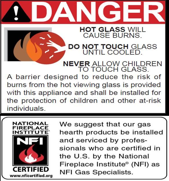
FLARE FIREPLACES – FRAMELSS IN EVERY WAY

Flare Fireplaces is where innovation, quality and luxury come together to form new ideas.

By combining superior raw materials, contemporary design, creative technology and a frameless way of thinking, we
have created a full line of direct-vent fireplaces that are luxurious, simple to operate and efficient.

Our Fireplaces are distinguished by their clean design, superior build quality and unique features.
SAFTEY INFO AND WARNINGS

                              WARNING!

                                                   Series, in Canada.

      This appliance is only for use with the type(s) of gas indicated on the rating

                 plate. A conversion kit is supplied with the appliance.

                                                        At High Altitudes.

                              WARNING!
                                                                             result causing
                             WARNING!
                   property damage, personal injury or loss of life.

                                                                               supplier.

                             WARNING!

                                     APPLIANCE

                             WARNING!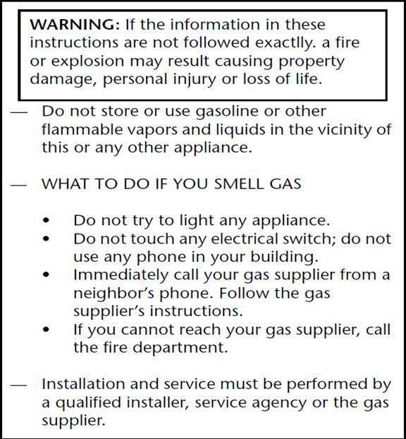
WARNING!

    from hot surfaces

 WARNING!

 WARNING!

 WARNING!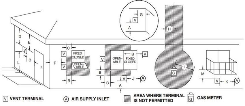
SAFETY

  CSA CERTIFICATION

  All our fireplaces are tested and have been certified to meet stringent CSA guidelines, ensuring optimum quality,
  safety and efficiency.

  All our fireplaces have been certified and tested to work with Natural Gas or Propane. Certification Information:

  ANSI Z21.88/CSA 2.33-2014- Vented Gas Fireplace Heaters

  CSA CLASSES:

  CLASS 2901 84 / CLASS 2901 04

  MANUAL MODEL LIST & INFORMATION

  The Following manual should be used for Flare Fireplaces Models:

                           •    Flare Front 30-100 “

                           •    Flare See-Through 30-100”

                           •    Flare Corner Right and Left 30-100”

                           •    Flare Double Corner 30-100”

                           •    Flare Room Definer 45-100”

  To simplify the installation and operation, all models above share the same gas valve system, remote, gas connection,
  glass type. All warnings and instructions apply to all models.

  Flare Fireplaces Power Vent system must only be connected to M&G 3x5 venting system.

  For detailed chimney installation information please use the M&G DuraVent direct vent installation manual:
  http://www.DuraVent.com

Installation MUST comply withlocal,regional, state and national codes andregulations. Consult insurance carrier, local building
          inspector, fire officials or authorities having jurisdiction over restrictions, installation inspection and permits.

              This installation must conform to local codes. In the absence of local codes, you must comply with the

        National Fuel Gas Code, ANSI Z223.1-latest edition in the U.S.A. and the CAN/CGA B149 Installation Codes in Canada.

     Improper installation, adjustment, alteration, service or maintenance can cause injury or property damage. For
     assistance or additional information, consult a qualified service technician, service agency or your dealer.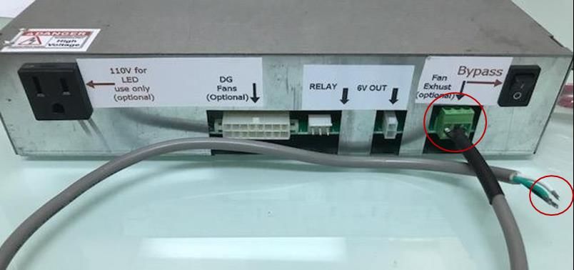
POWER VENTING OVER VIEW
In the event of a vent route that is unsupported based on the Gravity Vent Tables shown in the Flare Install Manual,
Flare Fireplaces may use a power vent to accommodate any extremely long, or negative degree venting routes. The 3
power vent options allow the fireplace to operate in vent conditions that would not be possible without the powered
fan. With a power-vent you can install a 90-elbows right off the top of the fireplace. When using the power vent
system, it is critical that the vent path remain completely sealed for the power vent system to operate. The vent
length and restrictor level should be set based on number of feet, number of elbows, and the vent termination.
The Flare power vent system is an optional feature and can be used on a Flare Fireplace using Double Glass or our
Invisible Mesh safety screen. It comes in 3 different models:
• End of Line Power Vent Vertical
• End of Line Power Vent Horizontal
• In-Line Power Vent
The system is designed and tested with DuraVent 3x5 gasket direct vent pipes. It is critical for the safety and operation
of the system to use the DuraVent 3x5 gasket system.
See the link below for a DuraVent catalog & vent parts with part numbers:
https://www.DuraVent.com/docs/product/CVS_Catalog.pdf
All three Flare Power Vent systems can be installed with up to 8 elbows with up to 100ft vent run.
A minimum length of 20ft venting is required between the appliances. Do not install any Power Vent system if the
minimum length is below 20 ft. The three Power Vent systems can be installed with a maximum of 6ft vent run below
the fireplace.
POWER VENT DRAWINGS
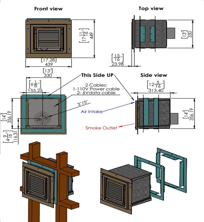
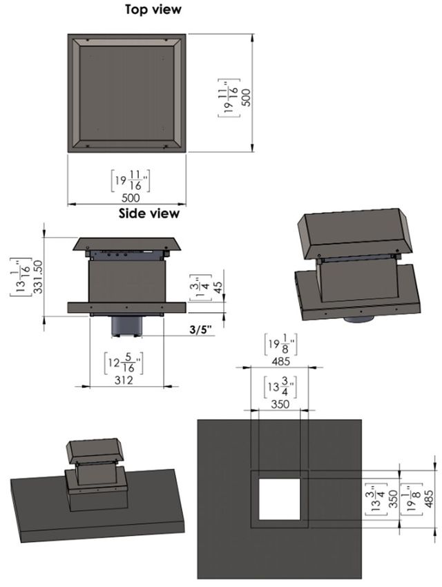
HORIZONTAL END OF LI NE POWER VENT DRAWING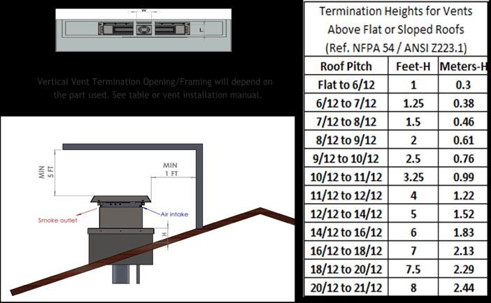
HORIZONTAL FRAMING DIMENSIONS
ROUGH OPENING FOR CUT-OUT: 13 ½ W x 14 ½ H
HORIZONTAL POWER VEN T PART LIST

  PV Horizontal Part List:

              ITEM
                             PART NUMBER                      DESCRIPTION
               NO.
                1             W-F-08                     PV External Cover
                2             W-F-14                      PV Board Cover
                3             W-F-19                      PV Board Holder
                4             W-F-17                   M4 stain steel screws
                5           Draft switch       HUBA Control to measure the fan pressure
                6          Electric Board                 Electronic Board
                7               Fan                          Cooling Fan
                8         Smoke blower                Main Fan For Exhausting
                9       Smoke blower carrier            Smoke outlet holder
                         Housing of smoke
                10                                          PV Whole block
                              blower
                11            W-F-10              Bracket For fixing the PV to the hole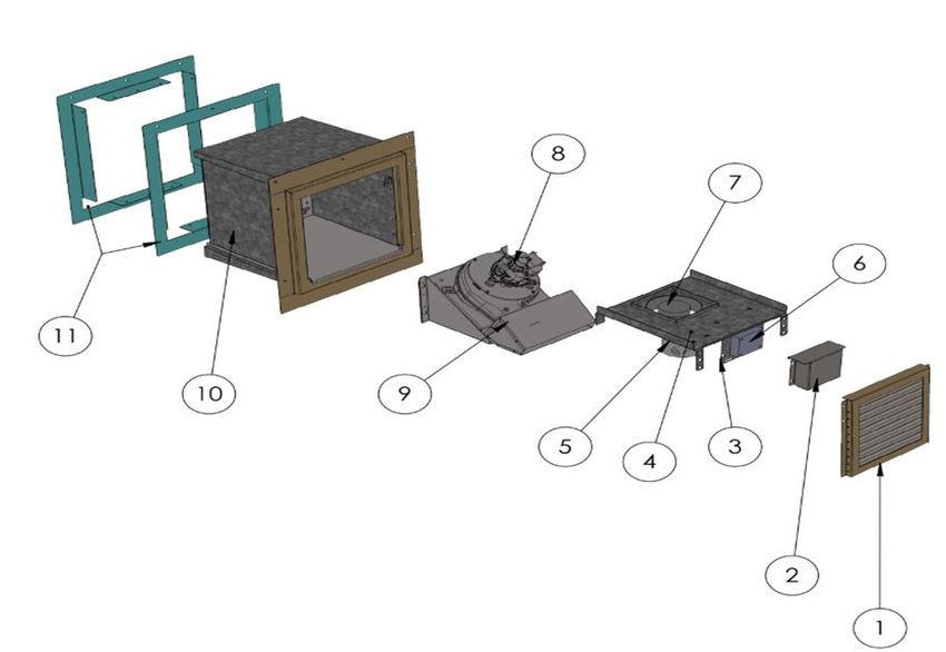
VERTICAL END OF LINE POWER VENT DRAWING

                                          ROOF
VERTICAL POWER VENT PART LIST
ITEM
PART NUMBER DESCRIPTION
NO.
1 Housing of smoke blower- Vertical The Whole Block For PV Vertical
2 Fan-03+04 Main Fan Holder
3 Smoke Blower Main Fan for Exhausting
4 Fan-08 Inner upper cover for smoke outlet
5 Draft switch HUBA Control for pressure measuring
6 Electric Board Electronic board cover
7 Fan Cooling fan
8 Fan-12 Cooling fan holder
9 Fan-06 External Upper CoverIN-LINE POWER VENT D RAWING
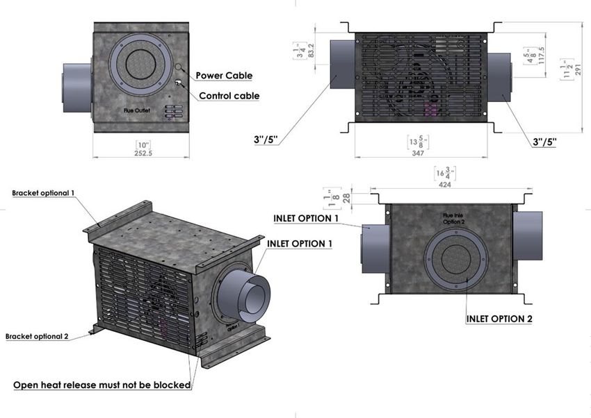
IN-LINE POWER VENT P ART LIST

    ITEM NO.              PART NUMBER                   DESCRIPTION
       1                    FanExNet                    External Cover
       2                        Fan                       Cooling fan
       3                  Smoke blower                     Main Fan
       4                   Draft switch                 HUBA Control
       5                    FanExDish               Electronic Board Holder
       6          Housing of smoke blower-In Line    IN-LINE Whole Block
CLEARANCES
Clearance between the vent pipe and combustible materials must be maintained at 3” inches top and 1” for side and
below. Maintain the same clearance from the power vent box to any combustible materials.
• HORIZONTAL VENT CLEARANCES: A minimum clearance of 3” (76mm) to the top
and 1” (51mm) to the sides and bottom of the vent pipe on all horizontal runs to
combustibles is required.
• VERTICAL VENT CLEARANCES: A minimum of 1” (25mm) all around the vent pipe
on all vertical runs to combustibles is required except for clearances in appliance
enclosures.
MINIMUM COMBUSTIBLE CLEARANC ES FROM VEN T
VERTICAL TERMINATION
Please make sure clearances to combustible is maintained based on vent part used. Opening size will depend on the
vent size/fireplace size and DuraVent part # to be used.
Please make sure to follow DuraVent installation instruction: http://DuraVent.com/docs/product/L916.pdf
Minimum height from roof lowest discharge openingVERTICAL MULTIPLE TERMINATIONS
• If using decorative cap cover/s, this distance may need to be increased. Refer to the
installation instruction supplied the decorative cap cover
• In a staggered installation with both gas and wood or fuel oil termination, the
wood or fuel oil termination cap must be higher than
HORIZONTAL TERMINATI ON
A minimum distance of 18 inches should be kept between multiple horizontal terminations.VENT TERMINATION CLE ARANCES
A *12 inches (30 cm) min. Clearances above grade, veranda, porch, deck, or balcony
B *12 inches (30 cm) min. Clearance to window or door that may be opened
C 12 inches (30 cm) min. Clearance to permanently closed window recommended to prevent
condensation on window
D 30 inches (76 cm) min. for Flare units 80” Vertical clearance to ventilated soffit located above the terminal
and 100” within a horizontal distance of 2 feet (60 cm) from the edge of the
terminal
12 inches (46 cm) min. for Flare units 70”
and below (vinyl surfaces require 24 inches
(61 cm) min.)
E 30 inches (76 cm) min. for Flare units 80” Clearance to unventilated soffit.
and 100”
18 inches (46 cm) min. for Flare units 70”
and below (vinyl surfaces require 24 inches
(61 cm) min.)
F 6 inches (15 cm) min. Clearance to outside corner
G 6 inches (15 cm) min. Clearance to inside corner
H 3 feet (90 cm) min. *Not to be installed above a meter/regulator assembly within 3 feet
(90 cm) horizontally from the center-line of the regulator
I 3 feet (90 cm) min. Clearance to service regulator vent outlet
J *12 inches (30 cm) min. Clearance to non-mechanical air supply inlet to building or the
combustion air inlet to any other appliance
K *6 feet (1.8 m) min. Clearance to a mechanical air supply inlet
L *7 feet (2.1 m) min. +Clearance above paved side-walk or a paved driveway located on
public property
M **20 inches (51 cm) min. Clearance under veranda, porch, deck, or balcony+A vent shall not terminate directly above a side-walk or paved driveway which is located between two single family dwellings and serves both dwellings* ** only permitted if veranda, porch, deck, or balcony is fully open on a minimum of 2 sides beneath the door* *as specified in CGA B149 Installation Codes, note: local Codes or Regulation may require different clearances *for U.S.A. Installations follow the current National Fuel Gas Code, ANSI Z223.1 ***Horizontal vent termination minimum clearance to adjacent structure or fence is 48”. **** Minimum 24” horizontal clearance to any surface (such as an exterior wall) for vertical terminations
VENT R ESTRICTOR SET UP
Flare Fireplace direct vent system is equipped with a vent restrictor. Use the chimney path installation planning
chapter to determine what the vent restrictor setup should be for your installation.
• The unit leaves the factory with the vent restrictor open.
• The vent restrictor is adjusted using a 10mm wrench below the front upper frame.
• The vent restrictor setting is from 1 (minimum restriction) to 6 (max restriction).
• The installer will document the restrictor setting in the end of the installation.
Restrictor not set right:
Restrictor position must be opened if the flame has the following characteristics:
• Flame is excessively tall and lifting.
• Flame lacks movement.
Restrictor position needs to be closed more if the flame has the following characteristics:
• Flame height is low.
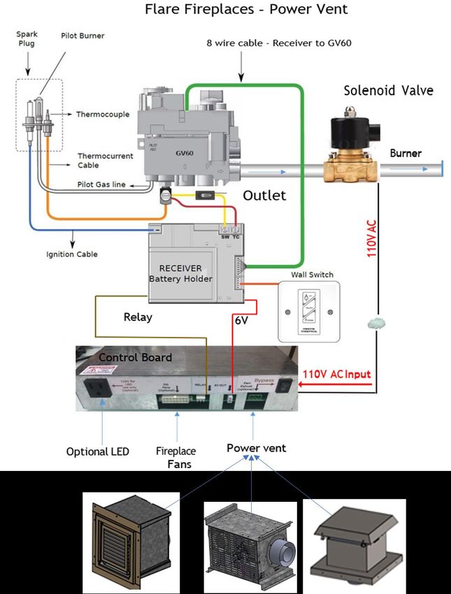
• Flame has excessive movementPOWER VENT ELECTRICAL CONNECTION
• All Flare Fireplaces PV system are connected to the Fireplace with a low voltage 6V cable.
• In addition, the Power Vent system will require a separate 15A power source connected to
it. The electrical line to the Power Vent must supply 120 Volts, 60 Hz, and 15 Amps
(maximum draw). Dedicated circuit for the Power Vent is recommended.
• The appliance, when installed, must be electrically grounded in accordance with local codes
or, in the absence of local codes, with the National Electrical Code, ANSI/NFPA 70, or the
Canadian Electrical Code, CSA C22.1.
Electrical control connection to the PV system
• The PV system is connected to the Fireplace control system with a low voltage (6V) 3 wire
cable.
• Cable to be used is 18 AWG-3 copper wires. Cable can be ordered from Flare or
sourced from any hardware store (18 AWG 4 wire can also be installed, use only 3
wires).
• Connect low voltage cable and match to colors on the terminal between the PV
harness. (White to White, Black to Black & Green to Green)
• Fans and sensors on the main board are optional and will be included on double
glass systems.
Fireplace board example above
PV electrical connection and 3 wire cableFIREPLACE ELECTRICAL DRAWING WITH POWER VENT OPTION
POWER VENT BOARD ELE CTRICAL DRAWING
VENTING

To calculate the vent runs use the following tables and instructions. Please note that power vent runs are model
(burner) specific. Use the tables below to calculate the restrictor setting.

         •   A minimum length of venting is required between the appliance. Do not install power vent system if the
             minimum length is below 20ft.

Minimum Run when using power vent - 20 ft (physical length not calculated)

90 Degree elbow = 6 Ft

45 Degree elbow = 3 Ft Vent termination = 3 Ft

Flare-30 (Flare-FF, Flare-ST, Flare-RC, Flare-LC, Flare-DC)

             Run Length            Restrictor Setting          Burner Type            Unit Type
               20--28                      5                       B                   Flare 30
               28--40                      4                       B                   Flare 30
               40--52                      3                       B                   Flare 30
               52--64                      3                       B                   Flare 30
               64--76                      3                       B                   Flare 30
               76--88                      2                       B                   Flare 30
              88--100                      2                       B                   Flare 30

Flare-45 (Flare-FF, Flare-ST, Flare-RC, Flare-LC, Flare-DC, Flare-RD)

             Run Length            Restrictor Setting          Burner Type            Unit Type
               20--28                      5                        C                  Flare 45
               28--40                      4                        C                  Flare 45
               40--52                      3                        C                  Flare 45
               52--64                      3                        C                  Flare 45
               64--76                      3                        C                  Flare 45
               76--88                      2                        C                  Flare 45
              88--100                      2                        C                  Flare 45

Flare-50 (Flare-FF, Flare-ST, Flare-RC, Flare-LC, Flare-DC, Flare-RD)

             Run Length            Restrictor Setting          Burner Type            Unit Type
               20--28                      4                       D                   Flare 50
               28--40                      4                       D                   Flare 50
               40--52                      3                       D                   Flare 50
               52--64                      3                       D                   Flare 50
               64--76                      3                       D                   Flare 50
               76--88                      2                       D                   Flare 50
              88--100                      2                       D                   Flare 50
Flare-60 (Flare-FF, Flare-ST, Flare-RC, Flare-LC, Flare-DC, Flare-RD)
Run Length Restrictor Setting Burner Type Unit Type
20--28 4 E Flare 60
28--40 4 E Flare 60
40--52 4 E Flare 60
52--64 3 E Flare 60
64--76 3 E Flare 60
76--88 2 E Flare 60
88--100 1 E Flare 60
Flare-70 (Flare-FF, Flare-ST, Flare-RC, Flare-LC, Flare-DC, Flare-RD)
Run Length Restrictor Setting Burner Type Unit Type
20--28 4 F Flare 70
28--40 4 F Flare 70
40--52 3 F Flare 70
52--64 3 F Flare 70
64--76 2 F Flare 70
76--88 1 F Flare 70
88--100 1 F Flare 70
Flare-80 (Flare-FF, Flare-ST, Flare-RC, Flare-LC, Flare-DC, Flare-RD)
Run Length Restrictor Setting Burner Type Unit Type
20--28 4 G Flare 80
28--40 4 G Flare 80
40--52 3 G Flare 80
52--64 3 G Flare 80
64--76 2 G Flare 80
76--88 1 G Flare 80
88--100 1 G Flare 80
Flare-100 (Flare-FF, Flare-ST, Flare-RC, Flare-LC, Flare-DC, Flare-RD)
Run Length Restrictor Setting Burner Type Unit Type
20--28 3 H Flare 100
28--40 3 H Flare 100
40--52 2 H Flare 100
52--64 1 H Flare 100
64--76 1 H Flare 100
76--88 1 H Flare 100
88--100 1 H Flare 1003X5 VENT CONNECTION AND DIRECTION
The Flare Power Vent system uses DuraVent 3x5 CVS vent system. The DuraVent CVS vents includes a lock system and
a silicone gasket on every side of the vent. Make sure you follow the DuraVent CVS installation manual:
http://DuraVent.com/docs/product/L916.pdf
Please follow the vent marking for directing of vent flow. The direction is clearly marked on the 3x5 vents, the
Fireplace vent adapter and the Power Vent adapters. See the pictures below for clarification on the Power Vent
system vent connection:
Power Vent INLET Power Vent OUTLETREPLACEMENT PARTS
See below for flare replacement part list.
• Please contact your fireplace dealer to purchase any replacement part.
• Please make sure to provide the description and part number.
• Please make sure to use a certified installer for any service related to your fireplace.APPENDIX
WARNING!
It is recommended that a qualified service technician perform a routine inspection
at the beginning of each heating season.
Disconnect power before attempting maintenance or repair of the fireplace.
Installation and maintenance must be performed by an authorized qualified installer,
service agency or gas supplier.
Any safety screen or guard removed for servicing placed back before operating this appliance.
DO NOT USE this appliance if any part has been under water. Immediately call a
qualified service technician to inspect the unit and to replace any part of the
control system and any gas valve that has been under water or impacted.
Any alteration to the product that causes soot or carbon to form and results
in damage is not the responsibility of the manufacturer.
Do not modify or substitute any part of this appliance.
Inspect the external vent cap on a regular basis to make sure that no debris, plants,
trees, or shrubs are interfering with the air flow.
Do not operate the fireplace without the fireplace glass.
It is imperative that control compartments, screens, or fans system for double
glass be kept clean and free of obstructions. These areas provide the air necessary
for safe operation.
Light the heater using the built-in igniter. Do not use matches or any other external
device to light your heater.
Never remove, replace, modify or substitute any part of the heater unless
instructions are given in this manual. All other work must be done by a trained
technician. Don't modify or replace orifices.
YEARLY SERVICE
Failure to inspect and maintain the fireplace may lead to improper combustion and a potentially dangerous situation.
We recommend the following procedures be done by a qualified technician.
Glass Maintenance
• Always use suction cups to remove the fireplace glass. Use the manual procedure for instruction on how
to remove the fireplace glass. Always use gloves when removing the glass to protect your hand and
prevent finger prints on the glass.
• DO NOT USE abrasive cleaners on the glass panels. DO NOT ATTEMPT to clean the glass panels when
they are hot.
• Do not use normal household (usually ammonia-based) glass cleaners to clean the glass as these cleaners
can leave a permanent stain. Only a gas fireplace glass cleaner should be used.
• Verify no cracks or breakage in the glass.
• Place glass in a safe location to prevent breakage.
• Never attempt to operate the fireplace without the fireplace glass.PILOT MAINTENANCE
• Visually inspect the pilot flame. The pilot flame should be always present when the fireplace is in
operation.
• Make sure the pilot flame has two flame tips pointing to the flame sensor (thermocouple) and to the
center of the burner.
• Make sure the pilot area is clean from any dust, media or any other debris that may disrupt the
operation of the ignition system. Lint or foreign material must be removed with a brush or vacuum.
• Verify fireplace ignition using the remote or wall switch. Verify electronic ignition, sparking sequence,
pilot operation and burner ignition.
BURNER MAINTENANCE
• The flames from the burner should be visually checked. The flame should have a blue base and yellow
tops and be candle-like in appearance.
• If excessive soot is found inside the firebox area, the fireplace will require adjustment. Verify the air
shutter and vent restrictor setting and document any changes.
• If the flame becomes sooty, dark orange in color, or extremely tall, do not operate the heater.
• Measure gas pressure. Inlet W.C., Outlet W.C.
VENT MAINTENANCE
The following venting system inspection by a qualified service technician is recommended every six months:
• Inspect for excessive condensation, e.g. water droplets forming in the inner lining and subsequently
dripping out of the joints. This can cause corrosion in the system.
• Check for corrosion in areas exposed to the elements. Where rust spots or holes have appeared, these
must be immediately replaced.
• Ensure that there is no foreign material in the vents. Survey by removing the cap and shining a light
down the vent.
• Check all joints and pipes to make sure that nothing has been disturbed or loosened.
DOUBLE GLASS FANS
• Disconnect power to the Flare control system.
• Remove the external glass and the covering trim.
• Inspect the fans around the Flare firebox and make sure they are all turning.
• Clean all fans with a brush and vacuum to remove any dust or debris.
• Inspect the lower fireplace intake. Clean the lower vent intake with a brush and vacuum any dust or
debris.
• Connect back the Flare control power and press the Flare remote arrow down. Make sure all fans are
working properly.
• Turn off the fans and install back the trim and glass.MAINTENANCE LOG
Flare Fireplaces – Maintenance log
Following document should be used by the service technician. A copy should be kept with the technician and owner for future
reference
Service Date: Unit Information
Model Type and Size: Serial #: Owner Information
Name: Address Technician Information
Name: Company Name Technician
NPI # Service Information
Yearly Maintenance: Other:
Details:WARRANTY POLICY
Flare Fireplaces takes extreme measures to assure all products are tested, verified, and are free from defects prior to
leaving our warehouse.
Our Factory is subject to high quality standard and is under the supervision of the CSA organization.
Flare Fireplaces Warranty information:
• 1-year Limited Warranty on the gas valve, remote, pilot burner assembly, electric components and fan
motors, interior decorative media.
• 5 Year Limited Warranty for Ceramic glass (thermal breakage only)
• 10-year Limited warranty on the firebox and burners
Flare warranty shall be effective only if the original purchaser of the fireplace appliance is registered with Flare
Fireplaces within thirty days of the date of purchase.
Minor warping of certain parts or discoloration is normal and is not considered a defect that is covered by this
warranty. Major disruption and buckling of parts can be caused by over-firing of your Fireplace. Over-firing above
rated value specified in the manual is contrary to the manufacturer’s instructions and may void this warranty.
All installations must be performed by a qualified technician in accordance with applicable local and national
requirements.
Installations must be done in accordance with the appliance manual. The Limited Warranty applies only if the product
is installed in the United States or Canada and only if installed, operated and maintained in accordance the attached
product manual.
Warranty coverage begins on the date of original purchase.
It is the responsibility of the installer to ensure the appliance is firing as per the rating plate.
Any part that is found in our judgment to be defective shall be repaired, replaced or refunded at Flare Fireplaces
option.
This warranty only covers Flare Fireplaces appliances that are purchased through a Flare Fireplace authorized dealer
or distributor.
The warranty is only valid while the Flare Fireplace appliance remains at the site of original installation.
Contact your installing dealer for warranty service. If the installing dealer is unable to provide necessary parts, contact
the nearest Flare Fireplaces authorized dealer or supplier
All installations must be performed by a qualified technician in accordance with applicable local and national
requirements.
Warranty coverage begins on the date of original purchase.
It is the responsibility of the installer to ensure the appliance is firing as per the rating plate.
Any part that is found in our judgment to be defective shall be repaired, replaced or refunded at Flare Fireplaces
option.
This warranty only covers Flare Fireplaces appliances that are purchased through a Flare Fireplace authorized dealer
or distributor.The warranty is only valid while the Flare Fireplace appliance remains at the site of original installation. Contact your installing dealer for warranty service. If the installing dealer is unable to provide necessary parts, contact the nearest Flare authorized dealer or supplier. This warranty is void if: Use of an unauthorized type of media in the firebox. The appliance has been over-fired or operated in atmospheres contaminated by chlorine, fluorine, or other damaging chemicals. Over-firing can be identified by, but not limited to, warped plates or tubes, rust colored cast iron, bubbling, cracking and discoloration of steel or enamel finishes. The appliance is subjected to prolonged periods of dampness or condensation. There is any damage to the appliance or other components due to water or weather damage which is the result of, but not limited to, improper chimney or venting installation. Holes have been drilled in to the fireplace for any reason. Exclusions: This warranty does not apply to any component that shows evidence of misuse, abuse, improper installation, accident or lack of maintenance. Flare Fireplaces is not responsible for televisions, mantles, surrounds or finishing material around the fireplace. Flare Fireplaces may at its discretion discharge all obligations by refunding the wholesale price of the defective part. The Limited Warranty covers only parts and labor as provided above. Flare Fireplaces will not be responsible for materials, components or construction, which are not manufactured or supplied by Flare Fireplaces or for the labor necessary to install, repair or remove such materials, components or construction.
You can also read