TRU Train Recording Unit (MPRR) - Quick Reference Guide - This Quick Reference covers the installation of a Multi Protocol Rail Reader (MPRR) ...
←
→
Page content transcription
If your browser does not render page correctly, please read the page content below
TRU® Train Recording Unit (MPRR)
                                                                      Quick Reference Guide
                                                                                  16-0013-001 Rev A 05/2014

This Quick Reference covers the installation of a Multi Protocol Rail Reader (MPRR) based TRU.
FCC Site Licensing Because TransCore Readers used with the TRU System may radiate more than 3 milliwatts of RF power, their use requires licensing under Federal Communications Commission (FCC) Section 90.239. An FCC license provides the user with the legal authorization to operate the AI1200 Reader system on the licensed frequencies at the site specified in the license. The FCC license also provides the user with protection and authorization to maintain the system should any other RFID product be used in the licensed area after the TransCore Reader equipment is installed. The site owner must complete and file form 601, FCC Application for Wireless Telecommunications Bureau Radio Service Authorization. Forms are available online at the FCC internet site http://www.fcc.gov/forms. The authorized frequency band for this product in the United States is 902 to 904 MHz and 910 – 921.5 MHz.
Table of Contents
Getting Started . . . . . . . . . . . . . . . . . . . . . . . . . . . . . . . . . . . . . . . . . . . . . . . . . . . . . . . . . . . . . . . 5
      TRU Lights and What They Mean . . . . . . . . . . . . . . . . . . . . . . . . . . . . . . . . . . . . . . . . . 5
      External Interfaces. . . . . . . . . . . . . . . . . . . . . . . . . . . . . . . . . . . . . . . . . . . . . . . . . . . . . . 8
      Electrical and Communications Requirements . . . . . . . . . . . . . . . . . . . . . . . . . . . . . . . .9
Installing the TRU . . . . . . . . . . . . . . . . . . . . . . . . . . . . . . . . . . . . . . . . . . . . . . . . . . . . . . . . . . . . 9
      Tools You Will Need . . . . . . . . . . . . . . . . . . . . . . . . . . . . . . . . . . . . . . . . . . . . . . . . . . . .9
      Mounting the TRU . . . . . . . . . . . . . . . . . . . . . . . . . . . . . . . . . . . . . . . . . . . . . . . . . . . . . .9
      Connecting the Multiprotocol Rail Reader(s) . . . . . . . . . . . . . . . . . . . . . . . . . . . . . . . .10
      Connecting Power . . . . . . . . . . . . . . . . . . . . . . . . . . . . . . . . . . . . . . . . . . . . . . . . . . . . .10
      Connecting the Wheel Detector Segments . . . . . . . . . . . . . . . . . . . . . . . . . . . . . . . . . . .10
      Connecting and Testing the Presence Loop . . . . . . . . . . . . . . . . . . . . . . . . . . . . . . . . . .11
      Connecting Communications . . . . . . . . . . . . . . . . . . . . . . . . . . . . . . . . . . . . . . . . . . . . .11
      Correct Grounding . . . . . . . . . . . . . . . . . . . . . . . . . . . . . . . . . . . . . . . . . . . . . . . . . . . . .11
Accessing the TRU User Interface Main Menu . . . . . . . . . . . . . . . . . . . . . . . . . . . . . . . . . . . 14
Entering the Site Maintenance Menu (SITEMNT) . . . . . . . . . . . . . . . . . . . . . . . . . . . . . . . . 15
Configuration Menu (CONFIG) . . . . . . . . . . . . . . . . . . . . . . . . . . . . . . . . . . . . . . . . . . . . . . . . 15
Reports Menu (RPTS) . . . . . . . . . . . . . . . . . . . . . . . . . . . . . . . . . . . . . . . . . . . . . . . . . . . . . . . . 17

List of Figures
Single Track - Track 1 . . . . . . . . . . . . . . . . . . . . . . . . . . . . . . . . . . . . . . . . . . . . . . . . . . . . 6
Active LEDs - Dual Track - Track 1 and 2 . . . . . . . . . . . . . . . . . . . . . . . . . . . . . . . . . . . . 8
Grounding Diagram . . . . . . . . . . . . . . . . . . . . . . . . . . . . . . . . . . . . . . . . . . . . . . . . . . . . 12
TRU Track-side Hut Exterior . . . . . . . . . . . . . . . . . . . . . . . . . . . . . . . . . . . . . . . . . . . . . 12
 TRU Trackside Hut Interior . . . . . . . . . . . . . . . . . . . . . . . . . . . . . . . . . . . . . . . . . . . . . . 13
TRU Interface Wiring Diagram . . . . . . . . . . . . . . . . . . . . . . . . . . . . . . . . . . . . . . . . . . . 13
TRU Main Menu . . . . . . . . . . . . . . . . . . . . . . . . . . . . . . . . . . . . . . . . . . . . . . . . . . . . . . . 14
List of Tables
TRU Front Panel LEDs - Single Track MPRR (Single MPRR) . . . . . . . . . . . . . . . . . . . . . . . . . 5
TRU Front Panel LEDs - Dual Track MPRR (Single MPRR) . . . . . . . . . . . . . . . . . . . . . . . . . 7
Communications Ports . . . . . . . . . . . . . . . . . . . . . . . . . . . . . . . . . . . . . . . . . . . . . . . . . . . . . . . 9
External Device Ports . . . . . . . . . . . . . . . . . . . . . . . . . . . . . . . . . . . . . . . . . . . . . . . . . . . . . . . . 9
Testing Commands . . . . . . . . . . . . . . . . . . . . . . . . . . . . . . . . . . . . . . . . . . . . . . . . . . . . . . . . . 15
Commands Used in System Configuration . . . . . . . . . . . . . . . . . . . . . . . . . . . . . . . . . . . . . . . 16
Commands Used to Generate and View Reports . . . . . . . . . . . . . . . . . . . . . . . . . . . . . . . . . . . 18
4Note: Only Railroad-approved installers or service personnel should attempt to install the Train Recording Unit
(TRU). Once the system is set up and tested by the authorized installer, the TRU is designed to operate without
user intervention.
Getting Started
The TRU is a track controller composed of hardware and software that is installed at mainline rail locations. The
TRU system is designed as a direct unit replacement of existing track-side Automatic Equipment Identification
(AEI) systems; on site replacement will be a box-to-box unit swap out. The TRU records detailed information
about trains, uses the information to create “consists” for the trains, and then transmits the consists to a host
computer system.
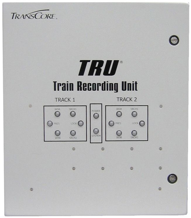
TRU Lights and What They Mean
The TRU continuously performs self-diagnostics while the system is turned on (power light on). The TRU has
LED indicators indicating whether or not the antenna channels are active (Search 1 and Search 2) as well as a
Tag Lock indicator that is lit when a valid tag is seen on either antenna channel. An audible signal device
(buzzer) sounds whenever the Tag Lock indicators are lit. The TRU also has lights indicating controller (system)
status. The front panel LEDs not only indicate that the TRU has power, but also indicate that the wheel detector
segments A and B are receiving signals (WDA and WDB) as a train passes by.
In normal operation, one TRU will be configured to cover one track. In this configuration, the TRU will interface
to one Multiprotocol Rail Reader (MPRR) through the Reader 1 connection on the bottom of the TRU as well as
to the track wheel detector and presence detector via the 16-pin Main Block Phoenix connector. In this
configuration, all LED indications will be seen inside the TRACK 1 block on the front panel of the TRU. The
LED indications are shown in Table 1.
Table 1 TRU Front Panel LEDs - Single Track MPRR (Single MPRR)
Top Panel Lights Default Error Condition What It Means
Power ON OFF TRU is powered up
System ON OFF TRU is operational
TRACK 1 LEDs
Flashing ON Wheel Detector seg-
No flashing during
WDA – Track 1 with wheel ment A signal on Track
wheel detect
detect 1
Flashing ON Wheel Detector seg-
No flashing during
WDB – Track 1 with wheel ment B signal on Track
wheel detect
detect 1
On with track Track 1 presence
PRES – Track 1 Off with track presence
presence detector senses a train
TRACK 1 SRCH AND LOCK LEDs
ON with
Search 1 – Track 1 OFF during Reader 1 Any Reader 1 Antenna
Reader 1 RF
(SRCH1) RF On activated
On
Search 2– Track 1 Not Used with
Not Used with MPRR Not Used with MPRR
(SRCH2) MPRR
ON with
OFF during Reader 1 Any Reader 1 antenna
Tag Lock – Track 1 Reader 1 tag
tag read is reading a tag
read
5ACTIVE LEDs - TRU CONNECTED TO
MPRR VIA READER 1 CONNECTOR
SINGLE TRACK – TRACK 1
LEDs ARE DRIVEN BY LEDs ARE DRIVEN BY
“MAIN BLK TRACK 1” “READER 1” PORT
TRACK 1 TRACK 2
WDA SRCH1 WDA SRCH1
POWER
PRES LOCK PRES LOCK
SYSTEM
WDB SRCH2 WDB SRCH2
MAIN BLK
READER 1
TRACK 1 TRACK 2
DC IN
+ - WDA WDB PRES WDA WDB PRES SPARE
Figure 1 Single Track - Track 1
In certain situations such as slower speed track sites, one TRU may be configured to cover two tracks. In this
configuration, (Figure 1) the TRU will interface to one Multiprotocol Rail Reader (MPRR) through the Reader 1
connection on the bottom of the TRU as well as to the track wheel detectors and presence detectors via the 16-pin
Main Block Phoenix connector. In this configuration, the LED indications for the Track 1 wheel detector and
presence detector will be seen inside the TRACK 1 block on the front panel of the TRU; LED indications for the
Track 2 wheel detector and presence detector will be seen inside the TRACK 2 block.
Note: Since a single MPRR is used in this two track scenario, the TRU will route all RF signals from the MPRR
to the Search 1 (SRCH1) and Lock LEDs in the TRACK 1 block, independent of whether the RF signal is coming
from Track 1 or Track 2. The TRACK 1 SRCH 1 and LOCK LEDs will illuminate for activity on either track. The
TRACK 2 SRCH and LOCK LEDs will not illuminate. These LEDs are for use only with a two-reader AI1200
setup.
The LED indications are shown in Table 2:
6Table 2 TRU Front Panel LEDs - Dual Track MPRR (Single MPRR)
Top Panel Lights Default Error Condition What It Means
Power ON OFF TRU is powered up
System ON OFF TRU is operational
TRACK 1 LEDs
Wheel Detector seg-
Flashing ON with wheel No flashing during wheel
WDA – Track 1 ment A signal on
detect detect
Track 1
Wheel Detector seg-
Flashing ON with wheel No flashing during wheel
WDB – Track 1 ment B signal on
detect detect
Track 1
Track 1 presence
PRES – Track 1 On with track presence Off with track presence detector senses a
train
TRACK 2 LEDs
Wheel Detector seg-
Flashing ON with wheel No flashing during wheel
WDA – Track 2 ment A signal on
detect detect
Track 2
Wheel Detector seg-
Flashing ON with wheel No flashing during wheel
WDB – Track 2 ment B signal on
detect detect
Track 2
Track 2 presence
PRES – Track 2 On with track presence Off with track presence detector senses a
train
SRCH AND LOCK LEDs (TRACK 1 LEDs COVER BOTH TRACKS)
Any Reader
ON with Reader RF On Antenna activated
Search 1 – Track 1 (SRCH1) OFF during Reader RF On
(Track 1 and/or Track 2) (Track 1 and/or
Track 2)
Not Used with
Search 2– Track 1 (SRCH2) Not Used with MPRR Not Used with MPRR
MPRR
Any Reader
ON with Reader valid
OFF during Reader tag antenna is reading a
Tag Lock – Track 1 tag read (Track 1 and/or
read valid tag (Track 1
Track 2)
and/or Track 2)
TRACK 2 SRCH AND LOCK LEDs ARE UNUSED FOR MPRR AND ARE FOR AI1200 USE ONLY
7ACTIVE LEDs - TRU CONNECTED TO
MPRR VIA READER 1 CONNECTOR
DUAL TRACK – TRACK 1 AND 2
LEDs ARE DRIVEN BY LEDs ARE DRIVEN BY
“MAIN BLK TRACK 1” LEDs ARE DRIVEN BY “MAIN BLK TRACK 2”
“READER 1” PORT
TRACK 1 TRACK 2
WDA SRCH1 WDA SRCH1
POWER
PRES LOCK PRES LOCK
SYSTEM
WDB SRCH2 WDB SRCH2
MAIN BLK
READER 1
TRACK 1 TRACK 2
DC IN
+ - WDA WDB PRES WDA WDB PRES SPARE
NOTE: WHEN THE MPRR IS CONNECTED
THROUGH THE “READER 1” PORT, ALL LED
INDICATIONS WILL BE THROUGH THE TRACK 1
SRCH1 AND LOCK LEDs – EVEN IF THE TAGS
BEING READ ARE FROM TRACK 2
Figure 2 Active LEDs - Dual Track - Track 1 and 2
External Interfaces
The TRU interfaces with a Multiprotocol Rail Reader (MPRR) via the 16-pin multi-conductor circular connector
(named Reader 1) on the bottom of the unit. The TRU will in the future also be able to connect to a second
MPRR through the Reader 2 connector (Figure 2).The TRU also is configured with one (1) modem port, four (4)
serial ports and one (1) Ethernet port (Table 3). The Ethernet port is a dedicated port and is always connected and
is the main interface between the TRU and the outside world. The serial ports include auxiliary data ports for
interfacing to peripheral equipment at the site as well as a local bidirectional COM port for direct onsite interface
to the TRU and an output only serial port for monitoring data traffic. The TRU also provides three 16-Pin
Phoenix-type connectors for digital input/output (D I/O) for wheel detector inputs, AC voltage monitor, and track
presence detectors (Table 4).
8Table 3 Communications Ports
Port What It Does
Local Laptop Port for direct onsite laptop connection
CONSOLE
to TRU
Auxiliary serial port for communication between TRU
EXT. RS-232
and external devices
Output only – echo of the main serial data output –
AUX RDR 1
Reader 1
Output only – echo of the main serial data output –
AUX RDR 2
Reader 2
Supports dial up connections using the public
Modem
switched telephone network (PSTN)
10/100Mbps port for connection to a local network or
Ethernet
to other TRU units
Table 4 External Device Ports
Port What It Does
Reader 1 Direct connection to MPRR 1
Reader 2 Direct connection to MPRR 2
MAIN Terminal Inputs from Track 1 and Track 2 – WDA, WDB and Pres-
Block ence; +24VDC in from Battery Charger
AUX Block 1 Auxiliary Inputs 1 through 6 from external devices
Auxiliary outputs 1 through 4 to external devices; Sense
AUX Block 2
Output, +12VDC out
Electrical and Communications Requirements
The TRU operates off the same battery charger-generated voltage (24VDC) as does existing trackside AEI
equipment. Communication to the TRU is via Ethernet (network connection) or by internal modem to the public
telephone system.
Installing the TRU
The TRU is designed to be a direct replacement of existing track-side AEI equipment. As wiring and connectors
are removed from the existing equipment, they will be reconnected to the TRU.
Tools You Will Need
To install the TRU you need standard tools and fasteners for installing the unit on the wall (drill, bolts, wrenches,
etc.), an audible circuit tester, a compatible power/communications cable, and a PC. A laptop using a
terminal emulation program such as Microsoft HyperTerminal can be used for most diagnostic test and TRU
command entry.
Confirm the Following:
Confirm that all necessary pre-existing wiring is accounted for, is in place and is in good working order. Check
external wiring for any kinks, frayed wires or any other defects.
Mounting the TRU
The TRU will normally be placed in the spot where the existing AEI equipment was removed.
9To mount the TRU
1. Using the back of the TRU as a guide, mark the placement of the four (4) mounting holes.
2. Drill the mounting holes and mount the TRU
Once the hole placement is determined, use a 3/8 in drill bit to drill four (4) holes for mounting the TRU.
Mount the TRU by screwing it directly to the existing plate using 3/8 inch bolts or screws.
Connecting the Multiprotocol Rail Reader(s)
Caution
Before making any connections between the TRU and the MPRR, verify that the MPRR is con-
nected to the external antennas via its N-type connectors. Failure to verify this connection may
result in damage to the MPRR.
To connect the MPRR
1. Verify that the MPRR is connected to the appropriate track-side antennas via coaxial cable.
2. Connect the MPRR to the TRU Reader 1 port using the supplied TRU-to-MPRR cable.
Connecting Power
The TRU uses the existing +24VDC power as wired from the +24V battery charger output.
To connect the power
1. Connect the cable as follows:
MAIN Block Pin 1: +24VDC in
MAIN Block Pin 2: +24VDC return
2. Power up the TRU and confirm that the front panel POWER and SYSTEM LEDs are on (green). It may
take a couple of minutes for the SYSTEM light to come on.
Refer to the TRU Installation Manual for all subsequent power and range sensitivity adjustments.
Connecting the Wheel Detector Segments
During passage of a train over the TRU site, the system uses information from the wheel detectors to recognize
the presence of a car or a locomotive, and discriminate between various types of equipment. For wheel detection,
the TRU uses the Tiefenbach G84/97/24 wheel detector amplifier, connected to the MAIN Terminal Block.
To connect the G84/97/24 wheel detector amplifier:
1. Connect the cable as follows:
• MAIN Block Pin 3: WDA+ wheel detector input
• MAIN Block Pin 4: WDA- wheel detector input
• MAIN Block Pin 5: WDB+ wheel detector input
• MAIN Block Pin 6: WDB- wheel detector input
2. Once powered up, amber LEDs on each designated wheel detector input channel of the G84 will come on,
showing that the selected channel is operational.
To test the TRU Wheel Detector LEDs (Track 1/Reader 1)
1. With the TRU turned on, lay a coin on the SII side of the Tiefenbach wheel detector transducer. The WDA+
output channel LED on the G84 amplifier and the Track 1 WDA LED on the TRU should light.
2. Remove the coin. The Track 1 WDA LEDs on the TRU and G84 amplifier will extinguish.
103. Lay a coin on the SI side of the wheel detector transducer. The WDB+ output channel LED on the G84
amplifier and the Track 1 WDB LED on the TRU should light.
4. Remove the coin as in step 2 and verify that the LEDs go off.
For Track 2/Reader 2 (if installed), repeat steps 1-4 for that track.
Connecting and Testing the Presence Loop
The AEI system can provide a digital input consisting of an active “low” (GND) on a designated terminal to
indicate a train presence to the TRU. The TRU begins to collect data for a train as soon as the presence detector
indicates that a train is present or a wheel detector indicates that a wheel has been detected. The TRU determines
that a train is no longer present when the presence detector indicates that a train is no longer present (GND
removed), or after a configurable amount of time has passed with no new wheel detector data, if there is no input
from a presence detector.
To connect the presence detector (loop type)
1. Connect the cable as follows:
• MAIN Block Pin 7: PRES IN presence detector input
• MAIN Block Pin 8: GND Chassis Ground
To test the loop using standard digital loop detectors
1. Set the loop detector to a sensitivity value of “9” and lay a large piece of metal on the track loop wire. The
LED on the loop detector and the TRU Search LEDs should light indicating train presence.
2. Remove the metal piece. The LEDs should turn off indicating that train presence has cleared
3. Reset the loop detector sensitivity to “1” for normal operation.
Connecting Communications
The TRU supports both remote and local communications.
Ethernet Connection/Telephone Line
The TRU has an Ethernet port for connection to a local network. This is the preferred method of communicating
between the TRU and the back office. For existing land line AEI installations, the TRU also has a Modem port
for connection of a standard RJ-11 telephone line. In these cases, installation is simply to connect the existing
phone line into the TRU.
To test the telephone line
Dial the TRU phone number using a modem and communications packages that supports ANSI terminal.
Local Communications
For local communications (direct to a laptop computer) the TRU has a bi-directional serial COM port designated
“CONSOLE”. Using a laptop, the technician can access the TRU user interface in real time. This port is a nine
(9) pin “D” type connector.
Correct Grounding
The TRU is designed to be installed in the existing track-side HUT and uses the existing earth ground resident in
the HUT. The TRU has grounding lugs and loops for this purpose. Ground the TRU following the recommended
grounding shown in Figure 3. The actual HUT at a specific site may differ from this illustration.
11GND to
To MPRR Ant
TRU
0 and 1
Surge Protection
Block
Antenna COAX
Cable
36in Copper wire
grounding pigtails
Grounding
wire
Ground
Antenna Signals
Rod
Power in to
Hut
Figure 3 Grounding Diagram
Figure 4 depicts a typical HUT exterior.
PTM W In fo etc...
94"
6' (72")
Figure 4 TRU Track-side Hut Exterior
12Figure 5 shows the interior of a typical HUT.
TRU Mounting Plate
MPRR TRU Network Interface
Surge Protection
Power conditioning circuitry
Block Battery next to battery charger
Reader IF Cable Charger
Phone Line out
36in Copper wire grounding
Antenna COAX Cable pigtails
Power in to
Hut
Wheel Detector and Loop signals
Antenna Signals
Figure 5 TRU Trackside Hut Interior
Figure 6 provides an interface wiring diagram for the TRU.
W DA - W DB +
W he el De tec to r A W DA + W DB - W hee l De te ctor B Ph on e Lin e
+2 4V D C R T N P re se nc e IN
+2 4V D C F r om P ow er + 24V D C IN G ND P r es en ce D ete ctor
D istrib ution P a ne l
TR U
kc ar T SE1RP
kc ar T SE2RP
1W
1W
2W
2W
AD
BD
AD
BD
REA DE R 1
NI CD
kc ar T
kc ar T
kc ar T
kc ar T
AUX R DR 1 M O DE M
AU X R D R 2
1
2
3
4
5
6
t upnI
t upnI
t upnI
t upnI
t upnI
t upnI
R E AD ER 2 E THE RN E T
C O N S O LE
1
2
3
4
2CDV
T UO C+5V
t upt u O
t upt u O
t upt u O
t upt u O
D
T UO+1
E XT RS -2 32
To M PR R 1 To M P R R 2 L oc al P or t E ther ne t P or t
Figure 6 TRU Interface Wiring Diagram
13Accessing the TRU User Interface Main Menu
The following describes the steps to communicate with the TRU User Interface.
1. Connect a laptop computer to the TRU via the CONSOLE port and start the terminal emulation application
Microsoft HyperTerminal or equivalent.
In the dialog boxes choose the com port to which the communications interface is attached and set the
properties as follows:
• Bits per second: 9600 baud
• Data bits: 8
• Parity: None
• Stop bits: 1
• Flow control: None
2. Power up the TRU and verify reader sign-on message appears on laptop/computer display.
3. Once the TRU has been wired up and turned on (with the laptop connected to the CONSOLE port), a sign-
on message will appear signifying that the reader is talking to the laptop.
4. At the login prompt enter your Username and Password.
5. For access to all of the menus within the Main Menu you will need to login as a Super-level user. To login
as a Super level user type in Username: super1 and Password: Super1. Letter case is important.
6. At this point, you can enter commands into the reader for testing, set up, and tuning.
7. Input proper commands in order to access the TRU.
8. The TRUs Main Menu consists of four user commands (1 – 4) and two navigation commands; “X” and
“CMD?” (Figure 7).
Figure 7 TRU Main Menu
14Entering the Site Maintenance Menu (SITEMNT)
The Site Maintenance Menu is entered from the Main Menu by either typing “SITEMNT” or the number “1”.
This command, as well as many others, is also accessible from any other menu when typed out.
Table 5 Testing Commands
Enter Reader Response What It Does
Takes the user to the System Maintenance Menu
SITEMNT or “1” Site Maintenance Menu (SYSMNT) and Device Maintenance Menu
(DEVMNT)
Allows the user to Simulate a Train (SIMTRN),
SYSMNT. System Maintenance Menu Backup and Restore Data (BACKUP, RESTORE)
and Reboot the TRU (RBUNIT)
Allows the user to initialize the MPRR (IR), turn
RF on (RFON), fire the antenna check tag
(CTSEQ), toggle sensor power (TGPOWR) and
DEVMNT Device Maintenance Menu
self test the modem (MDMSTST). The user can
also input and monitor MPRR commands in real
time (PAS2RDR)
Configuration Menu (CONFIG)
The Configuration Menu is entered from the Main Menu by either typing “CONFIG” or the number “3”. This
command, as well as many others, is also accessible from any other menu when typed out.
Use TRU commands to query status and set up the system as shown in the following table:
15Table 6 Commands Used in System Configuration
Command Description What It Does
Allows the user to configure tenant parameters
CONFIG OR “3” Configuration Menu (TNTPRM) as well as site parameters for each
tenant (SITEPRM)
Allows the user access to site information
Tenant Parameters (SITEINFO) as well as access to AEI
TNTPRM
Menu (AEIRPTO) and maintenance (MNTRPTO)
report options
Includes site name (TSITENAME), owner ID
(OWNERID), station number and milepost
Site Information
SITEINFO (STNUM, MILPOST), railroad initials (RRINI),
Parameters
track designation, orientation and direction
(TRKDSGN, TRKORIENT, TRKDIRECT)
AEI Report Options Includes direction report, minimum axle and car
AEIRPTO
Menu count, and tag read confidence levels
Maintenance Report Enables the maintenance report as well as sets
NMTRPTO
Options Menu report parameters
Allows access to the site administration menu
(SITEADM), the track configuration menu
SITEPRM Site Parameters Menu
(TRKCONFIG) and Reader/Antenna configura-
tion menu (RDR)
Allows editing of the site primary and secondary
phone numbers (PPHNUM, SPHNUM) and pri-
mary and secondary IP addresses (PIP, SIP).
Site Administration
SITEADM Allows the creation of and access to the user
Menu
(UMAINT), track (TRKMAINT) and tenant
(TENMAINT) maintenance menus for password
and user ID maintenance
Allows creation, editing or deletion of user infor-
User Maintenance
UMAINT mation including user Name, Password, Privi-
Menu
lege and Status
Allows listing of tracks to tenant, allows adding
Track Maintenance
TRKMAINT a tenant to a track or deleting a tenant from a
Menu
track
Allows creation, editing or deletion of a tenant.
Tenant Maintenance
TENMAINT The local time menu and consist report defini-
Menu
tion is also in this menu.
Allows access to the menus that control the
acquisition of wheel and tag events; the operat-
Track Configuration ing menu (OPERATE), the auxiliary device
TRKCONFIG
Menu menu (AUXDEV), wheel detector menu (WDE-
TECT), presence loop menu (PRLOOP), and
antenna menu (ANTENNA)
Includes wheel detector orientation and separa-
tion (WDORNT, WDSEPAR), external presence
OPERATE Operating Menu override (PRESEOV), presence timeout
(PRESTO), minimum wheel events (MAXW-
EVT) and stopped axle distance (STOPAXD)
16Displays the valid parameters for the selected
com port; baud rate (AUXBAUD), word length
AUXDEV Auxiliary Device Menu (AUXWORDLEN), stop bits (AUXSTOPBIT),
parity (AUXPARITY) and flow control (AUX-
FLOWCTL)
Controls the way presence, speed and direction
WDETECT Wheel Detector Menu
are detected by the wheel detectors
PRLOOP Presence Loop Menu Controls the presence loop performance.
Controls values that control antenna perfor-
ANTENNA Antenna Menu
mance
Lists the valid readers for which parameters
Reader Selection may be viewed or edited. This menu allows
RDR
Menu enabling of the reader and antennas for each
assigned track.
Reports Menu (RPTS)
The Reports Menu is entered from the Main Menu by either typing “RPTS” or the number “4”. This command,
as well as many others, is also accessible from any other menu when typed out.
1.Use TRU commands to view reports as shown in Table 7:
17Table 7 Commands Used to Generate and View Reports
Command Description What It Does
Provides access to TRU system summary reports
RPTS or “4” Reports Menu (SYSRPTS) or train reports (TRNRPTS)
Allows the user to check software system manag-
ers (MGRSTAT), directory listings (DIRLST), file
SYSRPTS System Reports Menu
types (TYPE), system health (HEALTH) and Status
Monitor information (IO) for a selected tenant
System Status Informa- Displays the status of each embedded manager
MGRSTAT
tion and reports if the manager is not running
DIRLST Directory Listing Displays the contents of a specified directory
TYPE Display Contents of File Displays the contents of a specific file on the TRU
Displays any trains flagged by the TRU as having
potential problems. Displays hardware related
HEALTH System Health Summary
warning and failure messages written during the
recording of trains.
Displays status of the Input/Output (I/O) pins in real
time. Information displayed includes train and track
presence, wheel detector detection, RF ON, train
IO Status Monitor
direction of travel, sensor power on, reader power
on, AC Power status, tag activity and adjacent track
status.
The Audit Log screen displays tenant and site
AUDIT Display Audit Log Info parameters whose configuration has been changed
through the MUI.
Tenant specific menu including train directory
(DIRECT), Dump Data Summary (DDSUM), Dump
TRNRPTS Train Reports Menu Data Full (DDFULL), S918A Clean Consist
(CCNSS918A), Train Summary (TRNSUM) and
Train Events (TRNLOG).
Shows the most current trains that have passed by
the site. The number of trains is user selectable.
Directory includes train sequence number, date and
DIRECT Train Directory time of passage, whether the train was okay, identi-
fies the lead locomotive, indicates direction, speed,
number of axles, number of railcars, number of tags
and train length.
Summarizes the raw train data into axle and speed
Dump Data Processing summaries, axle and tag correlation to recognized
DDSUM
Summary railcar summary, tagged equipment summary and
reader handshake summary by antenna.
Summarizes the raw train data into tag specific and
non-tag specific information for each car on the
train. Includes the site information header, train
Dump Data Full Com- summary and detail headers as well as the com-
DDFULL
posite Listing posite AEI listing for all recorded cars in the train.
Listing information includes car number, EGC, car
IDs, A or B side lead in, number of axles and plat-
forms, length, speed and tag data for each car.
18Summarizes the train data into the generic format
of a clean consist. Includes the site information
Clean Consist – Generic header, train summary and detail headers as well
CCNSGEN
Format as the generic consist information. Information
includes EGC, car number (location in train), car ID,
direction and number of handshakes for both tags.
Displays the train consist data in the Full Consist
format. Includes the site information header, train
summary and detail headers as well as the Full
Clean Consist – Full
CCNSFULL Consist information. Information includes car num-
Consist Format
ber (location in train), EGC, car ID, tag status, A or
B side lead in, axle count, length, speed, platform
count and tag handshake data for each car.
Displays the train data in the S918A format as
defined by the AAR AEI Site-To-Host Consist For-
mat Standard S918A. Includes the site information
Clean Consist – S918A header, train summary and detail headers as well
CCNSS918A
Format as the S918A consist information. The consist
information begins with the AEM heading and con-
tains railroad-specific fields including (but not lim-
ited to) RRE, RTD, EOT, etc.
Displays the site information header, train summary
TRNSUM Train Summary and detail headers but without the consist informa-
tion.
Displays hardware related maintenance messages
written during the recording of a specific train.
TRNLOG Train Events
Includes warning and failure messages which may
affect the consist.
Displays maintenance messages written during the
Consist Host Transac-
TRNLOGCNS process of uploading a specific train consist to the
tion Events
host.
Displays maintenance messages written during the
Maintenance Host
TRNLOGMNT process of uploading maintenance reports around
Transaction Events
the time of a specific train.
19S P E C I F I C A T I O N S
TransCore
Train Recording Unit
(TRU)
System
Two easy ways to contact us:
Call Technical Support at 505.856.8007
Visit us on the Web at www.transcore.com
TransCore
8600 Jefferson Street NE
Albuquerque, NM 87113
www.transcore.com
©2014. TransCore LP. All rights reserved. TRANSCORE is a registered trademark and is used under license. All other trademarks are the property of their respective owners.
Contents are subject to change. Printed in the U.S.A.
16-0013--001 REV AYou can also read