Project Management and Software Development for Medical Applications
←
→
Page content transcription
If your browser does not render page correctly, please read the page content below
Lab Course / Praktikum
Project Management and Software Development for
Medical Applications

UML: Unified Modeling Language – 03/11/2020
Winter Semester 2020/21

Conducted by:
Ardit Ramadani, Zhongliang Jiang, Tianyu Song, Lennart Bastian
Slides by: Farid Azampour
Agenda

Part 1
   Software Design
   What is UML?
   Class Diagrams
   Use Case Diagrams

Short break (if needed)

Part 2
   Component Diagrams
   Sequence Diagrams
   Activity Diagrams
   UML Tools

          Computer Aided Medical Procedures   April 13, 2021   Slide 2
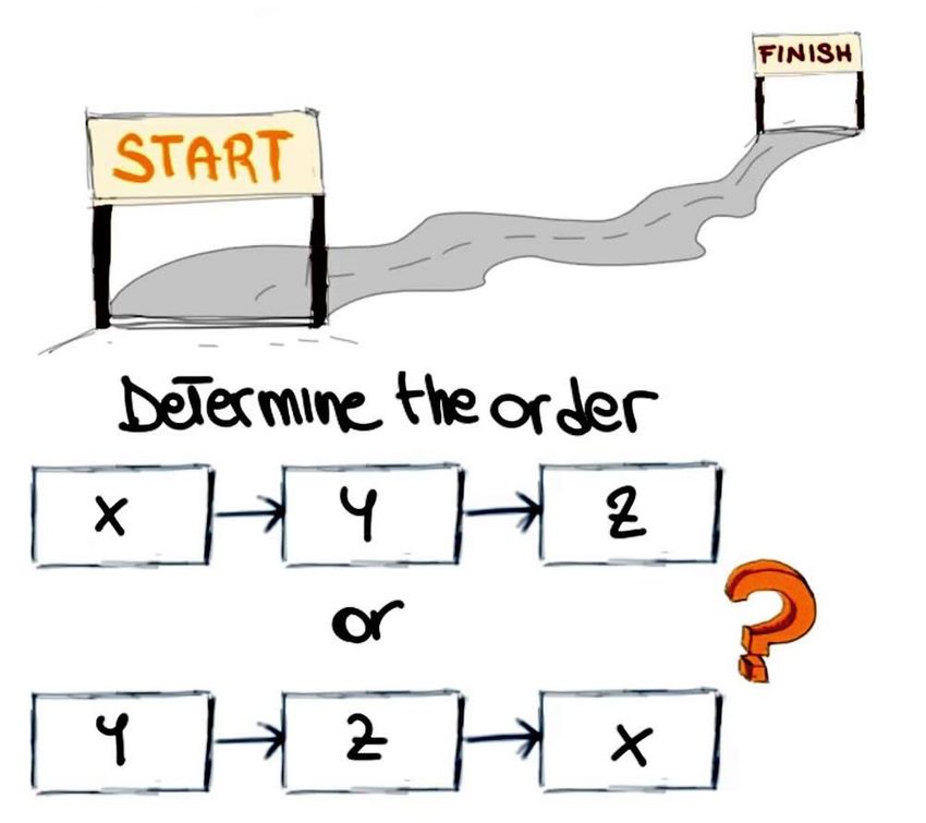
QUIZ TIME!

                                    Each chapter will be followed by some questions to be discussed by the students.

Computer Aided Medical Procedures                                                                                      Slide 3April 13, 2021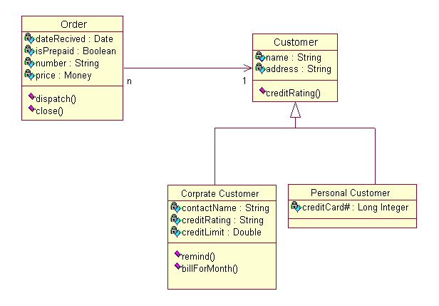
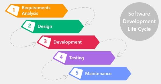
Software Development Life Cycle

       Computer Aided Medical Procedures   April 13, 2021   Slide 4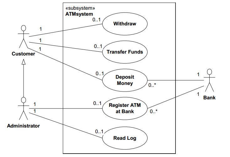
Software Development Life Cycle

                                     Software Design is about modeling software systems

       Computer Aided Medical Procedures                                                  April 13, 2021   Slide 5
The Importance of Modeling
• A model is a simplification of reality.
• We build models so we can better understand the system we are developing
Benefits:
• Visualization:
– Improves the productivity of the development team
– Permits early exploration of alternatives
• Behavior and Structure:
– Improves the understanding of the system
• System Template:
– Reduces the number of defects in the final code
– Increases the decomposition and modularization of the system
– Facilitates the system’s evolution and maintenance
• Documentation
Computer Aided Medical Procedures April 13, 2021 Slide 6Visuals Help in Software Design
Clients/stakeholders Programmers Analyzers
Computer Aided Medical Procedures April 13, 2021 Slide 7Unified Modeling Language (UML)…
… is an industry standard for visualizing, specifying, constructing, and documenting the artifacts of a
software system.
… is not for the sake of creating diagrams, however…
... it is about creating a model which you visualize in a diagram
according to the de facto standard modeling language.
… is extended and updated over time:
1996 UML 1.0
2005 UML 2.0
2009 UML 2.2
2015 UML 2.5
2017 UML 2.5.1
https://www.omg.org/spec/UML/
Computer Aided Medical Procedures April 13, 2021 Slide 8UML Is a Formal Visual Language
• UML offers a framework for deriving simplified models of a complex reality
• UML is a graphics-based language with syntax and semantics
– Every valid structure has a meaning (semantics)
– There are rules defining how structures may be put together (syntax)
– Programming platform independent
• UML is a great communication tool
– Natural language is often imprecise and source code too detailed
– It standardizes a very natural, visual communication approach: drawings
– UML moves us from fragmentation to standardization while offering flexibility
Computer Aided Medical Procedures April 13, 2021 Slide 9Structure and Behavior Are The Main Two UML Types
Meta: UML diagram of
available UML
diagrams
What things are What’s the
needed and how are functionality and how
they connected? is it achieved?
Computer Aided Medical Procedures April 13, 2021 Slide 10QUIZ TIME! 1. In which phase of the Software Development Cycle are UML diagrams mainly created? 2. Name two benefits of software models! 3. How would you define UML in your own words? 4. What is the difference between Structure and Behavior Diagrams?
Class Diagram - Introduction

• Is a static structure diagram based on classes
• No logic or functionality included
• Probably the most popular and most used diagram type
   – Still UML diagram != UML class diagram
   – INSTEAD: Planning should start with other diagrams!

• Consists of                                                          Person
                                                                                                         Address
                                                                                                     Street : String
   1. Classes: attributes, operations or methods       Name : String
                                                                                                     Zip : String
                                                       Address : Address
                                                                                                     City : String
   2. Relationships among the classes.                 changeAddress(in newAddress : Address)        Country : String
                                                                                                     print()

         Computer Aided Medical Procedures                                                      April 13, 2021     Slide 12
Class Diagram – Syntax
Visibility:
+ public
- private Name
# protected
/ derived “+ AttributeName : TypeName [*]” Attributes
Methods contain: Methods/
• Parameters(and Operations
default values)
• Accessibility:
e.g. static
Can have different levels of detail!! Car
Name Italic if abstract
Computer Aided Medical Procedures April 13, 2021 Slide 13Class Diagram - Relationships
Class
Composition
Association
Dependency
Generalization
Aggregation
Interface «interface»
Adorable
Multiplicity: How many objects can participate in the relationship.
Realization Indicates the number of instances of one class linked to instances of
Puppy the other class.
0 or more: *
1 or more 1..*
From 2 to 4: 2..4
Only 7: 7
Computer Aided Medical Procedures April 13, 2021 Slide 14Class Diagram - Dependencies
• Means that one class makes use of another class at some point in time
• Can be read as “… needs a …” or “… uses a …”
• Weakest form of relation after “no relation”
• Typically used if the independent class is a parameter of an operation of the
dependent class
• Stereotypes are commonly used to highlight the precise nature of a dependency, e.g.
, ,
IceCreamVendor
Cone
+scoopIceIntoCone(inout Cone c)
scoopIceIntoCone
needs a Cone
Computer Aided Medical Procedures April 13, 2021 Slide 15Class Diagram - Associations
• Stronger relationship than dependencies
• Implies that two classes are coupled over a long period of time
• Can be read as “… has a …” or “… knows of …”
• Typically used if one class has an attribute with a type of another class
Student Course Bidirectional association implies
that both Student and Course
0..* 1 -registeredStudents : List
are aware of the association.
• Associations can be unidirectional to indicate navigability
All relationships may
have a name
watches
PoliceOfficer Thief
Computer Aided Medical Procedures April 13, 2021 Slide 16Class Diagram - Composition and Aggregation
• Both aggregation and composition represent a whole-part relationship
• The main difference is how dependent the “part” is on the “whole”
• Aggregation: parts do not depend on lifecycle of the whole
Pond If the pond dries Team No player dies
out the duck still just because the
exists. AnotherTeam
team dissolves.
Also, players can
be shared.
Duck Player
• Composition: parts depend on the lifecycle of the whole, they are “owned”
Building Human
If the building
is demolished, Human body parts
the room is too. cannot exist on their
own. Also, they cannot
Room Organ Leg be shared.
Computer Aided Medical Procedures April 13, 2021 Slide 17Class Diagram – Generalization/Specialization
• Used to show inheritance
• Reads as “… is a …”
Computer Aided Medical Procedures April 13, 2021 Slide 18Class Diagram - Summary
CourseSchedule Course
Body Arm
Student
Person Professor
Employee
University Student
Computer Aided Medical Procedures April 13, 2021 Slide 19QUIZ TIME! 1. Define Class Diagrams in your own words! 2. What are the main components of a Class Diagram? 3. Does a Class Diagram describe a static or dynamic view of a software system? 4. Explain the difference between Aggregation and Composition!
Quiz Time cont.

    University                       Student

  Which statements are true?

  5. "Student" is part of "University".

  6. If an instance of "University" is deleted, all contained
  instances of "Student" are also deleted.

  7. If an instance of "University" is deleted, the contained
  instances of "Student" are not affected.

  8. "University" is part of "Student".

  9. If an instance of "Student" is deleted, all contained
  instances of "University" are also deleted.

            Computer Aided Medical Procedures                   April 13, 2021   Slide 21
Quiz Time cont.
University Student
Which statements are true?
5. "Student" is part of "University". ✔
6. If an instance of "University" is deleted, all contained
instances of "Student" are also deleted. ✖
7. If an instance of "University" is deleted, the contained
instances of "Student" are not affected. ✔
8. "University" is part of "Student". ✖
9. If an instance of "Student" is deleted, all contained
instances of "University" are also deleted. ✖
Computer Aided Medical Procedures April 13, 2021 Slide 22Use Case Diagram
• A use case diagram shows the functionality of a system
– “What can a system do?”, not “How does it do it?”
• It consists of named entities of functionality (use cases) and entities triggering the use cases or
receiving their output (actors)
• Very important for requirements analysis: Identify all users and functionalities
ATM
Check Balance
Withdraw Money
Bank Account Owner
Use case outside of
system boundary
Spend Money
Computer Aided Medical Procedures April 13, 2021 Slide 23Elements of Use Case Diagrams (I/II)
• Actors
– Humans or external systems, interacting with the system
– Often custom representations are used
Student
Enroll in • Use cases
university
– A piece of functionality, provided by the system
– Best practice for naming: [action verb] + [object]
• E.g. “place order”, “invite attendees”, “pay invoice”
– Use cases do not describe the process (the single steps) of how this interaction takes place, this might be
documented within the use case description.
• Actor/Use Case Association
– Indicates that the actor initiates a use case or receives results from the use case, or both directionality optional
1 *
– May show multiplicities
– No Actor/Actor associations!
Computer Aided Medical Procedures April 13, 2021 Slide 24Elements of Use Case Diagrams (II/II)
• System boundaries
Amazing Software – Box with name, use cases inside box, actors outside box
System
– Yet, showing use cases outside your system can be useful
• Use Case Extension
– Indicates additional functionality on top of a base use case
– Base use case is complete use case on its own
• Use Case Inclusion
– Indicates that base use case is not complete on its own but includes one or more other use cases
– Used to group smaller use cases into a large one or to factor out common functionality that is included by
several use cases
• Generalizations (Actor/Actor or Use Case/Use Case)
• Comments
Computer Aided Medical Procedures April 13, 2021 Slide 25Use Case Diagram Example: Online Shopping System
Online Shopping System boundary
Association
Create Account
Use case
Generalization
Browse Items
New Customer
Use case inclusion
«includes»
Web Visitor
Make Purchase Actor
Registered Customer «includes»
Checkout
Payment Processor
Computer Aided Medical Procedures April 13, 2021 Slide 26Use-Case Diagram Example: Multiplicities
From the UML Superstructure Specification
Computer Aided Medical Procedures April 13, 2021 Slide 27QUIZ TIME! 1. Describe the Use Case Diagram in your own words! 2. Which of the following statements correctly characterize use cases? a) Use cases can be derived from the clients' requests. b) Use cases specify the procedural process within a system. c) Use cases specify the functionalities that the system should have. d) Use cases are suitable for modeling interfaces between two systems.
Quiz Time cont.

Which of the following use cases are correct use cases when you want to design a use case diagram for an online book
shop?
3. Look for a book

4. Cancel order

5. Do not order a book

6. Login

7. Enter book title

8. Order a book

9. Enter credit card details

           Computer Aided Medical Procedures                                                     April 13, 2021   Slide 29
Quiz Time cont.
Which of the following use cases are correct use cases when you want to design a use case diagram for an online book
shop?
3. Look for a book ✔
4. Cancel order ✔
5. Do not order a book ✖
6. Login ✖
7. Enter book title ✖
8. Order a book ✔
9. Enter credit card details ✖
N.B.: Use cases do not describe the single steps of how this interaction takes place. A user will not just enter his credit card details; this might be one single step within the use case “Order a book”.
Computer Aided Medical Procedures April 13, 2021 Slide 30Structure and Behavior Are The Main Two UML Types
Meta: UML diagram of
available UML
diagrams
What things are What’s the
needed and how are functionality and how
they connected? is it achieved?
Computer Aided Medical Procedures April 13, 2021 Slide 31Component Diagram
• Show the structural relationships between the components of a system (higher level than class
diagram).
• Very easy type of diagram, related to class diagram
• Components are highly cohesive and encapsulated high-level design units (“black boxes”).
– Often components are classes but not necessarily
• The communication is through interfaces with the inputs required and services provided.
• Can be used independent of OO programming languages
“Half circle”, “socket”:
Provided Interface 1 needed/consumed service
Component Required Interface 1
Provided Interface 2
Computer Aided Medical Procedures April 13, 2021 Slide 32Component Diagram - Examples
“Ball-and-socket“
wiring
Weather Forecast
WeatherService WeatherView
Wiring using dependency
connector is equivalent
Weather Forecast
WeatherService WeatherView
Computer Aided Medical Procedures April 13, 2021 Slide 33More complex example for Component Diagrams
http://www.uml-diagrams.org/component-diagrams.html
Computer Aided Medical Procedures April 13, 2021 Slide 34QUIZ TIME! 1. Are Component Diagrams Behaviour or Structure Diagrams? 2. What are Component Diagrams used for? 3. Name two examples for components!
Sequence Diagram

•   Is an interaction diagram                                       Customer                  ATM                        Bank
     – Models interaction of entities in a system with each other
                                                                               insert(card)

                                                                               requestPIN
•   Typically used to show system behavior and model the                       enter(PIN)
    logic in a specific use case                                                                    isValid(PIN, card)

     – “How?” not “What?”
                                                                                                          valid

                                                                           chooseOption
•   The horizontal dimension shows the objects                           withdraw(amount)
                                                                                                verifyTX(amount, card)
    participating in the interaction
                                                                                                        verified
•   The vertical dimension shows messages in their relative               dispense(amount)

    order                                                                 collect(amount)
                                                                                               confirmTX(amount, card)

           Computer Aided Medical Procedures                                                            April 13, 2021      Slide 36
Sequence Diagram - Elements
Interaction participant
• Objects (interaction participants) with lifeline
• Notation in software engineering: “Name:Type”
• Show how long object is in existence
• Can explicitly put an “x” at the end to highlight destruction
• Activation blocks/bars (formally “Execution specification”) Call
• Participant is sending, waiting, in general: busy
Activation block
• Messages (synchronous, asynchronous, return)
Return
• Synchronous, caller blocks getScore():Integer
orderItem("Frisbee")
• Asynchronous, caller does not block
Lifeline
Return
• Return
• General notation “Name(Parameters):ReturnType”
Computer Aided Medical Procedures April 13, 2021 Slide 37Sequence Diagram - Examples
Object1 Object2
Message Messages can be
WebInterface AccountManagement DatabaseAdapter delayed.
This can also lead
Response to messages being
createNewAccount received out of order.
putUserDocument
Customer Employee
Return
{User document successfuly stored}
Success buy(Alcohol)
idRequired
Overlapping
activation bars show(id)
finishCheckout
State invariant needs to be
true for the rest of the inter-
action to be valid.
Executions may overlap.
Computer Aided Medical Procedures April 13, 2021 Slide 38QUIZ TIME! Which of the following statements are true? 1. A Sequence Diagram can depict the interaction of a system with its surroundings. 2. The vertical axis is called interaction axis. 3. With asynchronous communication the sender does wait for an answer from the receiver. 4. Within Sequence Diagrams time is no separate dimension.
Quiz Time cont.
Which traces are possible for the given Sequence Diagram?

5. D → C → B → A

6. D → A → B → C

7. D → A → C → B

8. A → D → C → B

           Computer Aided Medical Procedures                April 13, 2021   Slide 40
Quiz Time cont.
Which traces are possible for the given Sequence Diagram?
5. D → C → B → A ✖
6. D → A → B → C ✖
7. D → A → C → B ✔
8. A → D → C → B ✔
Computer Aided Medical Procedures April 13, 2021 Slide 41Activity Diagram
• Models execution and behavior / workflow of a system, not its structure
• Widely applicable to any kind of process modeling
• An activity is described by the actions and objects involved and the flow between them, not the
components and their communications
• Elements of activity diagrams Activity
End node (control
flow final node)
– Activity Start node
Partition
– Actions Control flow
– Control or object flows Partition
End node (activity
– Decisions and Merges final node)
Action Action
– Forks and joins
Edge guard Fork node
– Start and end node
– Partitions
… Join node
Decision node
Computer Aided Medical Procedures April 13, 2021 Slide 42Activity Diagram: Activities, Actions and Transitions
• An activity is a sequence of actions and displayed using round-cornered rectangles that contain all
elements of the activity
• An action is a single step within an activity and displayed using round-cornered rectangles
Activity
Drive a car
• Edges can have names and/or guards
– A guard is a condition evaluated at runtime to determine if the edge can be traversed
– Always put guards at decision nodes
Guard
[invoice paid]
Send Invoice Ship Item
Computer Aided Medical Procedures April 13, 2021 Slide 43Activity Diagram: Object Nodes and Object States
• Object nodes are used to model the flow of objects Fill Order Review Order
Object flow Order
Object node
• Activity edges
{weight = 50}
Weight indicates how many
tokens must be available before
Fill Order Order Batch Review Orders
the tokens are presented to
the target action.
Edge weight
• Object states can be indicated by adding qualifiers to object nodes
Order Order
Fill Order Review Order
(Unchecked) (Reviewed)
Computer Aided Medical Procedures April 13, 2021 Slide 44Activity Diagram: Object Decision Nodes
• Can divert and merge the flow
– Only one outgoing edge can be traversed by each control token
• Guards at the branches define how the flow continues
– Only one guard should evaluate to true to avoid race conditions
• Merging does not synchronize multiple concurrent flows
[light: green]
Approach traffic light Drive on
[light: red] [light: green]
Wait
[light: red]
Computer Aided Medical Procedures April 13, 2021 Slide 45Activity Diagram: Forks and Joins
• Forks divide the flow unconditionally into multiple concurrent flows
• Joins synchronize multiple flows and continue once all flows are merged
• Joins can be conditional
{numWorkers >=
numWorkersRequired}
Join condition
Build frame
Fit engine in frame
Build engine
Computer Aided Medical Procedures April 13, 2021 Slide 46Activity Diagram: Exception Handler
• Especially important when describing the workflow of a software system
• An exception is an error that occurs during the execution of an action
• An exception handler protects an action from a specific type of exception by catching the exception
• If not caught, exceptions propagate
Load Image Segment Image
Lightning-bolt-style
Alert User
edge with label
indicating the type of
exception
Computer Aided Medical Procedures April 13, 2021 Slide 47Partitions
• Partitions are a grouping mechanism
• They can be used to visualize responsibilities
Computer Aided Medical Procedures April 13, 2021 Slide 48QUIZ TIME! 1. Can there be more than one activity final node in an Activity Diagram? 2. Which of the following nodes are elements of an Activity Diagram? a) distribution node b) fork node c) decision node d) communication node e) join node
QUIZ TIME! 1. Can there be more than one activity final node in an Activity Diagram? 2. Which of the following nodes are elements of an Activity Diagram? a) distribution node b) fork node c) decision node d) communication node e) join node 3. What is a fork node in an Activity Diagram?
There are many UML tools

•   First iteration during initial design: By hand

•   ArgoUML (http://argouml.tigris.org)
•   Dia (http://live.gnome.org/Dia)
•   Modelio (http://www.modelio.org)
•   Microsoft Visio (available for students through www.studisoft.de)
     –   Be sure to check out supplementary UML stencils: http://www.softwarestencils.com/uml/index.html
•   MySQL Workbench
•   yED (http://www.yworks.com/en/products_yed_about.html)
•   IDEs like Visual Studio, Eclipse and NetBeans often offer UML functionality (directly or through plugins)
•   Actually there are hundreds of tools available – a good start is on wiki:
    http://en.wikipedia.org/wiki/List_of_UML_tools

            Computer Aided Medical Procedures                                                              April 13, 2021   Slide 51
Summary
• UML is a visual modeling language that eases communication about
legacy as well as new (software) systems
– Use it for the requirements analysis and for designing your implementation
• Class and component diagrams are structural diagrams
– Start designing your implementation by drawing a component diagram
– Afterwards, and in case you are using OOP, draw a more detailed class diagram
• Use case diagrams are behavioral diagrams that show the functionality
your system provides on a high level
– Use them while defining the functionality of your software project
– Use them to quickly communicate what your system is capable of (e.g. here in class)
Computer Aided Medical Procedures April 13, 2021 Slide 52Summary
• Sequence diagrams are behavioral diagrams that show how
functionality of your system is realized by visualizing
detailed communication flows between the components
involved
– Use them to show the inner workings of your system that make a use
case (functionality) possible
– Good for showing detailed logic
• Activity diagrams are behavioral diagrams that capture how
a functionality is executed in terms of subsequent actions
– Use them to show how a use case is realized by a series of simple steps
– Good for showing logic of your system without exposing too many
technical details
Computer Aided Medical Procedures April 13, 2021 Slide 53Nota Bene
We do expect you to show us (at least) one UML diagram of your choice
in the kick-of and intermediate presentation!
• Usually recommended* for kick-off: Use Case Diagram "What functionality should my application offer? Who are
the actors?"
• Usually recommended* for intermediate: Class Diagram or Sequence Diagram for more detailed visualization for
your design choices
• Do not mix the UML diagram types and stick to the rules
* Of course this is heavily depending on your individual project and application.
Computer Aided Medical Procedures April 13, 2021 Slide 54Nota Bene
Identify ideas and resources that are not your own!
TUM Citation Guide and Informatics Code of Conduct for Students
If you are unsure about copyright or whether you can use a software library, github repository etc.,
... read the copyright notice or license!
... ask your supervisor or the course tutors!
Computer Aided Medical Procedures April 13, 2021 Slide 55You can also read


