Generalized Design of Shunt Active Power Filter with Output LCL Filter
←
→
Page content transcription
If your browser does not render page correctly, please read the page content below
http://dx.doi.org/10.5755/j01.eee.20.5.3910                ELEKTRONIKA IR ELEKTROTECHNIKA, ISSN 1392–1215, VOL. 20, NO. 5, 2014

    Generalized Design of Shunt Active Power Filter
                with Output LCL Filter
                                   Rui Hou1, Jian Wu1, Yuchao Liu1, Dianguo Xu1
                         1
                          Department of Electrical Engineering, Harbin Institute of Technology,
                                Harbin 150001. P.R. China, Phone: +86 13654587937
                                                 houruihit@gmail.com

    1 Abstract—This paper analyses the characteristics of LCL            is a complicated procedure and attracts much research
filter in active power filter (APF) and provides an accurate             attentions [5]–[16]. Most of literature on LCL designing is
formula to determine the resonant frequency of system. Based             aimed at applications in grid-connected PWM rectifiers or
on a single-phase equivalent circuit model, a systematic
                                                                         inverters [5]–[13]. Little literature research design methods in
approach to design APF with LCL filter is proposed. Total
inductance is determined by the capability of APF. Moreover,             APF applications [16]. Despite some algorithms can be
damping ratio, resonant frequency and attenuation degree of              references, to design LCL filters for APF is much more
switching ripples are the most crucial factors to design                 difficult due to the high bandwidth of output current. In ref
parameters of LCL filters. A method to consider them                     [16], a set of methods on design, control, and implementation
comprehensively is provided. Meanwhile, LCL filter                       of LCL-filter-based SAPF are presented. Unfortunately, the
deteriorates the compensation effect of APF. To address this
                                                                         part of design methods for LCL filter is not detailed.
problem, a novel control strategy is presented to correct the
magnitude and phase of output current. Simulation and                       Despite having many advantages, resonance peak of LCL
experimental results demonstrate the validity of proposed                filter system enlarges harmonic seriously at certain frequency,
methods.                                                                 which distorts grid current and may make system unstable
                                                                         [16]. Fortunately, this problem can be resolved by applying
   Index Terms—Damping, power harmonic filters, power                    damping technologies. In recent years, active damping has
quality, system analysis and design.                                     received lots of attention for reducing losses of system. There
                                                                         are several mainstream control methods for active damping.
                       I. INTRODUCTION
                                                                         The first one is to detect the current of filter capacitor and
   Nowadays, the power quality in the distribution system                generate a virtual damping resistor [17]–[18]. Another
deteriorates due to the excessive application of reactive,               method is to construct an element with negative resonance
nonlinear and unbalanced load [1], [2]. To resolve this                  peak characteristic. On one hand, some state variables can be
problem, shunt active power filter (SAPF) plays an important             fed back to construct notch filter element to achieve this goal
role and has been an area of intense investigation in recent             [19]–[20]; on the other hand, notch filter or double band-pass
years. Unlike passive power filter (PPF), which is sensitive to          filter can be applied directly to generate negative resonance
the parameters of components and apt to resonate with other              peak without additional sensors [21].
loads in the grid, APF provides a flexible and rounded                      Despite active damping methods have some advantages,
solution [1].                                                            unfortunately, the stability of system is decreased due to the
   SAPF has been used extensively for harmonic suppression,              function of feed-back or filter elements, which means the
reactive power compensation and grid current equilibrium in              damping coefficient can be regulated only in a small scale to
the distribution system [3], [4]. However, switching ripples             guarantee system’s stability margin. Meanwhile, active
produced by APF inject to the grid and result in a                       methods have lower bandwidth, poor performance on
considerable harm. For example, capacitor loads will increase            dynamic response and noise immunity. Moreover, additional
their losses and reduce service lives; moreover, high                    sensors are usually needed and the complexity of control is
frequency noise existing in the common voltage will disturb              increased. The last but not the least, due to the restriction of
the sensitive equipment [5]. To address this problem,                    system’s bandwidth, effect of active damping is much inferior
switching noise filter is indispensable for APF.                         to corresponding passive damping [22]. Consequently, most
   Compared with L or LC filter, LCL filter ensures a better             of damping strategies in actual industrial applications adopt
smoothing output current from APF. As a result, decreasing               passive damping or combined method. Hence, it is still of
the inductance is easy to achieve, which guarantees the                  positive engineering significance to research design methods
dynamic performance of APF [6]. Despite increasing the                   for passive damping.
complexity, LCL filter has been widely used in medium and                   This paper is organized in six sections. A single-phase
high power applications. Meanwhile, the design of LCL filter             equivalent circuit model is established and characteristics of
                                                                         LCL filter system are analysed in Section II. Section III
                                                                         presents a set of systemic design methods for APF with LCL
  Manuscript received June 3, 2013; accepted December 10, 2013.          filter. Another contribution in Section III is providing the

                                                                    65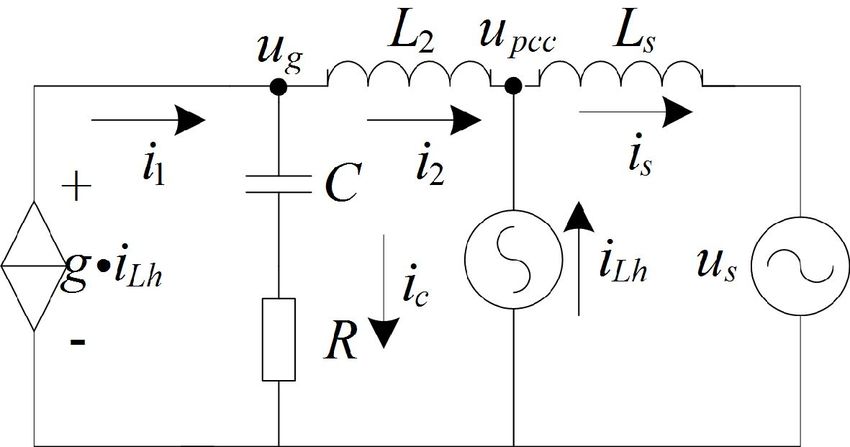
ELEKTRONIKA IR ELEKTROTECHNIKA, ISSN 1392–1215, VOL. 20, NO. 5, 2014
relationship between damping ratio, resonant frequency and damping resistor R.
attenuation degree of switching ripples, which is used for Different type of Z L can impact upon characteristics of
system’s generalized design. In Section IV, an improved LCL filter system. It is not the focus of this paper; hence,
control strategy correcting magnitude and phase for output some relevant conclusions are given here directly. When Z L
current is proposed. Simulation and experimental results are
represents a capacitive load, extra resonant peaks will be
shown in Section V to demonstrate the validity of proposed
induced; When Z L is active resistive load, system’s damping
methods. Section VI concludes this paper.
ratio can be increased and a variety of resonance is suppressed;
II. STRUCTURE AND CHARACTERISTICS OF SYSTEM In addition, the status of an inductive load is much the same as
the condition of no load.
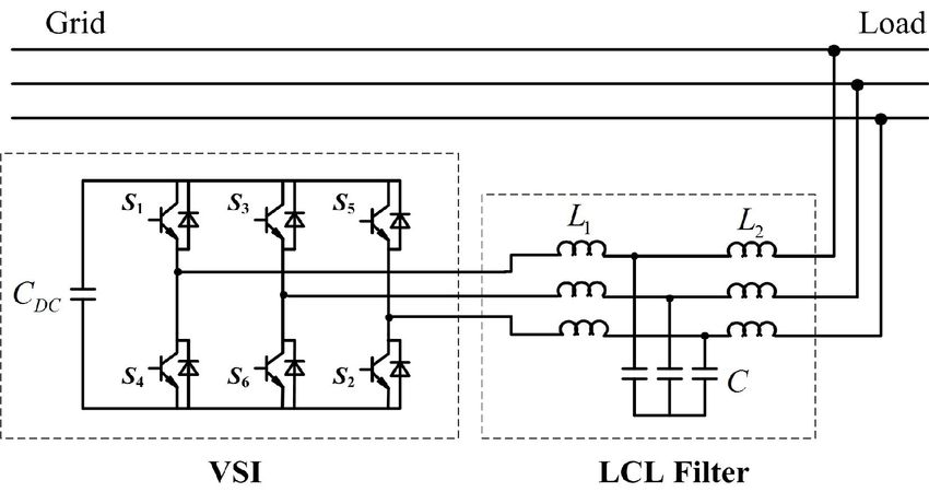
Figure 1 shows the topology of SAPF system. SAPF
Considering that the current inner loop for APF usually
consists of two basic units: one is three-phase voltage source
concentrates on the current i1 , analysis mentioned above is
inverter (VSI) with a capacitor in DC side, the other one is
LCL output filter. not applicable to the design for APF system. When system’s
sampling frequency and switching frequency are both equal
to Ts , the transfer function of current inner loop can be
approximately expressed as
i1 ( s ) 1
. (4)
i1* ( s ) 1.5Ts s 1
The precision of current inner loop tends to be high enough,
consequently, we can consider both the VSI and L1 as a
Fig. 1. Topology of SAPF system.
controlled current source. Furthermore, the improved
single-phase equivalent circuit model is as in Fig. 3.
Fig. 2. Single-phase equivalent circuit.
Figure 2 shows the model of single-phase equivalent circuit. Fig. 3. Improved single-phase equivalent circuit.
Where L1 , L2 and C comprise LCL output filter. uc is the
output voltage of three-phase VSI; us denotes the grid phase In Fig. 3, considering no-load situation, the model is
optimized and current transfer function is expressed as
voltage. Ls , R and Z L are respectively grid equivalent
inductor, damping resistor and load. The capacitor presents a i (s) sRC 1
low resistance for high frequency signal, which will shunt the G (s) 2 . (5)
i1 ( s ) s L3C sRC 1
2
switching ripple current. Unlike LC filter, which require a
large capacitance and is influenced by Ls seriously, LCL From (5), the resonant frequency of system can be obtained
filter has a larger grid–side equivalent resistance and better as
filter performance.
No-load condition ( Z L is open circuit) is the most 1
res . (6)
significant situation for analysis and design. The transfer L3C
function can be expressed by
It is denoted that the resonant frequency of system depends
i RCs 1
G(s) 2 , (1) upon total grid-side inductance L3 with no relation to L1 . As
uc L L
L1L3Cs ( s 2 R 1 3 s res
2
) a matter of fact, the resonant frequency obtained from (2) is
L1L3 recessive due to the control strategy, whereas that from (6) is
dominant and significative.
where:
III. DESIGN METHODS OF LCL FILTER
L1 L3
res , (2)
L1L3C A. Design of Total Inductance
L3 L2 Ls , (3) Total inductance means the sum of L1 and L2 . There is a
similarity between LCL filter and LC filter to design. When
From (1), there is an oscillating element in the transfer the inductance is low, RMS of current ripple will be biggish;
function. A resonant peak exists and can be weakened by whereas traceability will turn to be unsatisfactory with a high
66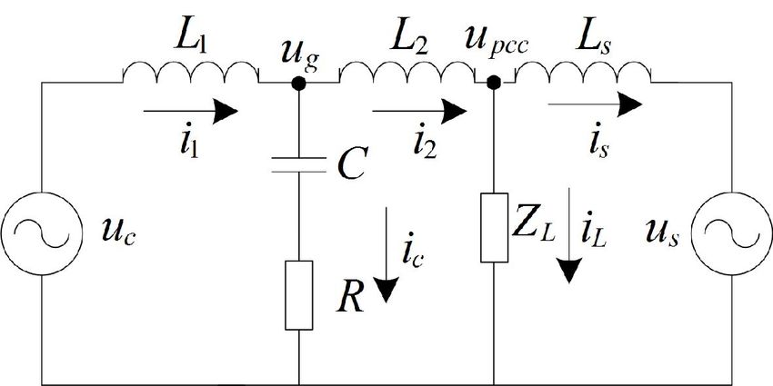
ELEKTRONIKA IR ELEKTROTECHNIKA, ISSN 1392–1215, VOL. 20, NO. 5, 2014
inductance. However, the effect of LCL filter tends to be where
much better than LC filter. Hence, the principle consideration
to design LCL filter is traceability limit. In other words, to 1
res , (11)
determine the upper limit of total inductor is crucial. L3C
For the sake of simplicity, a reduced single-phase
equivalent circuit model which ignores the influence of filter R C
. (12)
capacitor is as follows in Fig. 4. 2 L3
We can obtain the magnitude-frequency characteristic as
G ( j ) 20[lg ( RC ) 2 1
2 2
lg (1 ) 2 (2 ) ]. (13)
res
2 res
Fig. 4. Reduced single-phase equivalent circuit.
It is indicated that the oscillating element influences the
The voltage on inductor can be obtained as
2 2 2
di part lg (1 ) (2 ) . Define kres , and
u L L c uc us . (7) res
2 res
dt
the magnitude gain at the frequency of is
When U dc denotes voltage on DC bus, output voltage of 20 lg (1 k 2 )2 (2 k ) 2 dB. When res or
three-phase VSI uc has five electrical levels with 0, 1/ 3U dc res , the gain is about 0 dB. Nevertheless, when
and 2 / 3U dc respectively. Obviously, the worst situation for res the gain will trend to be infinity if 0 . When we
traceability of APF occurs at the peak of us . Without loss of introduce damping, the gain is 20 lg 2 dB and the variation
generality, assumed that us is equal to positive peak value tendency is as in Fig. 5.
2Us , where Us means the RMS value of grid phase voltage.
An average voltage of uc can be obtained as 0.5U dc
considering the coupling of three phases. Provided that A is
the maximum slope of APF output current, the formula
required is as follows
0.5U dc 2U S
A. (8)
L
Fig. 5. Magnitude with different .
Besides, regarding fundamental wave, (8) can be converted
to the following one It is indicated in Fig. 5 that magnitude is amplified when
0.5 and the larger gain the less . When 0.5 , no
2 amplification occurs for the oscillating element. In this sense,
U dc U S
2 A1 , (9) we should design larger than 0.5. However, that will
1L increase thermal losses of system by enlarging the value of R.
If a magnification below 50 % at the resonant frequency is
where A1 means the maximum RMS value of APF output required, must be larger than 0.33.
current for fundamental wave. We can convert harmonic to
fundamental wave by multiplying relative coefficient for the C. Design of Resonant Frequency
sake of simplicity. Take 100 A 5th harmonic for example, it It is important to note that there are two typical elements
can be considered as 500 A fundamental wave. Then we can with inertia differential element and oscillating element
choose the maximum corrected fundamental wave to calculate respectively. Owing to a tiny time constant, inertia differential
total inductance. element mainly performs a role in high frequency. While in
low and medium frequency, oscillating element dominantly
B. Design of Damping Ratio
affects the characteristics of system. From (10), we can obtain
Grid inductance Ls can be estimated by transformer’s the phase-frequency characteristic as
parameters. Define as the damping ratio, (5) can be
converted into the standard form as follows 2res
( j ) arctan( RC ) arctan( ). (14)
res
2
2
i RCs 1
G (s) 2 , (10)
i1 2
s s Define kres . From (13) and (14), magnitude gain and
2 1
res
2 res phase excursion are respectively
67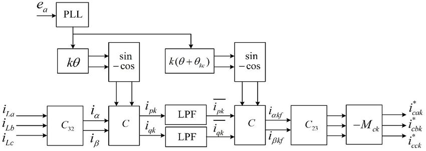
ELEKTRONIKA IR ELEKTROTECHNIKA, ISSN 1392–1215, VOL. 20, NO. 5, 2014
2 k
20 lg (1 k 2 )2 (2 k ) 2 dB and arctan( ) radian. G ( js ) 20[lg (s RC ) 2 1
1 k2
The characteristics when 0.5 or 0.33 and k 1 are lg (s RC )2 (1 s2 L3C )2 ] B, (15)
as in Fig. 6.
where s is switching frequency and B is the gain to achieve.
4 Define attenuation degree of switching ripple as and it can
0.33
be obtained from (10) as follows
2 0.5
I 2 (s ) (s RC ) 2 1
. (16)
I1 (s ) (s RC ) 2 (1 s2 L3C ) 2
0
0 0.5 1
k Define
a)
0
h res / s . (17)
0.33
30
From (11), (12), (16) and (17) simultaneously, can be
0.5
60 determined uniquely by and h as follows
90
0 0.5 1 4 2
k 1
b) h2 . (18)
Fig. 6. Characteristics when k 1. 4 2
1 2
1 2
h2 h4 h
From Fig. 6(a), it is indicated that magnitude is enlarged
when k 1 and a higher damping can restrain the gain better. A 3D graphic can be plotted as in Fig. 8.
From Fig. 6(b), it is noteworthy that phase excursion occurs
across LCL filter and a higher damping leads to a more
0.8
2
serious delay. Specifically, if res , when 0.33 0.6
3
0.4
magnitude reach about 3 dB which means current is enlarged 0.2
by 41 %, and phase delay is 38°; when 0.5 , magnitude is 0
0.6
1.23 dB which means current is enlarged by 15 %, and phase 0.5
0.4
0.3
0.4
0.5
0.3
0.2
delay is 50°.Consequently, resonant frequency must exceed h 0.2
0.1 0
0.1
APF’s compensation bandwidth by 50 % in order to reduce Fig. 8. 3D graphic on relationship of three factors.
the adverse effect from the oscillating element.
In addition, Fig. 7 shows the magnitude characteristics From Fig. 8, it is indicated that increases rapidly as we
when k 1 . It is indicated that magnitude characteristics tend enhance . When is small, is always low however
to turn superposition for different damping. If k 2 , gain is much h is. However, when is big such as 0.5, is at least
-10.3 dB and -11.14 dB with 0.33 , 0.5 respectively, 50 % when h 0.1 . As a result, we usually determine and
which means an attenuation by 70 % at least. Hence, resonant h reasonably in order to reduce the value of . In general,
frequency should be below half of switching frequency.
should be below 0.2 to ensure the switching ripple filter effect.
In some fastidious occasions, may be chosen below 0.15.
E. Global Design Methods
How to design LCL filter in APF integrally?
To begin with, we should make certain of the capacity and
application. Total inductance can be obtained from methods
indicated above. The maximum value of capacitor usually is
chosen below 5 % of APF’s capacity. Switching frequency of
Fig. 7. Characteristics when k 1.
APF can be determined by the capacity and heat-sinking
D. Attenuation Degree of Switching Ripple capability which is generally below 10 kHz for actual
The chief purpose to use LCL filter is to prevent switching applications. Target value of should be chosen according
ripple from injecting into grid. Therefore attenuation degree to actual conditions.
of switching ripple is an important indicator to design and Moreover, we can obtain resonant frequency and damping
evaluate LCL filter. ratio from methods proposed above.
From (10), magnitude at the switching frequency is Last but not least, check the value of using (18). If is
68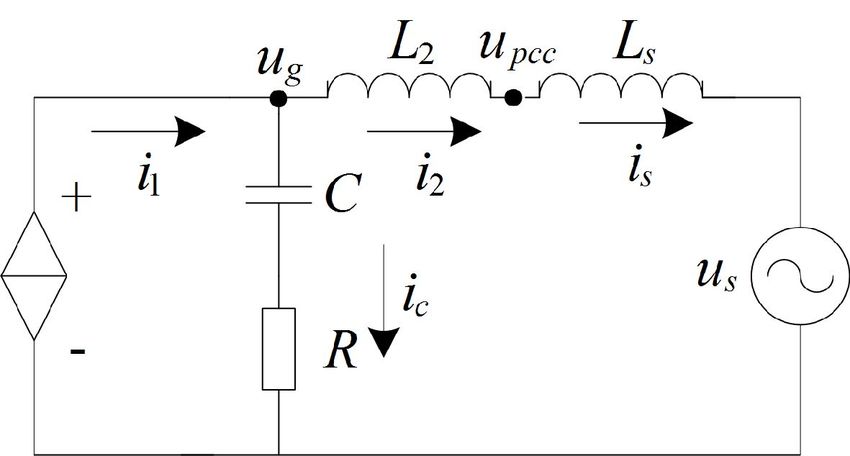
ELEKTRONIKA IR ELEKTROTECHNIKA, ISSN 1392–1215, VOL. 20, NO. 5, 2014
dissatisfactory, try reducing h or . ALL the parameters of transformation, k-order harmonic current reference can be
LCL filter are achieved. obtained by multiply -1 considered reference direction
traditionally. Here magnitude compensation is introduced,
IV. OPTIMIZATION CONTROL METHODS where M ck is a compensation factor obtained by (13).
If grid load is harmonic source, the model of single-phase Through feeding forward magnitude and phase compensation,
equivalent circuit of system is as follows as in Fig. 9. the adverse effect of LCL filter can be reduced.
V. SIMULATION AND EXPERIMENT RESULTS
Here an example to design APF with 200A capacity is
provided. Filter capacitor chooses 60 uF delta connected
which introduce reactive current of 12.4 A, and this meets the
rule that reactive current should be below 5 % of capacity
mentioned above approximately. The total inductance should
Fig. 9. Single-phase equivalent circuit. be below 0.28 mH when U dc 800V using the rule on total
In Fig. 9, iLh is harmonic current source. Because ideal inductance. Switching frequency of system is decided to be
5 kHz for the purpose of reducing switching loss. The
harmonic voltage source is inexistent, practical nonlinear load
maximum order harmonic to compensate is 13th, and resonant
can be equivalent to harmonic current source with different
frequency should be chosen between 1 kHz and 2.5 kHz
peaks. Compensation coefficient g is usually equal to -1.
according to the rule proposed above. Based on the parameter
If i2 i1 iLh , harmonic will be compensated of transformer in experiment place, an estimated value of Ls
completely. Unfortunately, i2 changes not only magnitude is 0.04 mH. We choose L2 0.07 mH and resonate
but also phase compared with i1 as indicated above. frequency is 1.13 KHz calculated by (6). From (17), it can be
Consequently, traditional feed-forward control methods obtained that h 0.226 . Damping ratio is chosen to be
which i1 is equal to iLh cannot achieve nice effect 0.32 and 0.16 can be obtained from (18). As a result, we
especially when resonate frequency is low. Factually, due to a can choose L1 0.2mH , R 0.5 (Y connection).
low switching frequency, this situation often occurs.
A model is established with Matlab Simulink according to
If used adequate magnitude and phase compensation to
parameters above. Nonlinear load adopts harmonic current
reference value of i1 , to make i2 iLh can eliminate the
source. The RMS of harmonic is shown in Table I.
adverse effect of LCL filter.
Harmonic can be extracted by synchronous rotating TABLE I. LIST OF HARMONIC.
5th 7th 11th 13th
transformation methods which can easily distinguish RMS(A) RMS(A) RMS(A) RMS(A)
THD (%)
positive-order and negative-order components from current. Load side 132 88.5 36 15 149.5 %
The schematic diagram of harmonic extraction is showed in Grid side
without 5.47 11.64 11.16 4.76 15.97 %
Fig. 10. correction
With
magnitude 5.29 9.24 6.53 4.67 12.2 %
correction
With phase
5.02 8.73 7.74 2.96 12.16 %
correction
With
magnitude
4.65 7.93 3.77 4.00 10.18 %
and phase
correction
Fig. 10. Harmonic extraction methods.
Load current is transformed by Clarke and Park matrix into Firstly, resonant frequency is 1.13 KHz according to (6),
i pk and iqk which represent active harmonic current and whereas it is 1.41 KHz obtained from (2). A contrast of the
gain is listed in Table II. It is shown that the magnification
reactive harmonic current respectively. The harmonic order
times with the (3) are much larger and validity of the proposed
k is positive value when we are to extract positive-order
method to obtain resonant frequency is proved. Meanwhile,
harmonic; k is negative value when we are to extract the gain is about 1.6, which is accordant to design method on
negative-order harmonic. is the phase angel of A-phase damping ratio mentioned above.
fundamental voltage obtained from phase-locked loop. Moreover, magnitude compensation factor M ck and the
Through Park transformation, k-order harmonic turns into DC
lead angle kc for various orders harmonic can be obtained
component which can be extracted by a Low-pass filter, and
the other order harmonics are transformed into AC from (13) and (14) which are listed in Table III.
component. Traditionally, Park inverse transformation uses
TABLE II. MAGNITUDE GAIN AROUND RESONANCE FREQUENCY.
the same phase information with direct transformation. Here a 1125Hz 1150Hz 1400Hz 1425Hz
novel control strategy is proposed, which makes a lead Peak of i1 0.3 0.78 0.51 0.94
compensation for Park inverse transformation. kc is the lead Peak of i2 0.46 1.26 0.66 1.08
angle obtained by (14). Through Clarke inverse Gain 1.53 1.61 1.29 1.15
69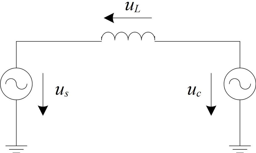
ELEKTRONIKA IR ELEKTROTECHNIKA, ISSN 1392–1215, VOL. 20, NO. 5, 2014
TABLE III. MAGNITUDE AND PHASE COMPENSATION FACTOR. and total harmonic elimination rate reaches up to 94.7 %
Order 5th 7th 11th 13th
which is very satisfactory.
M ck 1/1.0503 1/1.1013 1/1.2702 1/1.3946
To further determine the effectiveness and validity of the
kc (radian) 0.0071 0.0201 0.0853 0.1497 proposed method, an experiment is accomplished in the
laboratory. Figure 12 is the photo of the laboratory prototype.
400
As is showed, APF and thyristor switched capacitor (TSC)
compose a hybrid system to compensate the reactive power
i L (A)
0 and harmonic current generated by inductors and SCR
rectifier loads in the grid respectively. In the experiment, only
400 SCR rectifier loads are connected to the grid and the RMS
0.25 0.26 0.27 0.28 0.29
time(s) value of harmonic current in load side is showed in Table IV.
a) Then APF prototype with the compensation capacity of
200
100 KVA is switched on to verify the proposed method.
Parameters of LCL filter for APF are as follows: L1 0.3mH ,
iS (A)
0
L2 0.075mH , C =90uF , R 0.5 (Y connection).
200
Inductors and capacitors in LCL filter are available in the
0.25 0.26 0.27
time(s)
0.28 0.29 laboratory but not with the best value, which induces the
b) damping ratio to be only 0.15. The RMS value of grid line
200
voltage is 380 V, and DC-side voltage for APF is 760 V
accordingly. Switching frequency for APF is 5 KHz, and 5th,
iS (A)
0 7th, 11th, 13th harmonic current is selected to be compensated.
200
0.25 0.26 0.27 0.28 0.29
time(s)
c)
200
iS (A)
0
200
0.25 0.26 0.27 0.28 0.29
time(s)
d)
200
iS (A)
0
200 Fig. 12. Photo of Laboratory prototype.
0.25 0.26 0.27 0.28 0.29
time(s) From Fig. 13, grid current after compensation is not ideal.
e)
This is mainly because inductors and capacitors in LCL filter
Fig. 11. Current waveforms for simulation: a) Load current; b) Grid current
without correction; c) Grid current with magnitude correction; d) grid are existing but not with the best value, which induces the
current with phase correction; e) Grid current with magnitude and phase damping ratio to be only 0.15. Resonant frequency is
correction. approximately 1.5 kHz and the circumambient harmonic is
enlarged obviously. Another reason is the adoption of
From Fig. 11, it is indicated that load current has a serious
selective harmonic compensation strategy which means only
distortion. After compensation by APF, grid current becomes
5th, 7th, 11th, 13th harmonic is chosen. Nevertheless, it is
approximately sinusoidal but not ideal. There are several
indicated that after magnitude and phase correction grid
reasons influencing compensation performance. Firstly, the
current is more sinusoidal. From Table IV, after magnitude
harmonic RMS of load current is very large, which is a rather
and phase correction harmonic elimination has a better
awful occasion and difficult to compensate by APF due to a
performance for all the selected harmonics. THD of load
steep changing current. Secondly, the resonant characteristics
current reaches up to 73.2 %, and THD of grid current
of LCL filter make APF’s output current distorted. Last but
decreases from 22.2 % to 15.1 % using the strategy proposed
not least, the control strategy is imperfect and system’s
inertial and delay elements decrease the accuracy of current TABLE IV. LIST OF HARMONIC AFTER COMPENSATION.
tracking. On the other hand, from Table I, compensation 5th 7th 11th 13th
effect is obviously improved when using correction. With Load
28.2 15.9 6.1 5.6
individual magnitude or phase correction, THD of grid current(A)
Without
current reduces to 12.2 %, when we correct magnitude and correction
5.1 3.5 3.8 3.0
phase, integrated compensation effect is the best during the With
2.1 1.6 2.8 1.6
methods provided. THD of grid current reduces to 10.18 % correction
70ELEKTRONIKA IR ELEKTROTECHNIKA, ISSN 1392–1215, VOL. 20, NO. 5, 2014
conditions”, Elektronika ir Elektrotechnika, vol. 19, no. 1, pp. 35–39,
2013. [Online]. Available: http://dx.doi.org/10.5755/j01.
iL eee.19.1.3247
[5] M. Liserre, F. Blaabjerg, S. Hansen, “Design and control of
LCL-filter-based three-phase active rectifier”, IEEE Trans. Industrial
Applications, vol. 41, pp. 1281–1291, 2005. [Online]. Available:
http://dx.doi.org/10.1109/TIA.2005.853373
[6] Guo Xizheng, You Xiaojie, Li Xinran, Hao Ruixiang, Wang Dewei,
iS “Design method for the LCL filters of three-phase voltage source PWM
rectifiers”, Journal of power electronics, vol. 12, pp. 559–566, 2012.
[7] J. Dannehl, C. Wessels, F. W. Fuchs, “Limitations of voltage-oriented
PI current control of grid-connected PWM rectifiers with LCL filters”,
time(10ms/div)
IEEE Trans. Industrial Electronics, vol. 59, pp. 380–388, 2009.
a) [Online]. Available: http://dx.doi.org/10.1109/TIE.2008.2008774
[8] Zhixiang Zou, Zheng Wang, Ming Cheng, “Modeling, analysis, and
design of multifunction grid-interfaced inverters with output LCL
iL filter”, IEEE Trans. Power Electronics, vol. 29, pp. 3830–3839, 2014.
[Online]. Available: http://dx.doi.org/10.1109/TPEL.2013.2280724
[9] K. Jalili, S. Bernet, “Design of LCL filters of active-front-end two-level
voltage-source converters”, in IEEE Trans. Industrial Electronics,
vol. 56, pp. 1674–1689, 2009. [Online]. Available:
http://dx.doi.org/10.1109/TIE.2008.2011251
iS [10] Weimin Wu, Yuanbin He, Tianhao Tang, F. Blaabjerg, “A new design
method for the passive damped LCL and LLCL filter-based
single-phase grid-tied inverter”, IEEE Trans. Industrial Electronics,
vol. 60, pp. 4339–4350, 2013. [Online]. Available:
http://dx.doi.org/10.1109/TIE.2012.2217725
time(10ms/div)
[11] I. J. Gabe, V. F. Montagner, H. Pinheiro, “Design and implementation
b) of a robust current controller for VSI connected to the grid through an
Fig. 13. Current waveforms for experiment: a) Current without correction; b) LCL filter”, IEEE Trans. Power Electronics, vol. 24, pp. 1444–1452,
Current with correction. 2009. [Online]. Available: http://dx.doi.org/10.1109/
TPEL.2009.2016097
VI. CONCLUSIONS [12] Huichun Huang, Renjie Hu, Guiping Yi, “Research on dual-loop
controlled grid-connected inverters on the basis of LCL output filters”,
This paper has made the following conclusions on the basis Elektronika ir Elektrotechnika, vol. 20, no. 1, pp. 8–14, 2014. [Online].
of previous studies: Available: http://dx.doi.org/10.5755/j01.eee.20.1.5589
[13] M. Pastor, J. Dudrik, “Design of output LCL filter for 15-level cascade
A single-phase equivalent circuit model has been inverter”, Elektronika ir Elektrotechnika, vol. 19, no. 8, pp. 45–48,
established to analyse the characteristics of LCL filter applied 2013. [Online]. Available: http://dx.doi.org/10.5755/j01.eee.
in APF. Oscillating element leads to a resonance peak 19.8.5394
[14] J. Muhlethaler, M. Schweizer, R. Blattmann, J. W. Kolar, et al.,
enlarging harmonic. Resonant frequency depends upon total “Optimal design of LCL harmonic filters for three-phase PFC
grid-side inductor with no relation to inverter-side inductor rectifiers”, IEEE Trans. Power Electronics, vol. 28, pp. 3114–3125,
owing to the function of inverter current loop. 2013. [Online]. Available: http://dx.doi.org/10.1109/T
PEL.2012.2225641
We proposed a set of methods to design LCL filter. Total
[15] Wang Yaoqiang, Wu Fengjiang, Sun Li, Sun Kui, “Optimized design
inductance is restricted by the capability of APF. Damping of LCL filter for minimal damping power loss”, Proc. CSEE, vol. 27,
ratio, attenuation degree of switching ripples and resonant pp. 90–95, 2010.
frequency are the crucial factors to determine the performance [16] Tang Yi, Poh Chiang Loh, Wang Peng, Fook Hoong Choo, Gao Feng,
F. Blaabjerg, “Generalized design of high performance shunt active
of LCL filter. Intrinsic relation of them has been presented power filter with output LCL filter”, IEEE Trans. Industrial
and a comprehensive consideration is essential. Electronics, vol. 3, pp. 1443–1452, 2012.
LCL filter has an adverse effect on magnitude and phase of [17] Xiaohu Zhou, Jiwei Fan, A. Q. Huang, “High-frequency resonance
mitigation for plug-in hybrid electric vehicles’ integration with a wide
compensation current. A correction method using range of grid conditions”, IEEE Trans. Power Electronics, vol. 27, pp.
synchronous rotating transformation has been proposed and 4459–4471, 2012. [Online]. Available: http://dx.doi.org/10.1109/T
demonstrated by simulation and experimental results. Further PEL.2012.2185833
[18] Yunwei Li, “Control and resonance damping of voltage-source and
studies may be needed on adapting to varying parameters of
current-source converters with LC filters”, IEEE Trans. Industrial
system. Electronics, vol. 56, pp. 1511–1521, 2009. [Online]. Available:
http://dx.doi.org/10.1109/TIE.2008.2009562
[19] J. Dannehl, M. Liserre, F. W. Fuchs, “Filter-based active damping of
REFERENCES voltage source converters with LCL filter”, IEEE Trans. Industrial
[1] H. Akagi, E. H. Watanabe, M. Aredes, Instantaneous power theory Electronics, vol. 8, pp. 3623–3633, 2011. [Online]. Available:
and applications to power conditioning. New Jersey, USA: John Wiley http://dx.doi.org/10.1109/TIE.2010.2081952
& Sons; 2007. [Online]. Available: http://dx.doi.org/10.1002/ [20] M. Hanif, V. Khadkikar, Weidong Xiao, J. L. Kirtley, “Two degrees of
0470118938 freedom active damping technique for LCL filter-based grid connected
[2] M. Angulo, D. A. Ruiz-Caballero, J. Lago, M. L. Heldwein, et al., PV systems”, IEEE Trans. Industrial Electronics, vol. 61,
“Active power filter control strategy with implicit closed-loop current pp. 2795–2803, 2014. [Online]. Available: http://dx.doi.org/10.1109/
control and resonant controller”, IEEE Trans. Industrial Electronics, TIE.2013.2274416
vol. 60, pp. 2721–2730, 2013. [Online]. Available: [21] M. Liserre, A. Dell'Aquila, F. Blaabjerg, “Genetic algorithm-based
http://dx.doi.org/10.1109/TIE.2012.2196898 design of the active damping for an LCL-filter three- phase active
[3] Xinyang Liu, Jie Wang, Gang Yao, “A novel hysteresis current control rectifier”, IEEE Trans. Power Electronics, vol. 1, pp. 76–86, 2004.
strategy with fuzzy bandwidth for active power filter”, Elektronika ir [Online]. Available: http://dx.doi.org/10.1109/TPEL.2003.820540
Elektrotechnika, no. 4, pp. 3–8, 2012. [Online]. Available: [22] N. Mukherjee, D. De, “Analysis and improvement of performance in
http://dx.doi.org/10.5755/j01.eee.120.4.1442 LCL filter-based PWM rectifier/inverter application using hybrid
[4] S. Biricik, O. C. Ozerdem, S. Redif, “Performance improvement of damping approach”, IET Power Electronics, vol. 6, pp. 309–325, 2013.
active power filter under distorted and unbalanced grid voltage [Online]. Available: http://dx.doi.org/10.1049/iet-pel.2012.0032
71You can also read