48 Joule High Energy Spark Igniter (HESI) - User Manual Publication 372001-16 Rev. B - Forney Corporation
←
→
Page content transcription
If your browser does not render page correctly, please read the page content below

48 Joule High Energy Spark Igniter (HESI)
User Manual
Publication 372001-16 Rev. B
48 Joule HESI Igniter User Manual
372001-16 Rev. B

INTRODUCTION
This manual contains information for the 48 Joule High Energy Spark Igniter (HESI) from
Forney Corporation, 16479 Dallas Parkway, Suite 600, Addison, Texas. www.forneycorp.com

All personnel should become thoroughly familiar with the contents of this manual before
attempting to use the Forney 48 Joule High Energy Spark Igniter (HESI). Because it is virtually
impossible to cover every situation that might occur during operation and maintenance of the
equipment described in this publication, personnel are expected to use good engineering
judgment when confronted with situations that are not specifically mentioned herein.

PROPRIETARY NOTICE
The contents of this publication are proprietary data of Forney Corporation. Forney reserves all
proprietary rights to this document, including all design, manufacturing, reproduction, use, and
sales rights thereto, except to the extent said rights are expressly granted to others.

SAFETY ICON DEFINITIONS

                                     Indicates a hazardous situation which, if not avoided, will result in
           DANGER                                        death or serious injury.

        WARNING                      Indicates a hazardous situation which, if not avoided, could result
                                                        in death or serious injury.

           CAUTION                   Indicates a hazardous situation which, if not avoided, could result
                                                       in minor or moderate injury.

           NOTICE                    Indicates unsafe practices that can result in property damage only.

Revision       Date                 Comments
    A          01/24/2017           Initial Release
    B          02/19/2018           Update spark tip temperatures and safety icons

 This is an agency controlled document. FM must be notified if this document changes. Do not
 change this document without prior consent from the Manager of Agency Certifications.

                                                  i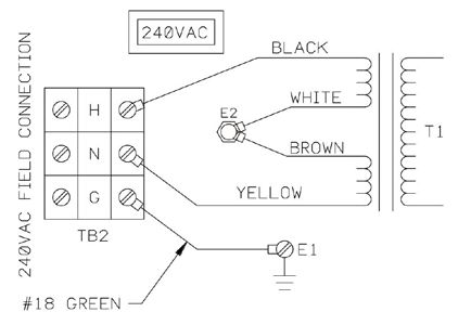
48 Joule HESI Igniter User Manual
372001-16 Rev. B

                                                             Table of Contents

Section 1 Description.................................................................................................... 3
   1.1     Features and Benefits ...................................................................................................................... 3

Section 2 Specifications ............................................................................................... 4

Section 3 Safety ............................................................................................................ 5

Section 4 Installation .................................................................................................... 6
   4.1     Overview of Installation .................................................................................................................... 6
   4.2     Power pack ...................................................................................................................................... 6
   4.3     Spark Rod ........................................................................................................................................ 7
   4.4     Cable Assembly ............................................................................................................................... 9

Section 5 Commissioning ............................................................................................ 9

Section 6 Operation .................................................................................................... 10
   6.1     Troubleshooting ............................................................................................................................. 10

Section 7 Maintenance................................................................................................ 11
   7.1     Spark Tip Inspection and Maintenance.......................................................................................... 11
   7.2     Power Pack Inspection and Maintenance ...................................................................................... 11
   7.3     Spark Gap Tube Operation Verification ......................................................................................... 11
   7.4     Cable Inspection and Maintenance ................................................................................................ 11

Section 8 Storage ........................................................................................................ 11

Section 9 RMA / Warranty........................................................................................... 12

Section 10 Spare Parts ............................................................................................... 12
   10.1 Recommended Spare Parts ........................................................................................................... 12

                                                              Table of Figures

Figure 1 HESI Components .......................................................................................................................... 3
Figure 2 HESI Power Pack ........................................................................................................................... 6
Figure 3 HESI Spark Rod ............................................................................................................................. 7
Figure 4 HESI Mount Tube with Quick Disconnect Packing Gland ............................................................ 8
Figure 5 HESI with Retraction Assembly..................................................................................................... 8
Figure 6 Electrical Connections for Cable Assembly ................................................................................... 9

                                                                             ii
48 Joule HESI Igniter User Manual
372001-16 Rev. B
Section 1 Description
The High Energy Spark Igniter (HESI) is a Class 3 igniter used for direct spark ignition of oil or gas
igniters or small burners. The 48 Joule of power delivered to the spark tip easily ignites the fuel.
Approximately five (5) sparks per second are delivered. The High Energy Spark Igniter consists of three
major components: a power pack, a spark rod, and a cable. Optional retraction units are available.
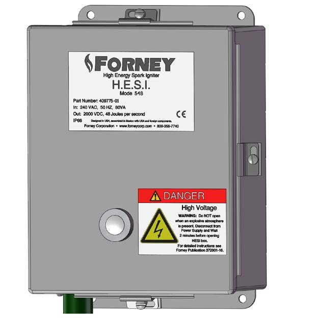
The 48 Joule HESI power pack is packaged in a NEMA-4 enclosure suitable for wall mounting at the
burner front. The power pack sends 48 joules of energy to the spark tip through heavy-duty electrical
components. It has a 15-minute on and 30-minute off maximum fire cycle at temperatures up to 140°F
(60°C). The proof of spark feature provides local indication that the power unit is functioning properly.
The spark rod is available in the standard rigid design or in a flexible configuration for use in tilting
tangential burner applications. The spark rod features a self-cleaning surface gap spark tip that is easily
replaceable through a threaded connection. Both the rigid and flexible spark rods are available with an
optional retraction assembly to allow the spark tip to be inserted and retracted from the firing position.
1.1 Features and Benefits
• Non-fouling Spark Tip - The surface gap spark tip produces a self-cleaning, highly reliable, 48
Joule per second even in the presence of moisture, oil, and carbon deposits.
• Removable Spark Tip - The spark tip completely detaches from the spark rod through a
threaded connection making replacement of the spark tip quick and easy.
• Safe Operation - Heavy-duty, UL-approved flexible cable connects the power unit to the spark
rod assembly ensuring operator safety.
• Application Flexibility - Standard, flexible and retractable HESI models are available to fit a
variety of igniter or burner types.
• Proof of Spark Indication - Both a visual and a contact output is available for proof of spark
indication.
Figure 1 HESI Components
348 Joule HESI Igniter User Manual
372001-16 Rev. B
Section 2 Specifications
Igniter Class: Class 3 Special
Approval: Factory Mutual
Output Energy: 48 Joule per second
Output Voltage: 2000 VDC
Input Voltage: 240 VAC, 50 Hz
Input Power: 240 VAC @ 0.75A (1-A fuse)
Spark Rate: 5 sparks per second
Spark Rod Length: 195 in. (495.3 cm) maximum
Spark Rod Diameter: 0.625 in. (1.6 cm)
Spark Tip Type: Gas tight, surface gap
Spark Tip Length: 6, 8 and 27 inches (15.24 cm, 20.32 cm and 68.58 cm)
Spark Tip Material: High temperature alloy with a silicon carbide insulator
1112°F (600° C);
Operating Tip Temperature:
Higher temperature during duration of light-off
Power Unit Temperature Ratings: -40°C to 60°C ( -40°F to 140°F )
Power Pack Enclosure (NEMA-4, 4X):
Dimensions: 10” x 8” x 4.25” (25.4 cm x 20.32 cm x 10.8 cm)
Weight: 17 lbs
Field Conduit Hole Diameter 0.88 in. (2.2 cm)
Power Cable: 12 gage, 3000 v in 0.5” (1.27 cm) flexible conduit
Power Cable Lengths: 6, 12, 15 ft (1.8, 3.65, 4.57 m)
15 minutes on and 30 minutes off (maximum ambient
Maximum Firing Cycle:
temperature of 60°C (140°F)
448 Joule HESI Igniter User Manual
372001-16 Rev. B
Section 3 Safety
Safety is the responsibility of each individual who installs, operates, or maintains Forney equipment. The
Forney design of the HESI includes personnel safety as a basic design element.
WARNING
Hazardous voltage is present and serious injury to personnel can occur.
WARNING
Explosion Hazard.
Do not connect or disconnect while the circuit is live or unless the area is free of ignitable
concentrations.
The HESI assembly uses a 2000-vdc energy source to produce 48 joules per second for fuel ignition
purposes. Observe the following safety instructions as a minimum to ensure basic electrical safety.
1. Use equipment only for its intended use.
2. Follow the proper installation, operation, and maintenance procedures discussed in this
publication.
3. Ensure that all electrical apparatus used to perform work on this equipment is in good
working order and calibrated correctly.
4. Do not lift or disconnect grounding cables/wires while equipment is energized.
5. Do not perform modifications on this equipment.
6. Before opening the power pack’s hinged cover, disconnect the electrical supply from the box.
Allow at least 2 minutes for the capacitor to discharge. Exercise extreme care when the power
pack cover is open.
7. Before disconnecting terminals, place a voltmeter across terminals 1 and 2 of capacitor Cl to
ensure that no voltage is present.
8. Adhere to safety-related information on all drawings.
9. Before applying the energizing signal to the assembly, fully connect the spark rod to the
power unit.
10. When the HESI spark rod is removed from its operating position for testing, do not attempt to
energize it without taking precautions. Lay the spark rod in a secure position. Ensure that
personnel are not in contact with the spark rod during the test period. Replace the rod
immediately following testing.
WARNING
Only knowledgeable and qualified technicians should be allowed access to this system or to
its components. The installation, maintenance, and operation of electronic equipment
entails several elements of danger. Carelessness can result in serious injury or death from
electrical shock, falls, or improper use of tools and test equipment.
548 Joule HESI Igniter User Manual
372001-16 Rev. B
Section 4 Installation
4.1 Overview of Installation
(For Quick Start Up)
1. Mount the power pack in a suitable location, as far as possible from the burner front plate and
extreme temperatures. Ensure that cable connectors are facing downward.
2. Carefully insert the HESI spark rod tip into the guide tube until the spark rod extends into the
primary ignition zone. If using the HESI in combination with gas or oil igniters, refer to your
igniter manual for spark tip location.
3. If retraction assembly is supplied, manually or automatically exercise the retract assembly to
verify correct operation.
4. Once tip penetration is set, attach and tighten the locking device to the spark rod.
5. Connect cable assembly from the power unit to the spark rod. Tighten threaded connection.
6. Connect power input leads to H (hot), N (neutral), and G (ground) to terminal block 2 inside the
power pack.
7. Energize the power pack to test the spark tip. Observe proper operation.
4.2 Power pack
Observe the following steps for installing the power pack assembly:
1. Locate power pack away from extreme temperatures and as far away from burner front plate as
possible. Allow for cable length, retraction, and boiler expansion.
2. Mount the power pack with fasteners through the four mounting holes. Ensure that the cable
connectors are facing down (power pack is upright) to facilitate cable installation.
Figure 2 HESI Power Pack
648 Joule HESI Igniter User Manual
372001-16 Rev. B
4.3 Spark Rod
In most applications, the HESI spark rod fits into a guide tube of a gas or oil igniter. If using the HESI in
combination with gas or oil igniters (i.e. Forney’s MaxFire® or DuraFire®), refer to your igniter manual
for additional information. Observe the following steps for installing the spark rod assembly into a gas or
oil igniter:
1. Carefully insert the spark tip into the guide tube until the spark rod extends into the primary ignition
zone. If using the HESI in combination with gas or oil igniters, refer to your igniter manual for spark
tip location.
2. When a retraction assembly is supplied, exercise the retract cylinder, either manually or
automatically, in the extend and retract positions to check for correct operation.
3. Once the tip penetration is set, attach and tighten the locking device to the spark rod.
Figure 3 HESI Spark Rod
In applications where the HESI spark rod is installed individually, the HESI mount tube is fixed
permanently to the burner front plate and supports the HESI assembly. The design of the HESI allows the
user to weld the HESI mount tube directly to the burner front plate, if desired.
1. Cut a hole through the burner front plate in the location desired or as indicated on the installation
drawing. The diameter of the hole should be slightly larger than the outside diameter of the HESI
mount tube which is 1.05”.
2. Insert the mount tube through the front plate and into the burner area. Support the mount tube at
the position and penetration angle required by the burner manufacturer.
3. Seal-weld the HESI mount tube to the burner front plate. On some older installations where cast
iron plates must be penetrated, a steel flange or cover plate can be bolted to the cast iron, so that
the HESI mount tube can be welded to that flange or plate. When installing the HESI mount tube,
avoid contact with internal burner parts, such as air vanes or burner sleeves. Occasionally, air
vanes may have to be trimmed in order to provide clearance for the HESI mount tube.
4. Before inserting the HESI into the HESI mount tube, inspect the primary combustion region for
cleanliness.
5. Insert the HESI into the HESI mount tube and tighten the packing gland once the HESI is inserted
to the correct depth.
6. If applicable, install the HESI retraction assembly onto the HESI mount tube using the HESI
retraction assembly mounting clamp and then connect HESI to HESI retraction assembly using
748 Joule HESI Igniter User Manual
372001-16 Rev. B
the provided couplings.
7. Once the HESI retraction assembly is installed, adjust the retraction settings, and wire the limit
switch.
Figure 4 HESI Mount Tube with Quick Disconnect Packing Gland
Figure 5 HESI with Retraction Assembly
848 Joule HESI Igniter User Manual
372001-16 Rev. B
4.4 Cable Assembly
Connect power input leads to TB2, H (hot), N (neutral), and G (ground) to the power pack as shown in
installation drawings and in Figure 2.
Figure 6 Electrical Connections for Cable Assembly
Section 5 Commissioning
When you have completed the installation, perform a spark test and observe spark rod operation in the
following manner.
1. Energize the power pack and observe the operation of the spark gap tube.
2. The spark rod assembly is functioning properly when discharge of approximately three sparks per
second is visible.
If the spark rod cannot be observed in place,
a. De-energize the power pack and mark the rod so it can be repositioned to its previous
location.
b. Remove the rod and place it in a safe location away from any personal contact.
c. Energize the power pack and observe the rod for visible emission of three sparks per
second.
d. If the spark rod assembly functions properly, de-energize the power pack and reinsert the
rod into the guide tube at the rod’s original position.
3. If the rod functions properly, energize the system to observe the rod’s performance with its
associated fuel gun.
Check the following items:
a. Igniter fuel pressure,
b. Atomizing media pressure, and
c. Combustion air pressure.
(Refer to the appropriate igniter service manual for pressure specifications.)
The HESI rod may need repositioning if the HESI system functions properly but the igniter does
not light.
4. To test other HESI locations, start from the current location and move the HESI rod inward 0.5
inch (13 mm) and retest. Continue to move the HESI rod inward and outward 0.5 inch (13 mm)
at a time, testing after each move. Do not move the rod more than 3 inches (76mm) in any
direction.
948 Joule HESI Igniter User Manual
372001-16 Rev. B
Section 6 Operation
The HESI igniter is a Class 3 ignition source and is only in service during an ignition time trial duration.
The HESI can operate during ignition and during oil gun shutdown and purge. Depending on the
application, the spark rod can be set in a fixed position or attached to a retraction assembly to move it out
of firing position. The spark rod should be fitted with the retraction assembly whenever the HESI spark
rod tip will be exposed to continuous temperatures above 149° C (300° F).
The burner management system provides the control signal that energizes the HESI during the ignition
time trial period. The power unit transforms the signal into short 12-joule discharges at the rate of three
sparks per second. The cable assembly transmits these discharges to the spark rod assembly.
6.1 Troubleshooting
If the HESI assembly malfunctions, ensure that the procedures described in the Commissioning section
have been performed successfully.
If problems continue to occur, refer to Table 1 for troubleshooting information.
Table 1 Troubleshooting
Symptom Probable Cause Remedy
Proof of spark visual 1. Input voltage low 1. Provide correct supply voltage.
indication not flashing 2. Power pack failure 2. Replace power pack
Proof of spark visual 1. Spark tip fouled and 1. Replace tip assembly and adjust tip to gun
indication flash weak or shorting setting as specified in drawing or igniter
erratic manual.
2. Tip insulator cracked or 2. Replace tip assembly and adjust tip to gun
damaged setting as specified in drawing or igniter
manual.
3. High-tension cable inside 3. Replace cable assembly on older models
rod broken or insulation which have cable and tip as a single
damaged subassembly. The tip must be replaced
along with the cable. Adjust tip to gun
settings specified on drawing or in igniter
manual.
WARNING
Hazardous voltage is present and serious injury to personnel can occur.
Before opening the power pack’s hinged cover, disconnect the electrical supply from the
box. Allow at least 2 minutes for the capacitor to discharge. Exercise extreme care when
the power pack cover is open.
1048 Joule HESI Igniter User Manual
372001-16 Rev. B
Section 7 Maintenance
Forney recommends performing the following preventive maintenance every six months.
7.1 Spark Tip Inspection and Maintenance
Remove the spark rod and inspect the spark tip for damage due to overheating, excessive use, and
mishandling of equipment. A concave shape of the spark tip end represents normal wear. If the
semiconductor material is chipped, cracked, or eroded, replace the spark tip. If the inner electrode, tip
center, or tube shows deterioration, wear, or erosion, also replace the spark tip. When replacing the spark
tip, observe the following steps:
1. Disconnect all electric power from the power unit, and ensure that all residual voltage is
dissipated. (See Safety section.)
2. Remove and replace tip using ½-inch wrench flats.
Note: On older models, which have cable and tip as a single subassembly, follow these steps:
a. Open the cover plate at the end of the spark rod
b. Remove the wire nut in the electrical connection and separate the wire.
c. Straighten the wire.
d. Unscrew the spark tip using the wrench flats.
e. Remove spark tip and wire.
f. Replace above items in the reverse order. Take care to minimize twisting of the wire
inside the tip during tip reconnection.
7.2 Power Pack Inspection and Maintenance
The power pack generally does not need periodic maintenance other than cleaning the exterior and
checking the hinged cover for proper closure and sealing.
If the power pack malfunctions, the following steps describe power pack inspection and maintenance.
1. Disconnect all electric power from the power pack, and ensure that all residual voltage is
dissipated. (See Safety section.)
2. Open the power pack door.
3. Test capacitor C1 for resistance across terminals 1 and 2.
4. Test transformer T1 for resistance at the two red secondary leads.
An open circuit reading on capacitor C1 and/or a low resistance value reading at transformer T1 indicates
a normal condition. If a normal condition is present, circuitry problems could exist elsewhere. Replace the
power pack.
7.3 Spark Gap Tube Operation Verification
A lens in the power pack cover allows for a visual check of the discharging operation of the spark gap
tube. A visible flashing of the spark gap tube indicates the presence of electric-discharge voltage and
delivery to the spark tip.
7.4 Cable Inspection and Maintenance
Inspect the cable for fraying or lose connections. Replace frayed cable.
Section 8 Storage
Store the HESI in a clean, dry environment. When possible, store the igniter in its original shipping
container until it is installed.
1148 Joule HESI Igniter User Manual
372001-16 Rev. B
Section 9 RMA / Warranty
Forney Corporation warrants this product to be free of defective material and workmanship. Forney will
replace this equipment as long as it is being used for its intended use and is found to be defective upon
receipt up to the expiration of the warranty period.
Prior to returning any material to Forney, please contact your Forney customer service representative and
provide the contract number or the customer purchase order number.
Section 10 Spare Parts
When ordering spare parts, contact Forney’s Aftermarket Department via any one of the following methods
and furnish the following information.
E-mail Phone Fax
spares@forneycorp.com 972-458-6100 or 972-458-6600
972-458-6142 or
1-800-356-7740 (24-hour direct line)
1. Contract number
2. Customer purchase order number
3. For each part ordered, provide the following information:
a. Part number
b. Part description
c. Quantity required
10.1 Recommended Spare Parts
The recommended spare parts list in Table 1 advises of the minimum stock level of replacement parts that
should be in the customer’s stock for system startup and the first year of operation. Replacement parts
should be ordered as necessary to maintain the suggested stock of spare parts at the recommended level.
Table 2 Recommended Spare Parts List
Part Description Part Number Quantity
Spark Tip, Short (for flexible assemblies only) 383726-01 1 for every 4 igniters
Spark Tip, Short (Spark Rods 36” and shorter) 383726-02 1 for every 4 igniters
Spark Tip, Long (Spark Rods greater than 36”) 383726-03 1 for every 4 igniters
Solenoid & Coil for Retract Assembly, 230 VAC 78892-10 1 for every 5 igniters
Coil Only for Retract Assembly, 230 VAC 78059-05 1 for every 5 igniters
Spark Gap Tube 77741-01 1 for every 5 igniters
Capacitor for 60Hz units 79942-01 1 for every 5 igniters
Capacitor for 50Hz units 79942-04 1 for every 5 igniters
Transformer 79941-00 1 for every 5 igniters
HESI Transformer, CE 79941-10 1 for every 5 igniters
1248 Joule HESI Igniter User Manual
372001-16 Rev. B
HESI Commissioning Checklist
After reading this service manual and following its instructions, complete this Commissioning Checklist
while following the guidelines discussed in the Installation and Commissioning sections. Return the
completed form to Forney Corporation.
Customer Name: ______________________________________________________________________
Contact: _____________________________________________________________________________
Plant Location: ________________________________________________________________________
Plant Unit Number: ____________________________________________________________________
Type of igniter with which HESI is used: ___________________________________________________
Check the following boxes if the listed conditions have been completed satisfactorily. Use this service
manual’s installation and commissioning guidelines while completing this checklist.
HESI spark tip location is set according to service manual and applicable drawings.
Tip location: ____________________________________________________________
Spark gap tube is operating correctly according to guidelines given in this manual (5 flashes per
second; no weak or erratic flashing, etc.)
Spark rod/tip is operating correctly according to guidelines in this service manual (5 sparks per
second)
HESI advance and retraction (if provided) functions are operating properly.
Send this form to:
Forney Corporation
Attn: Service Department
16479 Dallas Pkwy, Suite 600
Addison, TX 75001
13You can also read