EK-BG1-TP User manual - KNX - Dali Gateway - Ekinex
←
→
Page content transcription
If your browser does not render page correctly, please read the page content below
KNX - Dali Gateway
   EK-BG1-TP
  User manual
User manual
                                                                                                                   KNX-DALI Gateway EK-BG1-TP

Summary
1 Product description ........................................................................................................................................ 3
   1.1     Main features ......................................................................................................................................... 3
   1.2     Technical data ........................................................................................................................................ 3
   1.3     Scope of supply ..................................................................................................................................... 4
   1.4     System requirements for the configuration software ............................................................................. 4
   1.5     Certification and markings ..................................................................................................................... 4
2 Switching, display and connection elements ................................................................................................. 5
3 Configuration and commissioning ................................................................................................................. 6
4 Using the configuration software ................................................................................................................... 6
   4.1     Dashboard ............................................................................................................................................. 7
   4.2     Installation .............................................................................................................................................. 8
   4.3     Broadcast ............................................................................................................................................... 9
       4.3.1       Lamp parameters .........................................................................................................................10
   4.4     Groups ................................................................................................................................................. 11
       4.4.1       Group Colour Details panel ..........................................................................................................13
   4.5     Scenes .................................................................................................................................................14
   4.6     Lights....................................................................................................................................................14
       4.6.1       Parameters ...................................................................................................................................17
       4.6.2       Groups ..........................................................................................................................................17
       4.6.3       Scenes .........................................................................................................................................18
       4.6.4       Lamp colour details ......................................................................................................................18
   4.7     Information ...........................................................................................................................................19
5 ETS application: Parameters .......................................................................................................................20
   5.1     Application program structure ..............................................................................................................20
   5.2     Tab: Info on EK-BG1-TP ......................................................................................................................20
   5.3     Tab: General ........................................................................................................................................20
       5.3.1       Tab: General - Behaviour and alarms ..........................................................................................20
       5.3.2       Tab: General - IP settings .............................................................................................................21
   5.4     Tab: Groups .........................................................................................................................................22
   5.5     Tab: ECG .............................................................................................................................................22
6 ETS Application: Communication objects ....................................................................................................22
   6.1     Communication objects - General .......................................................................................................22
   6.2     Communication objects - IP settings ...................................................................................................22
   6.3     Communication objects - DALI groups ................................................................................................23
   6.4     Communication objects - DALI unit .....................................................................................................23
   6.5     Communication objects - DALI Scenes ...............................................................................................24
   6.6     Communication objects - DALI Broadcast ...........................................................................................25
7 Warnings ......................................................................................................................................................26
8 Other information .........................................................................................................................................26

Rev. 1.3 - 01/04/2021
© EKINEX S.p.A. - All rights reserved                                                                                                                          Pag. 2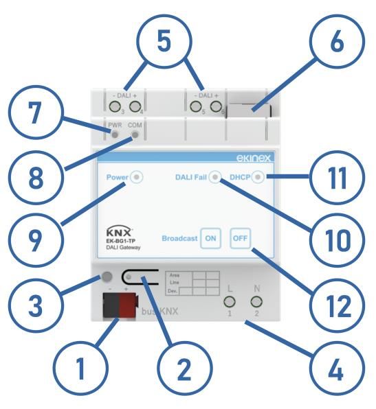
User manual
KNX-DALI Gateway EK-BG1-TP
1 Product description
The ekinex® EK-BG1-TP gateway is a modular KNX device for panel mounting, which allows you to exchange
information between a KNX system and a series of devices on the DALI bus.
The device manages a bidirectional data flow: the DALI registers are read cyclically and their value is sent on
the KNX network. The updating of the data on the KNX network can occur cyclically and / or upon variation of
the data acquired by the DALI network.
Similarly, the gateway can make requests for cyclic reading of KNX communication objects or acquire their
value during the exchange of telegrams on the bus. Either cyclically or upon variation of the communication
objects, the data are written on the DALI registers of the connected devices.
The configuration is carried out both through the ETS program (for the parametrization of the KNX bus) and
through a specific application software for PC, which communicates through the Ethernet communication port
integrated in the device. Both the ETS application and the PC application software are available for download
on the website www.ekinex.com. Use ETS v.5.6.x or newer only.
1.1 Main features
The main features of the Ekinex DALI gateway are:
Control of up to 64 DALI devices with a maximum of 16 groups and 16 scenes
Broadcast function
Individual, group or centralized addressing
Suitable for operation with different light sources (such as fluorescent lamps, high intensity discharge
lamps and LEDs)
Creation of light scenarios
Possibility of reading the status of the DALI device via KNX (for example brightness or device error)
Power supply for DALI bus incorporated
Configurator application for programming
1.2 Technical data
Feature Value
Power supply 230 V AC
Use in dry indoor environments
Operating temperature: - 40 ... + 85 ° C
Environmental conditions Storage temperature: - 25 ... + 55 ° C
Transport temperature: - 25 ... + 70 ° C
Relative humidity: 93% non condensing
Power supply LED
Display elements DALI Failure LED
DHCP ON LED
Membrane button Broadcast ON
Operation elements
Membrane button Broadcast OFF
Safety class II
Installation On DIN 35 mm profile rail (according to EN 60529)
Degree of protection IP20
Dimensions 4 modules
Ethernet interface (IEEE 802.3)
Connector RJ45 connector, cable category at least 5E
KNX TP interface
Communication port KNX TP (twisted pair), 9600 baud, galvanically isolated from the device power supply
Current draw from the KNX bus < 13 mA
DALI interface
DALI communication port Screw terminals (dual pass-through connection);
Rev. 1.3 - 01/04/2021
© EKINEX S.p.A. - All rights reserved Pag. 3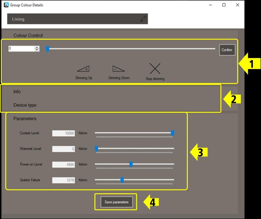
User manual
KNX-DALI Gateway EK-BG1-TP
Feature Value
galvanically isolated from the device power supply and from the KNX communication port
Baud rate 1200 bps
DALI voltage 9.5 V – 22.5 V (Nominale 14 V)
Lunghezza max cavo 300 m (Cavo 1.5 mm2)
Numero max device DALI 64
Numero max gruppi DALI 16
Numero max scene DALI 16
1.3 Scope of supply
The supply includes the device and the terminal for connection to the KNX bus. The packaging also contains
the instruction sheet of the device.
1.4 System requirements for the configuration software
Configuration and commissioning must be carried out using the CGEKBN1TP application program, available
for download on the website www.ekinex.com .
The resources required for the PC on which the application software is installed are listed below:
Desktop or laptop PC with Ethernet port
32/64 bit Operating System, Microsoft Windows® 7 or higher
i Installation of the .NET Framework 4.5 system libraries on the PC is required.
1.5 Certification and markings
Compliance with the applicable European directives is attested by the presence of the CE marking on the
product label and documentation.
Rev. 1.3 - 01/04/2021
© EKINEX S.p.A. - All rights reserved Pag. 4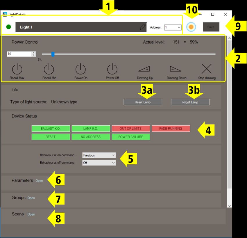
User manual
                                                                KNX-DALI Gateway EK-BG1-TP

2        Switching, display and connection elements

    No.    Description                          Notes
    1      KNX bus line connection terminal
    2      KNX programming button
                                                Indicates when the device is in programming
    3      KNX programming LED                  mode (permanently on) or when the connection
                                                with the KNX bus is missing (flashing)
    4      230V AC power connection terminals
                                                The two terminals are completely equivalent.
    5      Terminals for the DALI bus line      The polarity indicated is relative to the internal
                                                power supply.
    6      Ethernet port
                                                Indicates the presence of the supply voltage on
    7      DALI bus power supply LED
                                                the DALI bus
                                                Indicates communication activity in progress on
    8      DALI bus communication LED
                                                the DALI bus
                                                Indicates the presence of the power supply
    9      Logic power indicator LED
                                                voltage for the internal logic of the device.
                                                When steadiliy lit, indicates a communication
                                                fault or the presence of an error module on the
    10     Error on DALI bus indicator LED      DALI bus; when blinking, indicates that a scan
                                                for already assigned units on the bus is in
                                                progress.
                                                Indicates a request for DHCP assignment in
    11     DHCP indicator LED                   progress (flashing) or successful IP assignment
                                                (fixed)
    12     Membrane keys                        Send an On / Off broadcast command

Rev. 1.3 - 01/04/2021
© EKINEX S.p.A. - All rights reserved                                                        Pag. 5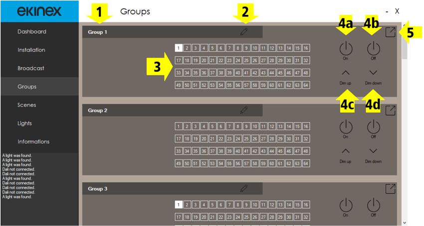
User manual
KNX-DALI Gateway EK-BG1-TP
3 Configuration and commissioning
Device configuration requires the following tools or files:
PC with Ethernet / WiFi connection
ETS software tool
APEKBG1TP.knxprod application program for the ETS tool (can be downloaded directly in ETS via the
ekinex product catalog)
CGEKBG1TP application software to carry out the gateway configuration
It is also necessary to have the following information handy:
[if DHCP mode is not used] Physical parameters of communication on the Ethernet network (IP
address, subnet mask, gateway)
Knowledge of the automation project configuration carried out with ETS, in particular the
communication objects and the group addresses used to interface with the devices in the DALI
subsystem.
The configuration and commissioning activities of the ekinex® gateway require specialist
skills on the KNX network and knowledge of the specific automation project carried out with
i ETS. To acquire these skills it is essential to participate in courses organized at KNX
certified training centers. For more information: www.knx.it.
4 Using the configuration software
The ekinex® CGEKBG1TP configuration software allows you to perform the following operations in a simple
and intuitive way:
choice of communication parameters on the Ethernet network;
management and update of all gateway settings, in addition to the parameters of (maximum) 64 lamps,
16 groups and 16 complex scenes;
download of updated firmware.
As a first step to perform the configuration, the device must be connected via an Ethernet cable to an existing
LAN network or directly to a PC whose network parameters have been appropriately configured.
The initial default IP of the device, according to the factory configuration, is 192.168.1.99.
This value can be changed:
By setting a new IP via KNX via the ETS application
By setting the IP assignment via DHCP1 (as described below).
The variation of the IP address must obviously be made with the device already connected.
In any case, at any time it is possible to read the IP currently assigned to the device (and the other network
parameters) via ETS or via KNX, reading the following communication objects:
1Note: to prevent the device from being assigned a new IP with each new reconnection to the LAN, it is
advisable to set (if the router or DHCP server allows it) the IP reservation based on the MAC address of the
devices.
Rev. 1.3 - 01/04/2021
© EKINEX S.p.A. - All rights reserved Pag. 6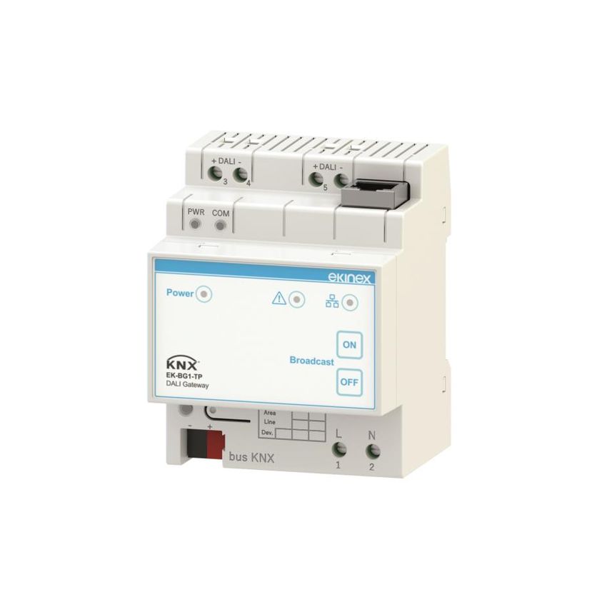
User manual
                                                                               KNX-DALI Gateway EK-BG1-TP

                                        IP Address               C.O. #5
                                        Subnet mask              C.O. #6
                                        Gateway address          C.O. #7

4.1     Dashboard
When the configurator starts, the first page shown is the dashboard. The screen is divided into 4 sections
marked by numbers in the figure below.

      1. The part regarding the IP connection. You can select whether to use the default IP or any IP specified
         by the user via ETS or assigned via DHCP, if known (1a). Once the IP to be used has been chosen,
         the connection can be attempted using the button (1b); if the IP is correct, the connection indication
         will appear in (1c) after a few seconds.
      2. The section where you can specify whether to use an IP from DHCP or fixed (2a). In both cases, the
         current address data is displayed in (2b)
         If the gateway fails to find a dynamic IP via DHCP, the default IP is assigned.
      3. The section showing some information relating to the KNX (3a / 3b) and DALI (3c / 3d) buses, as well
         as the device status. Using the button (3b) it is possible to activate the programming status for ETS; if
         the "DALI ready" status (3c) is active (green) it is possible to access the remaining pages of the
         configurator.
      4. The section dedicated to updating the device firmware online; by selecting an update file (with the
         button (4a) or via drag & drop), provided by ekinex, it is possible to update the firmware following
         improvements or troubleshooting. Once the firmware has been updated, in the event of malfunctions,
         it is possible to return to the previous version using the button (4b).

Rev. 1.3 - 01/04/2021
© EKINEX S.p.A. - All rights reserved                                                                       Pag. 7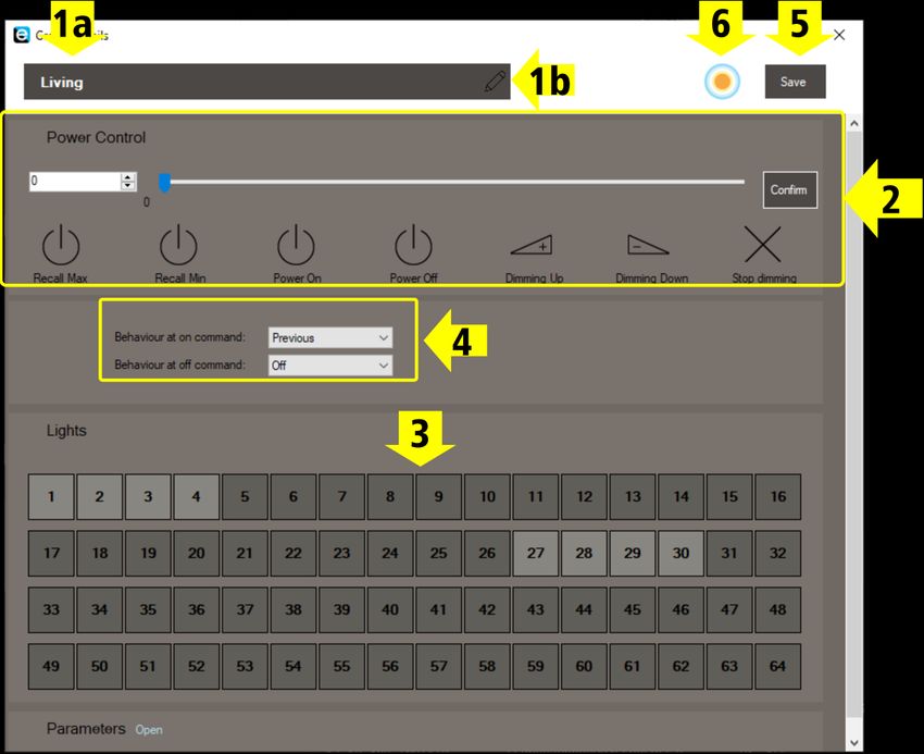
User manual
KNX-DALI Gateway EK-BG1-TP
4.2 Installation
The "Installation" page is used for the configuration of the system on the DALI side, ie for the addressing and
setting of all the connected DALI units.
The page is shown as in the following image:
These are the available choices:
Post-installation search (3a) - look for any new devices added since the last configuration and assign
them an address;
New search (3b) - clears the current list of devices and starts a new search and address scan from
scratch;
Scan bus (3c) - search for any new, previously addressed devices which were offline and then returned
online;
Reset DALI configuration (3d) - clears the current list of devices without performing a new scan.
By pressing the "New search" button, all the units connected on the DALI bus (1a) will appear as shown in the
figure. To stop the search, click on the "X" button on the left (1b):
Rev. 1.3 - 01/04/2021
© EKINEX S.p.A. - All rights reserved Pag. 8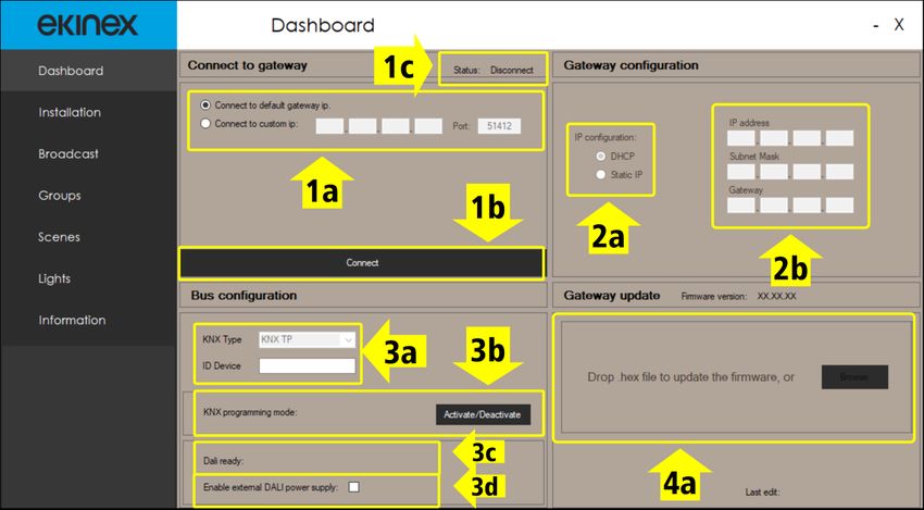
User manual
KNX-DALI Gateway EK-BG1-TP
At the end of the search, you can start a new search (2a).
For each unit found, from this screen you can:
Assign an identification name (2c)
Assign the DALI address (2d), then confirm it with (2e)
Activate an intermittent flashing, lasting a few seconds, which allows you to physically locate the lamp
(2f), provided that it supports the identification feature.
The detailed configuration of the detected units is carried out on the "Lights" page (see below).
4.3 Broadcast
The "Broadcast" page is used to send commands to all connected DALI units.
On the Broadcast page there is a single panel with the controls illustrated below; the controls refer to the entire
set of connected lamps.
Since the description of these commands (with the same graphic setting) also applies exactly to the case of
individual units, the available commands are listed below in detail.
With reference to the figure above, the commands that can be used for the individual lights, groups, and scenes
are as follows.
Rev. 1.3 - 01/04/2021
© EKINEX S.p.A. - All rights reserved Pag. 9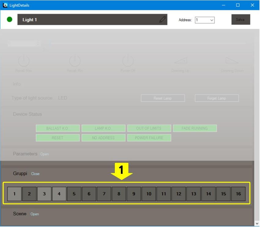
User manual
KNX-DALI Gateway EK-BG1-TP
Note: the following refers to a set of lamps (group or broadcast), but the description is also applicable to the
case of a single lamp.
Power control: the selector (1) and the slider (2) allow you to select a value between 0 and 254, or
0% -100%, and send it to all the lights involved.
In this case the lamps will follow the fade time set on the "Lights" page (see).
In the case of groups and broadcast it will be necessary to press the "Confirm" button (4) to validate
the change, while in the case of a single lamp the transmission will be immediate.
The Recall Max (3a) and Recall Min (3b) buttons will bring each lamp to its maximum / minimum
brightness value; in this case the fade time will be the minimum allowed (200 ms) and will be the
same for all, but the level for each lamp will be the one set in the "Lights" page (see).
The Power Off button (3c) will bring all the lamps to the brightness value 0; also in this case the fade
time will be the minimum allowed (200 ms).
The Dimming Up (3d) and Dimming Down (3e) buttons will vary the brightness of the lamps by a
step as set on the "Lights" page (see) via the "fade rate" parameter. The fade time for the step is
always the fixed time of 200 ms.
Button (2) opens a panel for the setting of lamp paramenters, described below.
4.3.1 Lamp parameters
This panel allows to set the parameters related to the brightness levels and dimming times of the lamps.
The parameters that can be set are:
The maximum brightness value
The minimum brightness value
The Power on value, which is the value used when the DALI bus connection is reestablished.
If "Power on" is 255, in the event of a reset the lamp will revert to the last valid brightness value
received previously.
The System failure value, ie the value used in the event of a DALI bus failure. If "system fail" is 255,
the lamp will have no reaction in the event of a bus failure
Rev. 1.3 - 01/04/2021
© EKINEX S.p.A. - All rights reserved Pag. 10User manual
KNX-DALI Gateway EK-BG1-TP
The Fade on time. This time is used for dimming commands (both relative and absolute) given via
KNX and for the dimming command given by the configurator via slider or absolute value
The Fade rate, ie the frequency of the steps with which the dimming ramps are generated
IMPORTANT: Remember that any changes do not take effect until they are confirmed with the "Save" button
(2)!
4.4 Groups
The groups page contains 16 panels (one for each of the configurable groups), through which it is possible to:
Assign a name to the group (2);
Display a synoptic of the lamps assigned to the group (3);
Send commands to all the lamps belonging to the group (4); the commands are those previously
described. Both the “On” and “Off” commands will behave in the fashion set in the group configuration
panel.
Access the group configuration panel (5).
Rev. 1.3 - 01/04/2021
© EKINEX S.p.A. - All rights reserved Pag. 11User manual
KNX-DALI Gateway EK-BG1-TP
The group configuration panel looks like this:
Through this panel following operations are possible:
Change the name of the group (1b);
Send commands to all the lamps belonging to the group (2);
Assign each of the 64 available lamps to the group (3).
The assignment does not take into account the actual presence of the assigned lamps among those
detected;
Configure the behavior when receiving the On / Off commands via the KNX bus (4); the choices are
Previous / Max for “On” and Min / Off for “Off”.
These commands can also be issued through the corresponding buttons on panel (2).
Open the Group Color Details panel (6).
The control panels are those previously described.
Once any group setting has been changed, the "Save" key (5) will be enabled; pressing it, the new parameters
will be sent on the DALI bus to the lamps involved.
Important notice: if group dimming is used from KNX, it is very highly recommended to set the same fade time
value for all units belonging to the same group!
Rev. 1.3 - 01/04/2021
© EKINEX S.p.A. - All rights reserved Pag. 12User manual
KNX-DALI Gateway EK-BG1-TP
4.4.1 Group Colour Details panel
This panel contains the settings for “Tunable White” devices (Cold plus Warm white tones)
The “Colour Control” section (1) allows direct control of the color temperature of the light source; the “Info”
section lists the information returned by the device.
The “Parameters” section (3) allows the setting of the color temperature parameters of the lamp.
Coolest Level sets the lowest allowable value for the color temperature
Warmest Level sets the highest allowable value for the color temperature
Power on level sets the value for the color temperature at start-up
System Failure sets the color temperature value to be set when the bus is not present.
After any variation, the parameters are saved through button (4).
Rev. 1.3 - 01/04/2021
© EKINEX S.p.A. - All rights reserved Pag. 13User manual
KNX-DALI Gateway EK-BG1-TP
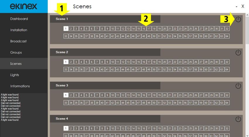
4.5 Scenes
The "Scenes" page contains 16 panels (one for each of the configurable scenes), through which it is possible
to:
Display an overview of the lamps involved in the scene (2);
Command the activation of the scene (3).
The overview (2) is only for display: the lamp / scene combination is not set on this page but rather on the
pages of the individual lamps (where the relative brightness value is also set).
Scene names are not customizable.
4.6 Lights
The "Lights" page displays a series of subpanels corresponding to each of the lamps identified and addressed
on the DALI bus.
Rev. 1.3 - 01/04/2021
© EKINEX S.p.A. - All rights reserved Pag. 14User manual
KNX-DALI Gateway EK-BG1-TP
The main information and operations relating to each lamp are shown on each of the subpanels:
The name of the unit (1a), which can be modified using the specific button (1b);
The "online" status of the lamp (1c);
The DALI address and the current brightness value (2);
The “Lamp seek” button (3).
Through the button (5) it is possible to expand the panel and view the following additional information (7) and
commands (8):
The groups to which the lamp belongs;
The scenes for which the lamp is configured;
A series of annunciators which, if displayed in red, indicate any error conditions;
The On/Off command buttons.
In particular, the meaning of the error states is as follows:
Ballast K.O. Generic problem on the lamp driver
Lamp K.O. Generic problem on the light source
A value above the maximum level or below the minimum level has been
Out of limits
sent
A lamp is being dimmed with commands that use a fade time value other
Fade running
than 200ms
Reset The lamp is reset to the factory values
No address The lamp is not addressed
Power Failure Power supply problem
For each lamp, it is possible to access a detail page via the icon/button (4) at the top right.
Rev. 1.3 - 01/04/2021
© EKINEX S.p.A. - All rights reserved Pag. 15User manual
KNX-DALI Gateway EK-BG1-TP
This page contains further information and operations; some elements have already been illustrated, such as
the control panel (2), the status panel (4), the On/Off values (5) and the lamp parameters (6).
In addition to these, others are available:
The name panel (1), which, in addition to the description, also allows to change the assigned DALI
address;
The "Reset lamp" (3a) button, which allows to reset the lamp parameters to the default values
The "Forget lamp" (3b) button, which allows to return the lamp to the unaddressed status;
The button used to open the panel used to set the color temperature parameters for the lamp (10)
The "Save" button (9), which allows all changes made to the parameters to be confirmed and saved.
Panels (6), (7) and (8) are individually expandable and are described below.
Rev. 1.3 - 01/04/2021
© EKINEX S.p.A. - All rights reserved Pag. 16User manual
KNX-DALI Gateway EK-BG1-TP
4.6.1 Parameters
On this panel the lamp parameters can be set; the panel has exactly the same structure as the one described
for Broadcast operations (refer to Section 4.3.1Errore. L'origine riferimento non è stata trovata.).
4.6.2 Groups
On this panel it is possible to define which groups every lamp is associated with, by selecting the respective
boxes.
Remember that any changes do not take effect until they are confirmed with the "Save" button!
Rev. 1.3 - 01/04/2021
© EKINEX S.p.A. - All rights reserved Pag. 17User manual
KNX-DALI Gateway EK-BG1-TP
4.6.3 Scenes
In this panel it is possible to define which of the 16 possible scenes the lamp in question is associated to and
what value it correspondingly takes.
Remember that any changes do not take effect until they are confirmed with the "Save" button!
4.6.4 Lamp colour details
On this panel the color temperature parameters for “Tunable white” type lamps can be set; the panel has
exactly the same structure as the one described for lamp groups (refer to Section 4.4.1Errore. L'origine
iferimento non è stata trovata.).
Rev. 1.3 - 01/04/2021
© EKINEX S.p.A. - All rights reserved Pag. 18User manual
KNX-DALI Gateway EK-BG1-TP
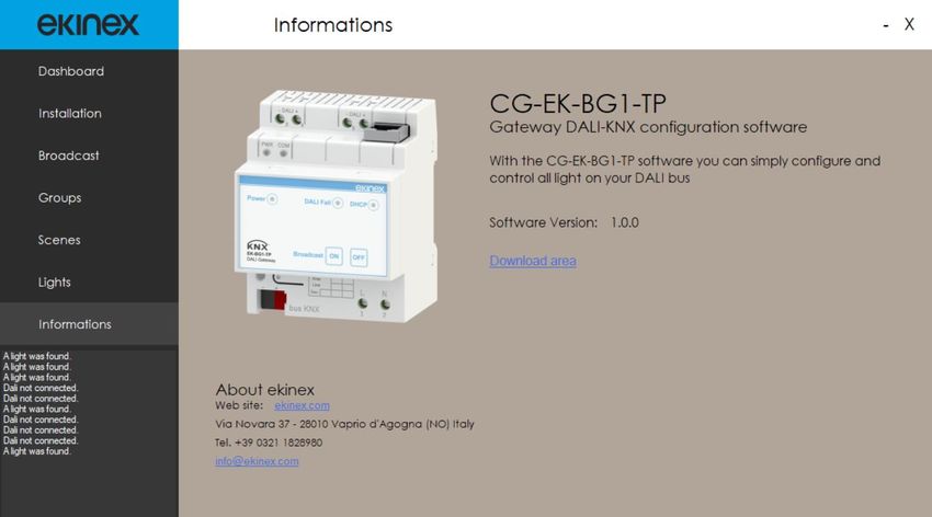
4.7 Information
This panel shows information on the configuration program, including the version and the link for downloading
any more updated versions.
Rev. 1.3 - 01/04/2021
© EKINEX S.p.A. - All rights reserved Pag. 19User manual
KNX-DALI Gateway EK-BG1-TP
5 ETS application: Parameters
5.1 Application program structure
The tree structureof the application program includes the following items:
Info on EK-BG1-TP
Generale
Behavior
IP settings
5.2 Tab: Info on EK-BG1-TP
This page is for information only and does not contain parameters to be set. The information shown is:
© Copyright ekinex S.p.A. 2019
Application software for ETS5
Version 1.00 (or later)
DALI - KNX Gateway
ekinex S.p.A.
Via Novara 37
I-28010 Vaprio d’Agogna (NO)
www.ekinex.com
info@ekinex.com
5.3 Tab: General
Following settings are found in the General tab:
Behavior
IP settings
5.3.1 Tab: General - Behaviour and alarms
In the Behavior tab, all behaviors relating to bus events are configured and alarms are managed.
Parameter name Condition Values
No Change
Behavior at Power On
Previous
When the gateway is not powered, all the lamps on the DALI bus set the
brightness to the system failure value.
This parameter tells the gateway what behavior to take on startup: whether to keep
the lamps at the same value, or return them to the last active value before
switching off.
Rev. 1.3 - 01/04/2021
© EKINEX S.p.A. - All rights reserved Pag. 20User manual
KNX-DALI Gateway EK-BG1-TP
Parameter name Condition Values
No Change
DALI broadcast on
Behavior on KNX bus on
DALI broadcast off
DALI custom value
DALI custom value Behavior on KNX bus on = DALI custom value 0%..100% [100%]
No Change
DALI broadcast on
Behavior on KNX bus off
DALI broadcast off
DALI custom value
Behavior on KNX bus off =
DALI custom value 0%..100% [100%]
DALI custom value
00:00:00 … 18:12:15
Delay after KNX bus on
[00:00:04] (hh:mm:ss)
The parameter sets the delay between the moment in which the KNX bus line is
powered and the moment in which the device starts transmitting data (sending status
feedback, regulation output, etc.).
Send on Change
Transmission of light status Send on Request
Send on Change and after bus on
Disable
Transmission of dimming mode
Change of value
Transmission of dimming mode =
Minimum value change for transmission 2%…100% [100%]
Change of value
DALI bus alarm Disable / Enable
If there are problems with the power supply of the DALI bus, an alarm message is
sent on the KNX bus
DALI Diagnostic alarms Disable / Enable
The parameter enables a communication object in transmission mode which allows
to diagnose if there are lamps on the DALI bus in an alarm state.
5.3.2 Tab: General - IP settings
In the IP settings tab all rettings related to the Ethernet interface are managed.
Parameter name Condition Values
DHCP Yes / No
IP Address DHCP = No IP values 0..255 [0.0.0.0]
This data is composed of four numeric fields corresponding to the four parts of the
IP address.
Subnet Mask DHCP = No IP values 0..255 [0.0.0.0]
This data is composed of four numeric fields corresponding to the four parts of the
IP subnet mask.
Gateway DHCP = No IP values 0..255 [0.0.0.0]
This data is composed of four numeric fields corresponding to the four parts of the
IP address.
Rev. 1.3 - 01/04/2021
© EKINEX S.p.A. - All rights reserved Pag. 21User manual
KNX-DALI Gateway EK-BG1-TP
Parameter name Condition Values
Port address for DALI configuration 0..65535 [51412]
5.4 Tab: Groups
In the Groups tab, those groups are selected whose communication objects should be displayed.
Groups of interest are selected from a complete list; initially, all groups are disabled, therefore the
Communication Object list will only contain those objects pertaining to Scenes and Broadcast.
Every line has a selector to enable the corresponding group; a second selector on each line identifies the
corresponding group as being capable of Tunable White features.
5.5 Tab: ECG
In the ECG tab (Electronic Control Gear) the units are selected whose communication objects should be
displayed.
Units of interest are selected from a complete list; initially, all units are disabled, therefore the Communication
Object list will only contain those objects pertaining to Scenes and Broadcast.
Every line has a selector to enable the corresponding unit; a second selector on each line identifies the
corresponding unit as being capable of Tunable White features.
6 ETS Application: Communication objects
6.1 Communication objects - General
Object name Conditions Dim. Flags DPT C.O. #
FW version 2 Byte CR-T- [217.001] DPT_Version 1
[238.600]
DALI diagnostics alarm DALI diagnostic alarm = Enabled 1 Byte C--T- 3
DPT_DALI_Diagnostic
Transmitted when the alarm state of a DALI unit changes
Testo allarmi 14 Bytes CR-T- [16.0] DPT_String_ASCII 4
Text message for technical alarms.
Allowed values:
“ALARM E00“ No units addressed on the bus
“ALARM E01” Group command failed (if a value is sent to a group of lights, check if the lamps belonging
to that group have reacted correctly)
“ALARM E02” Error sending the message on the DALI bus
6.2 Communication objects - IP settings
Object name Conditions Dim. Flags DPT C.O. #
[24.001]
IP Address (variable) CR-T- 5
DPT_VarString_8859_1
[24.001]
Subnet mask (variable) CR-T- 6
DPT_VarString_8859_1
[24.001]
Gateway address (variable) CR-T- 7
DPT_VarString_8859_1
Rev. 1.3 - 01/04/2021
© EKINEX S.p.A. - All rights reserved Pag. 22User manual
KNX-DALI Gateway EK-BG1-TP
Object name Conditions Dim. Flags DPT C.O. #
6.3 Communication objects - DALI groups
According to the DALI standard, units can be grouped into up to 16 groups.
Data in the table below are to be considered repeated for each of the 16 groups.
Object name Conditions Dim. Flags DPT C.O. #
Gn - On/Off command 1 bit C-W-- [1.001] DPT_Switch 8, 16,.. 128
Recalls the maximum / minimum value of the group lights in the shortest possible time (normally 0.2 s).
Gn – Relative
4 bit C-W-- [3.007] DPT_Control_Dimming 9, 17 … 129
Dimming
Relative dimming command (increase / decrease) for the lights belonging to the group.
Relative dimming uses the value set as unit fade time to make the transition between the current value and
the setpoint value.
Gn – Absolute
1 Byte C-W-- [5.001] DPT_Scaling 10,18 … 130
Dimming
Absolute dimming command for the lights belonging to the group..
Absolute dimming uses the value set as unit fade time to make the transition between the current value
and the setpoint value.
The absolute value sent as a percentage will be converted on a scale from 0 to 254.
Gn –On/Off Status 1 bit CR-T- [1.001] DPT_Switch 11, 19 … 131
Group status feedback.
This object remains unchanged until all the lamps within this group have changed status.
For instance, assuming that at start-up all the lamps are off, this object is sent to "Off"; it will then remain
unchanged until all the lamps have changed state to On. At this point, this object will be sent with value
"On".
Gn – Status Alarm 1 bit CR-T- [1.005] DPT_Alarm 12,17…87
Sent if at least one lamp within the group is in alarm
Gn – TW - Absolute Show Group x = true
1 Byte -WC--- [5.001] DPT_ Scaling 13, 21 … 133
dimming percentage Tunable White = True
Sets the color temperature from 0% to 100% with absolute value command.
The 0%-100% interval is automatically converted to the corresponding Kelvin value.
Gn – TW - Relative Show Group x = true
4 bit -WC--- [3.007] DPT_ Control_Dimming 14, 22,… 134
dimming percentage Tunable White = True
Changes the color temperature of the group from 0% to 100% with relative command.
Gn – TW - Absolute Show Group x = true [7.600]
2 Byte -WC--- 15, 23, …135
dimming Kelvin Tunable White = True DPT_temperature_Color_Kelvin
Sets the color temperature of the group with absolute value command, directly specifying the Kelvin value.
6.4 Communication objects - DALI unit
According to the DALI standard, up to 64 units can be connected on the same line;
data in the table below are to be considered repeated for each of the 64 units.
Object name Conditions Dim. Flags DPT C.O. #
ECGx -
1 bit C-W-- [1.001] DPT_Switch 136, 146 …766
On/Off command
Recalls the maximum / minimum value of the group lights in the shortest possible time (normally 0.2 s).
Rev. 1.3 - 01/04/2021
© EKINEX S.p.A. - All rights reserved Pag. 23User manual
KNX-DALI Gateway EK-BG1-TP
Object name Conditions Dim. Flags DPT C.O. #
ECGx –
4 bit C-W-- [3.007] DPT_Control_Dimming 137, 147 …767
Relative Dimming
Relative dimming command (increase / decrease) for the unit.
Relative dimming uses the value set as unit fade time to make the transition between the current value
and the setpoint value.
ECGx – [5.001]
1 Byte C-W-- 138, 148 …768
Absolute Dimming DPT_Scaling
Absolute dimming command for the unit.
Absolute dimming uses the value set as unit fade time to make the transition between the current value
and the setpoint value.
The absolute value sent as a percentage will be converted on a scale from 0 to 254.
ECGx –
1 bit C-W-- [1.001] DPT_Switch 139, 149 …769
Status On/Off
If the brightness value of the unit is different from zero, the "On" status will be sent on the KNX bus,
otherwise the "Off" status will be sent.
ECGx – Condizione di invio dimming
1 bit C-W-- [1.001] DPT_Switch 140, 150 …770
Status of dimming value mode = Enable
The brightness value is sent only if the dimming sending condition is respected.
At the time of reading, the dimming value between 0-254 will be converted into a percentage 0-100%
ECGx –
1 bit CR-T- [1.005] DPT_Alarm 141, 151 …771
Status Alarm
If the unit has one of the "BALLAST K.O." or "LAMP K.O." alarms active, an value = 1 is sent on the bus,
otherwise = 0
ECGx –
Show ECG x = true
TW - Absolute dimming 1 Byte -WC--- [5.001] DPT_ Scaling 142, 152 …772
Tunable White = True
percentage
Sets the color temperature of the lamp from 0% to 100% with absolute value command.
The 0%-100% interval is automatically converted to the corresponding Kelvin value.
ECGx –
Show ECG x = true
TW - Relative dimming 4 bit -WC--- [3.007] DPT_ Control_Dimming 143, 153 …773
Tunable White = True
percentage
Changes the color temperature of the lamp from 0% to 100% with relative command
ECGx –
Show ECG x = true [7.600]
TW - Absolute dimming 2 Byte -WC--- 144, 154 …774
Tunable White = True DPT_temperature_Color_Kelvin
Kelvin
Sets the color temperature of the lamp with absolute value command, directly specifying the Kelvin value.
ECGx – Show ECG x = true [7.600]
2 Byte C-RT-- 145, 155 …775
Status of TW value Tunable White = True DPT_temperature_Color_Kelvin
Returns the color temperature value of the lamp in Kelvin units.
6.5 Communication objects - DALI Scenes
According to the DALI standard, each of the units can be assigned to one of the maximum 16 scenes available.
For compatibility with the KNX standard, we have chosen to be able to control these 16 scenes either with a
DPT_SceneNumber object with values from 0 to 15, or with the single 1-bit communication objects.
In the table below, the 1-bit activation object is to be considered repeated for each of the 16 scenes.
The KNX "Scene learning" command is not implemented; the brightness values associated with the scene are
to be programmed through the configurator.
Rev. 1.3 - 01/04/2021
© EKINEX S.p.A. - All rights reserved Pag. 24User manual
KNX-DALI Gateway EK-BG1-TP
Object name Conditions Dim. Flags DPT C.O. #
[17.001]
DALI scene command 1 Byte C-W-- 776
DPT_SceneNumber
Value between 0 and 15 (included)
Sn - Activation 1 bit C-W-- [1.001] DPT_Switch 777...792
6.6 Communication objects - DALI Broadcast
The broadcast commands described below are used to control all the units present on the DALI bus.
Object name Conditions Dim. Flags DPT C.O. #
Broadcast -
1 bit C-W-- [1.001] DPT_Switch 793
On/Off command
Recalls the maximum / minimum value of all lights in the shortest possible time (normally 0.2 s).
Broadcast – [5.001]
1 Byte C-W-- 794
Absolute Dimming DPT_Scaling
Absolute dimming command for all connected units.
Absolute dimming uses the value set as unit fade time to make the transition between the current value
and the setpoint value.
The absolute value sent as a percentage will be converted on a scale from 0 to 254.
Broadcast – [3.007]
4 bit C-W-- 795
Relative Dimming DPT_Control_Dimming
Relative dimming command (increase / decrease) for all connected units.
Relative dimming uses the value set as unit fade time to make the transition between the current value
and the setpoint value.
Broadcast –
TW - absolute dimming 1 Byte C-W-- [5.001] DPT_ Scaling 796
percentage
Sets the color temperature of all lamps from 0% to 100% with absolute value command.
The 0%-100% interval is automatically converted to the corresponding Kelvin value.
Broadcast –
TW - relative dimming 4 bit C-W-- [3.007] DPT_Control_Dimming 797
percentage
Changes the color temperature of all lamps from 0% to 100% with relative command
Broadcast –
[7.600]
TW - Absolute dimming 2 Byte C-W-- 798
DPT_temperature_Color_Kelvin
Kelvin
Sets the color temperature of the lamp with absolute value command, directly specifying the Kelvin value.
Rev. 1.3 - 01/04/2021
© EKINEX S.p.A. - All rights reserved Pag. 25User manual
KNX-DALI Gateway EK-BG1-TP
7 Warnings
Assembly, electrical connection, configuration and commissioning of the appliance can only be
carried out by specialized personnel in compliance with the applicable technical standards and the
laws in force in the respective countries
The opening of the device housing determines the immediate interruption of the warranty period
In the event of tampering, compliance with the essential requirements of the applicable directives for
which the appliance has been certified is no longer guaranteed
Faulty ekinex® KNX devices must be returned to the manufacturer at the following address:
EKINEX S.p.A. - Via Novara 37, I-28010 Vaprio d'Agogna (NO)
8 Other information
This application manual is intended for installers, system integrators and designers.
For more information on the product, you can contact ekinex® technical support at the e-mail
address:
support@ekinex.com
or consult the website www.ekinex.com .
KNX® and ETS® are registered trademarks of the KNX Association cvba, Brussels.
© EKINEX S.p.A. The company reserves the right to make changes to this documentation without notice.
Rev. 1.3 - 01/04/2021
© EKINEX S.p.A. - All rights reserved Pag. 26You can also read