A400GE-QDD 400GE Layer 1 BERT and KP4 FEC Multiport Test System - Keysight
←
→
Page content transcription
If your browser does not render page correctly, please read the page content below

A400GE-QDD 400GE Layer 1 BERT
and KP4 FEC Multiport Test System
Spend Less Time Finding Problems Highlights
and More Time Solving Them.
• Validate the BER performance of high-port-count devices with
4-ports of the A400GE-QDD 400GE BERT Layer 1 capabilities
Challenge: Finding Problems Faster and Earlier with Ixia’s KiOS multi-port browser application
in the 400GE Development Cycle • Find problems faster with KiOS browser-based single page
400 Gigabit Ethernet (GE) technologies based on the 56Gb application (SPA), system-view of all the BERT and FEC
statistics of all the lanes with 1x400GE, 2x200GE, 4x100GE,
electrical lane signaling rates have exponentially increased
and 8x50GE speed support
the level of complexity for the development of stable port
electronics in all networking devices. Now, the challenge • Measure BER and FEC performance in minutes, not hours—
evaluate new optical transceiver and copper cable
has become characterizing and quantifying the actual bit
interconnect BER at all Ethernet speeds simultaneously using
error ratio (BER) and forward error correction (FEC) the patented Enhanced BERT option
performance of silicon devices, application-specific
• Easily generate PASS/FAIL test reports, and perform long-
integrated circuits (ASICs), optical transceivers, fiber and
duration (timed tests) and stress tests using Ixia’s KP4 FEC
copper interconnects, and the port electronics of switches symbol bit error distribution analysis—excellent for catching
and routers. Identifying 400GE, 200GE, 100GE, and 50GE bursty and thermal errors that occur over time
BER and FEC performance problems quickly is critical as
• Simplify connection of A400GE-QDD to Keysight’s M8040A
answers are complex and time-consuming to solve. BERT analyzer and your development boards using our
optional host and module compliance boards, cables, and
Solution: A Simplified, Affordable BERT and adapter bundles
FEC Test System • Leverage field-proven technology that is an extension of our
two generations of 400GE QSFP-DD test systems
Ixia’s A400GE-QDD test system makes the challenge of
qualifying BER on 400GE electronics easier and
affordable. Whether validating chips, optical transceivers,
or port electronics, the A400GE-QDD is a dedicated BERT
and FEC test system with 56Gb electrical lane signaling per
port that gives you the ability to find a problem in minutes, not
hours. It shows a system-level view of the BER and FEC
performance of all the lanes, all at once, in real time.
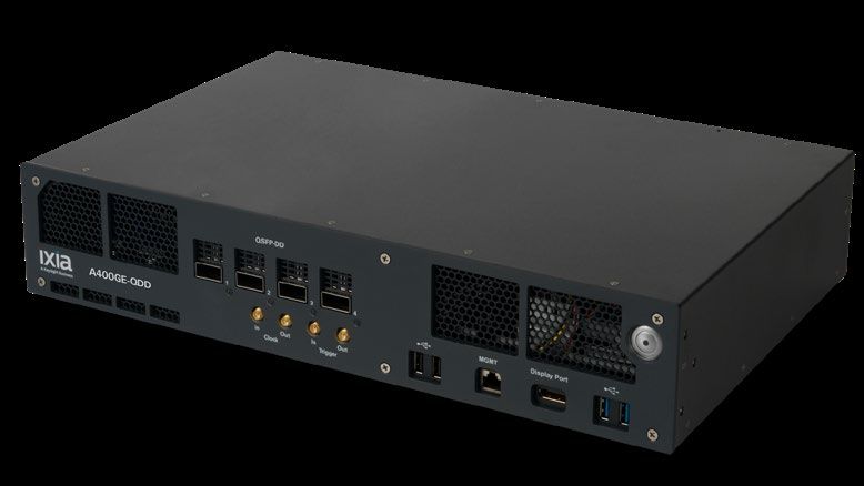
A400GE-QDD 400GE 4-port BERT
Layer 1 Chassis System
Find us at www.keysight.com Page 1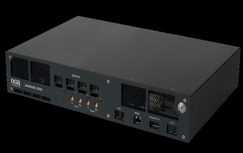
The A400GE-QDD is a compact BERT and FEC symbol error correction performance benchtop test
system. It may be installed on a rackmount as desired. The chassis is provided with the Layer 1 BERT
400GE test software, KiOS. The KiOS single-page application (SPA) uses the Google Chrome browser
implementation and makes set up so easy and fast, you can start testing and generating PASS/FAIL
test reports using your tolerance and limits within minutes. An optional RS-544 (KP4) FEC symbol error
correction test capability is available that simplifies FEC lanes testing, just as easily as Layer 1 BERT.
Ixia’s FEC codeword bit-error density distribution analysis (the FEC tail) shows the symbol error
performance and other advanced measurements when it comes time to perform long-duration and
stress tests; it cannot be made any easier.

The new patented Enhanced BERT option provides your development teams test capabilities to quickly
pinpoint problems and to validate and qualify excellent BER and FEC symbol error correction
performance:

• In-depth analysis of mismatched PAM4 multi-level signal errors
• SSPRQ100 pattern generation for 100G lane applications (please consult the factory for more
  information)
• BERT inferred FEC for faster analysis of FEC simultaneously over all Ethernet speeds
• A threshold bit-error tool to expose difficult-to-find bursty errors in PRBS patterns
A400GE-QDD chassis are available in two models:

• 2-port, 400GE Layer-1 BERT QSFP-DD test system (941-0080)
• 4-port, 400GE Layer-1 BERT QSFP-DD test system (941-0081)
  o Recommended for use with the Keysight M8040A BERT Analyzer

Pay as You Grow—2-port and 4-port Models, All Field Upgradeable
A400GE-QDD upgrades extend the reuse of the chassis system and improves your ROI. The ability to
upgrade A400GE-QDD to have it grow with your test needs is quick and easy. You can field-upgrade
any A400GE-QDD 2-port model to a full 4-port model. You can also field-upgrade any 2- or 4-port model
to add RS-544 FEC (KP4) test capability to enhance the built-in BERT features.

The A400GE-QDD can be upgraded in the field to support interconnection and synchronization with
Keysight’s M8040A high-performance BERT analyzer. The combined system is a symbol striped FEC-
aware physical layer BER tester. It is a solution for 400GE characterization and compliance test to
perform physical layer channel stress and impairment of a channel. Additionally, optical receiver stress
testing (ORST) may be performed.

Module and Host Compliance electrical breakout boards, cables, and adapter bundles make it easy to
connect the A400GE-QDD chassis to development systems to test chips, optical transceivers, and
direct attach copper (DAC) cables.

Mix and match whatever upgrades you require, whenever you need them. You are no longer stuck with
a dedicated piece of hardware with no hope of extending its capabilities. With A400GE-QDD, you have
the critical return on investment (ROI) for today’s and tomorrow’s test needs.

Find us at www.keysight.com                                                                                  Page 2
Key Features
• The A400GE-QDD is an excellent test platform for 400GE communications devices and
  hardware ports that use the 8x56Gb electrical interface with PAM4 encoding that is IEEE
  802.3bs and IEEE 802.3cd compliant.
• Ethernet speed support for: 1x400GE, 2x200GE, 4x100GE, and 8x50GE for BER and FEC
  symbol error correction performance measurements.
• A SPA, highly intuitive, fast, and efficient web-browser-driven UI supported by Google
  Chrome makes BER and FEC testing truly fast and simple.
• Report generation – as part of the test automation capabilities, you can instantly create pass
  and fail reports to your tolerance and maximum BER and/or FEC symbol error correction
  performance levels. Test reports and test time duration can use the KiOS default values or
  they can be quickly customized. Tests reports and configuration can be shared with peers for
  their test suites. Reports with failures are color-coded red for instant identification.
• The Layer 1 BERT capability is extended over previous generations of Ixia 400GE hardware
  with the ability to send PRBSQ patterns and it generates per-lane BER measurements and an
  array of additional statistics.
• PRBS pattern generation includes PRBS31Q, PRBS-23Q, PRBS-20Q, PRBS-15Q, PRBS-
  13Q, PRBS-11Q, PRBS-9Q, PRBS-7Q, and SSPRQ50.
• Hardware Clock IN and Clock OUT interface to receive a clock in from an external device, or
  to output the clock from the A400GE-QDD chassis.
• +/- 100 PPM line frequency adjustment that is applied to all enabled ports across the
  A400GE-QDD chassis system.
• Support for optical transceiver and copper cable interconnects.
• Host QSFP-DD provides default and user-selectable Tx host equalization controls with user
  adjustable custom settings for all lanes, or on any individual lane.
• Common management interface specification (CMIS) support for v3.0 and v4.0, user
  selectable, or use the version auto-detection feature; CMIS is for optical transceivers and
  copper cables.
• Option for RS-544 (KP4) FEC test capability.
  o 400GE FEC symbol error distribution analysis with a comprehensive set of FEC corrected
    and uncorrected count and rate statistics including BER statistics for FEC analysis
    o Extensive per-port and per-lane statistics
    o Advanced measurements such as pre-FEC BER and frame loss ratio (FLR)
• Option for enhanced BERT and inferred FEC measurement capability. Evaluate new optical
  transceiver and copper cable interconnect BER at all Ethernet speeds simultaneously with the
  patented Enhanced BERT option:
    o Factory installed and field upgrade options (requires KiOS 3,0 software or higher version)
    o In-depth analysis of mismatched PAM4 multi-level signal errors,
    o SSPRQ100 pattern generation for 100G lane applications
    o BERT Inferred FEC for faster analysis of FEC over all Ethernet speeds
    o A threshold bit-error tool to expose difficult-to-find bursty errors in PRBS patterns.
• The 2-port model (941-0080) may be upgraded with a purchasable field upgrade to a 4-port
  model (941-0081) at any time

Find us at www.keysight.com                                                                        Page 3
• Both the 2-port and 4-port models can be upgraded in the field to support interconnection and synchronization with Keysight’s M8040A High Performance BERT analyzer; the combined system is a symbol striped FEC-aware physical layer BER tester; please see the ordering information section of this datasheet Single-Page Application User Interface The new KiOS, Ixia’s latest innovation in the user interface experience, is a SPA and is supported by the Google Chrome web browser. This makes the UI fast, and responsive. The setup of the BERT and FEC tests and the presentation of the test results is quick and easy. Within a few mouse clicks, a test is set up and in seconds, the results are only 1 or 2 mouse clicks away. Figure 1. KiOS main page – Overall port configurations, port/link status, and test mode set up. One-click zooms into any of the ports of interest. With KiOS, moving from test setup to a port or QSFP-DD host configuration, CMIS, and statistical interfaces is effortless. Seeing instant test results on one port or across multiple ports is simple. Using Chrome’s tiling feature, open multiple windows simultaneously to display different views of the test or configuration as desired. Use the “+” sign at the top of any column to expand the results for deeper analysis! Figure 2. BERT Stats page – All 8x50G lanes, PRBSQ Tx/Rx configuration, pattern lock status, BER statistics. Includes real-time start/pause/stop/clear controls. Ports 1 and 3 have a passive copper DAC installed. Find us at www.keysight.com Page 4
Figure 3. FEC Lanes Rx Stats page – All FEC lanes with PCS Lane Marker lock status, and BER statistics. Includes
real-time start/pause/stop/clear controls. Ports 1 and 3 have a passive copper DAC installed.

Figure 4. FEC Codeword Stats page – FEC port stats with advance measurements such as Pre-FEC BER, Frame
Loss Ratio. Lower half are the FEC codeword bit-error distribution analysis. Excellent tool for stress and long
duration tests. Includes real-time start/pause/stop/clear controls. Ports 1 and 3 have a passive copper DAC installed.

Find us at www.keysight.com                                                                                              Page 5
Figure 5. Pass/Fail test report – Indicates a failed test result based on the user-defined input where a fail is
generated when there is greater than 3 symbol errors in a codeword over a 3-minute line rate test. Ports 1 and 3
have a passive copper DAC installed.

Specifications
                                       A400GE-QDD                                          A400GE-QDD
 Product Description
                                          2-port                                              4-port

                                       Chassis Physical & Electrical Specifications

Part Numbers                             941-0080                                           941-0081
Physical
                       Native QSFP-DD MSA form factor compatible physical ports
Interfaces
Chassis                2-port chassis system, desktop or               4-port chassis system, desktop or
Configurations         rackmount, 2 RU                                 rackmount, 2 RU

                       •    Power ON/OFF button
                       •    1 LED per port
Chassis                •    Clock IN / OUT: 2 SMA female connectors
Connector              •    Trigger IN / OUT: 2 SMA female connectors
Systems                •    4 USB: (2) USB 2.0 (2) USB 3.0 compatible ports
                       •    1 RJ45: 1000/100/10Mbps Ethernet management port
                       •    1 Display Port, supports a maximum resolution of 4096 x 2304 @60Hz

Find us at www.keysight.com                                                                                        Page 6
A400GE-QDD A400GE-QDD
Product Description 2-port 4-port
• Frequency: 166.015625 MHz +/- 100 PPM
Chassis Clock IN • 50 ohm termination
– Electrical
Specifications • Minimum = 0.5 Vpk-pk = 0.18 Vrms (sine)
• Maximum = 3.0 Vpk-pk = 1.06 Vrms (sine)
Chassis Clock • Frequency: 166.015625 MHz +/- 100 PPM
OUT – Electrical • HCSL, 50 ohm
Specifications • VOH > 0.55 V, VOL < 0.15 V, Swing > 0.55 V
Hardware Trigger
IN / OUT – • Trigger In: 50 ohm termination; Minimum = -1.0 V, Maximum = +4.0 V, Swing > 0.2 V
Electrical • Trigger Out: HCSL, 50 ohm; VOH > 0.55 V, VOL < 0.15 V, Swing > 0.55 V
Specifications
• Operates on 100-240VAC, 50/60Hz:
Chassis System ° 8 Amps on 100-125VAC
Electrical Power ° 4 Amps on single phase, 200-240VAC
• A400GE-QDD chassis is shipped with (1 each) 100-125VAC North American power
cord. Options for international shipments are selected at the time of order placement.
Chassis System • 11.14” (L) x 17.4” (W) x 3.65” (H)
Dimensions • 283mm (L) x 442mm (W) x 92.65mm (H)
• Hardware only: 21.75 lbs. (9.87 kg)
Chassis System • Shipping: 30.49 lbs. (13.83 kg)
Weights • Includes rackmount slides, cable support bracket, power cord, accessories and
packaging
Temperature • Operating: 41°F to 95°F (5°C to 35°C)
(Ambient Air) • Storage: 41°F to 122°F (5°C to 50°C)
Humidity • Operating: 0% to 80%, non-condensing
(Ambient Air) • Storage: 0% to 80%, non-condensing
Regulatory IEC 60950-1, UL 60950-1, CSA C22.2 No.60950-1, IEC 62368-1, UL 62368-1, CSA
Compliance 62368-1, CE (LVD, EMC, RoHS), EN/IEC 55032, EN/IEC 55024, CFR 47, FCC Part
Specifications 15B, ICES-003, AS/NZ CISPR 32/24, KN32/35
Chassis System Specifications
• Layer 1 BERT test and measurement capability
• Latest version of the KiOS operating software
Chassis System
• Web browser user interface support via Google Chrome
• On-line, context-sensitive help
• Rest API and Python library
Find us at www.keysight.com Page 7A400GE-QDD A400GE-QDD
Product Description 2-port 4-port
• Automated pass/fail report generator
• CMIS support and QSDP-DD Tx tap controls
• Rackmount ears for 19” rackmount
• May be used on a benchtop with user-installed feet
• Cable support bracket
• 1x400GE
• 2x200GE break-out
Supported Port • 4x100GE break-out
Speed Modes • 8x50GE break-out
• All ports must be run at the same speed
• Compatible with QSFP-DD form factor optical transceivers and copper DACs
IEEE Interface
• IEEE 802.3bs 200GE & 400GE, 400GBASE-R
Protocols for
400GE • IEEE 802.3cd 50 Gb/s, 100 Gb/s, and 200 Gb/s Ethernet
Support for all QSFP-DD MSA compliant optical transceivers up to Power Class 7 with 14
watts of power consumption such as: 400GBASE-DR4, 400GBASE-FR4, 400GBASE-
LR8 and 400GBASE-SR8, plus other optical transceiver types (e.g., QSFP56), and AOCs.
Please consult the factory for specific transceiver support information. See Optical
Transceivers under the Ordering Information section of this data sheet.
Module Case Temperature Range
Module Power Class Ambient Temperature
Standard Extended Industrial
Optical
Transceiver
6 or below 5 °C to 35 °C
Support
7 or below 5 °C to 35 °C
7 or below 5 °C to 25 °C
QSFP-DD MSA case temperature ranges:
• Standard 0 °C to 70 °C
• Extended -5 °C to 85 °C
• Industrial -40 °C to 85 °C
400GBASE-CR8, passive, copper Direct Attached Cable (DAC) up to 3 meters in
Copper Cable length. Please consult the factory for longer lengths and information on Active Copper
Support Cable (ACC). See Copper Cables under the Ordering Information section of this
datasheet.
Common • v3.0 and v4.0, auto-detected or user selectable
Management
Interface • May be used with copper and optical interconnects
Find us at www.keysight.com Page 8A400GE-QDD A400GE-QDD
Product Description 2-port 4-port
Specification • Displays the management registers with human-readable values using clear, alpha-
(CMIS) numeric text
Chassis Feature Specifications
400GE native ports:
• Layer 1 unframed, BERT Tx and Rx capability, 26.5625 GBaud
• PRBS pattern support: PRBS31Q, PRBS-23Q, PRBS-20Q, PRBS-15Q, PRBS-13Q,
PRBS-11Q, PRBS-9Q, PRBS-7Q
Layer 1 BERT
• SSPRQ50 is supported on the Tx-side only
• User selectable, per lane PRBSQ pattern assignment
• Tx and Rx pattern inversion support
• Auto detect of Rx pattern, or discreet detection of selected pattern
• General controls: Start, Stop, and Clear
• Display: 8x50G lanes or 16x25G lanes
• Per lane indicators: Pattern Lock, PRBSQ Pattern transmitted, PRBSQ Pattern
Received
• Per lane BERT statistics:
° PAM4 Symbols Sent
° PAM4 Symbols Received
° PAM4 Symbol Errors Received
Layer 1 BERT
Statistics ° Mismatched 00's
° Mismatched 01's
° Mismatched 11's
° Mismatched 10's
° PAM4 Symbol Error Ratio
° Lost Lock Count
° Bit Error Ratio (BER)
° Symbol Error Ratio (SER) in 8x50G lane display mode only
° Transmit duration time
• Test automation capabilities
• Instantly create pass and fail reports to your tolerance and maximum BER and/or FEC
symbol error correction performance levels
Report Generator • Test reports and test time duration can use the KiOS default values or they can be
quickly customized
• Tests reports and configuration can be shared with peers for their test suites
• Reports with failures are color-coded red for instant identification
Find us at www.keysight.com Page 9A400GE-QDD A400GE-QDD
Product Description 2-port 4-port
Enhanced BERT Option - Feature Specifications
Requires the 905-1073 factory installed or the 905-1074 field upgrade option
• In-depth actual statistics and rates regarding mismatched 00’s, 01’s, 10’s, 11’s
• Real time inferred FEC statistics generated from L1 BERT PRBSQ patterns for all
Layer 1
Ethernet speeds on the port
Enhanced Bert
• Provides a user-defined receive burst error window size and burst threshold
Statistics
window for finding and measuring bursty errors when usinf PRBSQ patterns
• SSPRQ100 for SSPRQ transmit pattern for 100G serial electrical lane analuysis
(consult factory for more information)
Provides default and user-selectable pre-emphasis controls for the following:
• Ixia-derived default Tx tap settings are provided for electrical and optical media
• Tx Host SerDes controls and ranges:
Drive amplitude (233mV to 991mV)
Pre-Cursor (0 dB to -8.7 dB)
Pre-Cursor 2 (0 dB to -2.7 dB)
Post-cursor (0 dB to -8.4 dB)
Host QSFP-DD
Signal Controls • User adjustable, custom settings for: All lanes, any group of lanes, or on an individual
lane
• Module Control/Status menu with ModSelL, Power ON/OFF, ResetL for state of
module reset, LPMode for controls the module’s power mode, ModPrsL for module
presence indication, IntL to indicate a change in the module’s state, ModState to
indicate the state of the module
• The Rx side has an auto-adaptive CTLE (Continuous Time Linear Equalization) and
does not require manual tap settings
Transmit Line
Ability to adjust the line frequency over a range of +/- 100 PPM that is applied to all
Clock
enabled ports across the A400GE-QDD chassis system.
Adjustment
Transmit/Receive
Internal loopback may be set per port
Loopback
Forward Error Correction (FEC) Option - Feature Specifications
Reed-Solomon RS-FEC (544, 514), (KP4 FEC)
FEC Support • 400GE FEC codewords with scrambled idles
• 100GE FEC codewords with scrambled idles
• General controls: Start, Stop, and Clear
FEC Lanes Rx • Transmit duration time
Statistics • Display: 0-8 lanes each with MSB and LSB lane display
• Per lane indicators: PCS lane marker lock, PCS lane marker map, Virtual lane lock lost
Find us at www.keysight.com Page 10A400GE-QDD A400GE-QDD
Product Description 2-port 4-port
• Per lane PCS and FEC statistics:
° Relative Lane Skew (ns)
° PCS Lane Marker Error Count
° FEC Symbol Error Count
° FEC Corrected Bits Count
° FEC Symbol Error Ratio
° FEC Corrected Bit Ratio
• General controls: Start, Stop, and Clear statistics
• Transmit duration time
• FEC port statistics with count and rate:
° FEC Total Bit Errors
° FEC Max Symbol Errors
° FEC Corrected Codewords
° FEC Total Codewords
° FEC Frame Loss Ratio
° Pre-FEC Bit Error Rate
° FEC Rx Clock PPM Offset
° FEC Rx Link Loss
• FEC symbol bit error distribution analysis statistics:
° Tracks the distribution of the number of bit errors in FEC codewords. Symbol bit errors
are binned, from 0-15 errored bits in a FEC symbol with a resolution of 1-bit error, to
show a comprehensive distribution analysis of the symbol bit error distribution
FEC Codeword • Each bit error bin (0 through 15-bit errors per codeword) provides these statistics:
Statistics ° Total Codewords with 0 symbol errors
° Total Codewords with 1-15 symbol errors’ count
° Codeword symbol error rate
° Percentage of Total Codewords per symbol error bin
° Log 10 number of Total Codewords per symbol error bin
° Bit error count per symbol error bin
° Maximum number of bit errors per symbol error bin
° Average symbol bit error count
• FEC Uncorrectable Codeword: – greater than 15 symbol bit errors in a codeword
° Total Uncorrectable Codeword count
° Uncorrectable Codeword error rate
° Percentage of Total Uncorrectable Codewords
° Log 10 number of Total Uncorrectable Codewords
° Bi error count for Uncorrectable Codewords
° Maximum number of bit errors in Uncorrectable Codewords
° Average number of Uncorrectable Codewords
Find us at www.keysight.com Page 11A400GE-QDD A400GE-QDD
Product Description 2-port 4-port
• 400GE
Speed Support • 200GE (presented as 2x200GE per port for all ports on the chassis)
with the FEC
Option Enabled • 100GE (presented as 4x100GE per port for all ports on the chassis)
• 50GE (presented as 8x50GE per port for all ports on the chassis)
Synchronization to Keysight M4080A High-Performance Layer 1 BERT Analyzer Option
• Allows the A400GE-QDD chassis to be interconnected and synchronized to the
Keysight M8040A High Performance Layer 1 BERT Analyzer.
° The combined system is a symbol striped FEC aware physical layer Bit Error Rate
Tester
Synch to M8040A
Layer 1 BERT ° 400GE characterization and compliance test to perform physical layer channel stress
and impairment of a channel
Analyzer
° The effect of different types of jitter on the FEC tail can be analyzed
° Optical Receiver Stress Testing (ORST)
° Use the A400GE-QDD Host and Module Compliance board options for optical
transceiver, copper cable, and chip development system test
A400GE-QDD Port Host and Module Compliance Options
• Compliance Board Options are available for the following configurations
° Transmit only (Tx) Host Compliance Board with 16 total channels and attached 6” co-
axial cable with 2.92mm female connectors
° Receive only (Rx) Host Compliance Board with 16 total channels and attached 6” co-
axial cable with 2.92mm female connectors
QSFP-DD Host &
Module ° Module Compliance Board with Transmit (Tx) Host Compliance Board with 16 total
Compliance channels and attached 6” co-axial cable with 2.92mm female connectors and 16 each
options 3.5mm Coaxial adapters, M-M
° Module Compliance Board with Transmit (Tx) and Receive (Rx) Host Compliance
Boards with 32 total channels and attached 6” co-axial cable with 2.92mm female
connectors and 32 each 3.5mm Coaxial adapters, M-M
See QSFP-DD Host and Compliance Options under the Ordering Information
section of this datasheet.
Find us at www.keysight.com Page 12Application Support
A400GE-QDD
• Browser Support: The A400GE-QDD chassis and features are supported only on the Google Chrome
cross-platform browser. It is recommended to upgrade to the latest version for the browser.
• Other browsers such as Firefox, Safari, Internet Explorer, and Microsoft Edge may function at a sub-optimal
experience.
• KiOS: Operating system software for the A400GE-QDD Layer 1 BERT test 400GE wire-rate signal
generation and measurement analysis with optional support for Forward Error Correction measurement, and
synchronization with the Keysight M8040A High Performance BERT analyzer for physical layer applications.
• REST API: Support for overall test automation, managing the chassis, ports, logs, CMIS, license, test plans,
configuring tests, and accessing and gathering BERT and FEC measurement and statistics
• Python library: KiPY is a Python library that enables REST calls to KiOS on the A400GE-QDD to allow use
of a Python script to do the same things you do from the GUI, such as changing system settings, viewing
stats, and reading and writing CMIS registers
Ordering Information
A400GE-QDD Chassis Systems
941-0080
Ixia, A400GE-QDD, 2-port, 400GE/200GE/100GE/50GE Layer 1 BERT QSFP-QDD test system, fixed
chassis that includes the latest version of the KiOS software. The 4x100GE speed mode requires KiOS
version 2.1 software. The 2x200GE and the 8x50GE speed modes requires 2.2 KiOS version 2.2 software.
FEC measurement capability and synchronization to the Keysight M8040 BERT Analyzer are optional.
.
Find us at www.keysight.com Page 13941-0081 Ixia, A400GE-QDD, 4-port, 400GE/200GE/100GE/50GE Layer 1 BERT QSFP-QDD test system, fixed chassis that includes the latest version of the KiOS software. The 4x100GE speed mode requires KiOS version 2.1 software. The 2x200GE and the 8x50GE speed modes requires 2.2 KiOS version 2.2 software. FEC measurement capability and synchronization to the Keysight M8040 BERT Analyzer are optional. A400GE-QDD Chassis Port Field Upgrade 905-1050 Ixia, 2-port A400GE-QDD Option, FIELD UPGRADE, adds 2-ports to the A400GE-QDD 400GE Layer 1 BERT test system (941-0080) for a total of 4 ports. REQUIRES at the time of order placement the identification of the serial number of the specific A400GE-QDD unit where this option is to be installed A400GE-QDD Chassis FEC Options 905-1051 Ixia, A400GE-QDD, Option, KP4 FEC add-on test option, FACTORY INSTALLED for the A400GE-QDD 400GE Layer 1 BERT test systems (941-0080, 941-0081). This option is applied to all ports on the A400GE-DD fixed chassis L1 BERT test system. 905-1052 Ixia, A400GE-QDD, Option, KP4 FEC add-on option, FIELD UPGRADE for the A400GE-QDD 400GE Layer 1 BERT test systems (941-0080, 941-0081). REQUIRES at the time of order placement the identification of the serial number of the specific A400GE-QDD unit where this option is to be installed. This option is applied to all ports on the A400GE-QDD fixed chassis L1 BERT test system. A400GE-QDD Chassis Enhanced BERT Options 905-1073 Ixia, A400GE-QDD, Option, Enhanced BERT option, FACTORY INSTALLED for the A400GE-QDD 400GE Layer 1 BERT test systems (941-0080, 941-0081). This option provides in-depth analysis of mismatched PAM4 multi-level signal errors, SSPRQ100 pattern generation for 100G lane applications, BERT Inferred FEC for faster analysis of FEC over all Ethernet speeds, and a threshold bit-error tool to expose difficult-to-find bursty errors in PRBS patterns. Find us at www.keysight.com Page 14
905-1074

Ixia, A400GE-QDD, Option, Enhanced BERT option, FIELD UPGRADE for the A400GE-QDD 400GE Layer 1
BERT test systems (941-0080, 941-0081). This option provides in-depth analysis of mismatched PAM4
multi-level signal errors, SSPRQ100 pattern generation for 100G lane applications, BERT Inferred FEC for
faster analysis of FEC over all Ethernet speeds, and a threshold bit-error tool to expose difficult-to-find
bursty errors in PRBS patterns.

Chassis Options Synchronizd to M8040A BERT Analyzer
905-1053

Ixia, A400GE-QDD, Option, Synchronize to Keysight M8040A option, FACTORY INSTALLED for the
A400GE-QDD 400GE Layer 1 BERT test systems (941-0080, 941-0081). This option is applied to a
single M8040A high performance BERT unit to allow it to connect to a single A400GE-QDD test system.

905-1054

Ixia, A400GE-QDD, Option, Synchronize to Keysight M8040A option, FIELD UPGRADE for the
A400GE-QDD 400GE Layer 1 BERT test systems (941-0080, 941-0081). REQUIRES at the time of
order placement the identification of the serial number of the specific A400GE-QDD unit where this
option is to be installed. This option is applied to a single M8040A high performance BERT unit to allow
it to connect to a single A400GE-QDD test system.

Copper Cables
QSFP-DD-1M-CBL

QSFP-DD-to-QSFP-DD 400GE 400GBASE-R passive copper, Direct Attach Cable (DAC), point-to-point
cable, 1-meter length.

QSFP-DD-2M-CBL

QSFP-DD-to-QSFP-DD 400GE 400GBASE-R passive copper, Direct Attach Cable (DAC), point-to-point
cable, 2-meter length.

QSFP-DD-2-5M-CBL

QSFP-DD-to-QSFP-DD 400GE 400GBASE-R passive copper, Direct Attach Cable (DAC), point-to-point
cable, 2.5-meter length.

Optical Transceivers
QSFP-DD-DR4-XCVR

IXIA, QSFP-DD 400GE 400GBASE-DR4 pluggable optical transceiver, SMF (single mode), 1310nm,
500m reach (948-0050). This optical transceiver is compatible with all K400 QSFP-DD and AresONE
QSFP-DD fixed chassis systems.

Find us at www.keysight.com                                                                                   Page 15
QSFP-DD-FR4-XCVR

IXIA, QSFP-DD 400GE 400GBASE-FR4 pluggable optical transceiver, SMF (single mode), 1310nm,
2km reach (948-0052). This optical transceiver is compatible with all K400 QSFP-DD and AresONE
QSFP-DD fixed chassis systems.

QSFP-DD-LR8-XCVR

IXIA, QSFP-DD 400GE 400GBASE-LR8 pluggable optical transceiver, SMF (single mode), 1310nm,
10km reach (948-0053). This optical transceiver is compatible with all K400 QSFP-DD and AresONE
QSFP-DD fixed chassis systems.

QSFP-DD-SR8-XCVR

IXIA, QSFP-DD 400GE 400GBASE-SR8 pluggable optical transceiver, MMF (multimode), 850nm, 100m
reach (948-0051). This optical transceiver is compatible with all K400 QSFP-DD and AresONE QSFP-
DD fixed chassis systems.

QSFP-DD Host and Module Compliance Options
942-0130

Ixia, QSFP-DD 400GE Host Compliance Board (HCB) RX test adapter and cables: 16 each, attached,
high performance phase aligned 6" Coaxial Cables with Female 2.92 connectors. The HCB RX adapter
is compatible with the A400GE-QDD, 2-port, 400GE Layer 1 BERT QSFP-DD (941-0080), and the
A400GE-QDD, 4-port, 400GE Layer 1 BERT QSFP-DD (941-0081) test systems.

942-0131

Ixia, QSFP-DD 400GE Host Compliance Board (HCB) RX test adapter and cables: 16 each, attached,
high performance phase aligned 6" Coaxial Cables with Female 2.92 connectors. The HCB RX adapter
is compatible with the A400GE-QDD, 2-port, 400GE Layer 1 BERT QSFP-DD (941-0080), and the
A400GE-QDD, 4-port, 400GE Layer 1 BERT QSFP-DD (941-0081) test systems.

947-5090

Ixia, QSFP-DD 400GE Module Compliance Board (MCB) and TX Host Compliance Board (HCB) test
adapter, cables and connectors: 16 each, attached, high performance phase aligned 6" Coaxial Cables
with Female 2.92 connectors, with 16 each, 3.5mm Coaxial adapters, M-M. The MCB and HCB TX
Adapter are compatible with the A400GE-QDD, 2-port, 400GE Layer 1 BERT QSFP-DD (941-0080),
and the A400GE-QDD, 4-port, 400GE Layer 1 BERT QSFP-DD (941-0081) test systems.

947-5091

Ixia, QSFP-DD 400GE Module Compliance Board (MCB), TX and RX Host Compliance Board (HCB)
test adapters, cables and connectors: 16 each per adapter, attached, high performance phase aligned
6" Coaxial Cables with Female 2.92 connectors, with 32 each, 3.5mm Coaxial adapters, M-M. The
MCB, HCB TX and HCB RX adapters are compatible with the A400GE-QDD, 2-port, 400GE Layer 1
BERT QSFP-DD (941-0080), and the A400GE-QDD, 4-port, 400GE Layer 1 BERT QSFP-DD (941-
0081) test systems.

Find us at www.keysight.com                                                                           Page 16
947-5092

 Ixia, QSFP-DD 400GE Module Compliance Board (MCB) and TX Host Compliance Board (HCB) test
 adapter, cables and connectors: 16 each, attached, high performance phase aligned 6" Coaxial Cables
 with Female 2.92 connectors, with 16 each, 3.5mm Coaxial adapters, M-M Keysight 1.85mm 15cm
 Remote-head output cable, Keysight 2.4mm female to APC-3.5mm male adapter, and the Keysight SMA
 Cable Assembly with 4 each cables. The MCB and HCB TX Adapter are compatible with the A400GE-
 QDD, 2-port, 400GE Layer 1 BERT QSFP-DD (941-0080), A400GE-QDD, 4-port, 400GE Layer 1 BERT
 QSFP-DD (941-0081) test systems, and the M8040A 64Gbaud high performance BERT Analyzer.

 947-5093

 Ixia, QSFP-DD 400GE Module Compliance Board (MCB) and TX and RX Host Compliance Board
 (HCB) test adapters, cables and connectors: 16 each per adapter, attached, high performance phase
 aligned 6" Coaxial Cables with Female 2.92 connectors, with 32 each, 3.5mm Coaxial adapters, M-M
 Keysight 1.85mm 15cm Remote-head output cable, Keysight 2.4mm female to APC-3.5mm male
 adapter, and the Keysight SMA Cable Assembly with 4 each cables. The MCB and HCB TX and HCB
 RX Adapters are compatible with the A400GE-QDD, 2-port, 400GE Layer 1 BERT QSFP-DD (941-
 0080), A400GE-QDD, 4-port, 400GE Layer 1 BERT QSFP-DD (941-0081) test systems, and the
 M8040A 64Gbaud high performance BERT Analyzer.

Learn more at: www.keysight.com
For more information on Keysight Technologies’ products, applications or services,
please contact your local Keysight office. The complete list is available at:
www.keysight.com/find/contactus

Find us at www.keysight.com                                                                                                              Page 17
This information is subject to change without notice. © Keysight Technologies, 2020, Published in USA, November 05, 2020, 7019-0470.EN
You can also read