Keeping Solar Panels Secure on Unstable Ground
←
→
Page content transcription
If your browser does not render page correctly, please read the page content below
Keeping Solar Panels Secure on Unstable Ground

In the world of energy, solar is gaining ground.
Although some of that ground may not be as
Friendly as the solar industry would like.

         Ground‐mounted solar power systems are being installed in commercial and residential
applications throughout the USA in increasing numbers. Whether the solar power system utilizes
Photovoltaic (PV) technologies such as fixed tilt, single axis, or dual axis trackers, or a Concentrated Solar
Power (CSP) system, such as the parabolic trough, there is one thing that each of these systems has in
common...they are only as good as their foundation.
         The solar modules are the greatest asset in any solar power installation. While the cost of solar
modules can vary greatly depending on their type, quality, and size, one thing is certain, they are not
cheap. Solar modules alone can account for between 50‐60% of the total solar power system cost. This
illustrates how important it is to make sure that the solar modules have a stable, secure support system
and foundation regardless of the type of installation method. When the only thing protecting your
$30,000‐$40,000 vehicle, not to mention your family, at 70 MPH is four tires, they better be good, high
quality tires. That same principle applies when installing solar modules. Protect the most valuable asset
by providing a quality, engineered foundation.

        When it comes to supporting solar modules there are several different methods that are being
used in the solar industry including the following:
        • Concrete ballasted footings
        • Driven piles
        • Screw type earth auger
        • Concrete piers
        • Ballast material (rocks) dumped into holding trays that are attached to the solar mounting
            structure.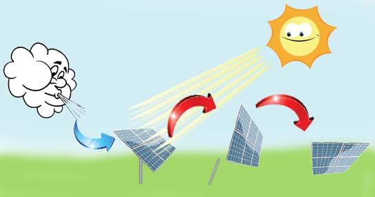
KNOW THE ENVIRONMENT
         Choosing the right solar module support method involves understanding a variety of
environmental factors such as soil conditions, geographic location, and regional wind speeds to name a
few. Other important factors that need to be considered include soil mechanics such as consolidation,
permeability and seepage, bearing capacity, lateral earth pressure, slope stability, as well as wind
engineering to determine potential forces or loads that the solar module installation will be subject to,
based on panel size, panel weight, geographic orientation, etc. Each of these factors needs to be
carefully considered for each and every solar system installation in order to minimize the risk of
downtime caused by damage or failure to the system components and then in turn maximize the ROI or
return on investment of the system.
         With no real “Solar Installation Best Practice Guidelines” available for designers, manufacturers,
or installers to reference or follow, it falls to each individual project personnel to ensure that the proper
environmental and engineering factors are considered during the design, development, and installation
of the solar power system. This results in confusion within the solar industry as to what “minimum
requirements” are and what installation method is best for a given application. Everyday there is a
likelihood that solar modules are being installed somewhere in the US without giving the proper
consideration to the environmental and engineering factors related to the project. This is a failure
waiting to happen. The right rain conditions, the right wind conditions, equal the wrong outcome.
         When employing driven piles, screw augers, or concrete piers, it is essential to consider all of the
environmental factors involved to reduce the risk of “hole widening” or “pole tilting” due to ground
consolidation, “panel rotation” due to wind forces, soil saturation, lateral earth pressure, etc. which can
directly affect the orientation and therefore the efficiency of the panels, and which can also cause
damage to the electrical connections below ground requiring costly repair. When utilizing precast
ballasted footings or ballasted trays it is imperative to understand wind loads, slope stability, soil
permeability and seepage, etc, to know how wind loads can cause overturning or sliding.

                “The Environmental Protection Agency (EPA) is encouraging renewable energy
       development on current and formerly contaminated land and mining sites. The EPA has
       identified thousands of properties that could potentially host solar, wind or biomass
       energy production facilities. The EPA used information on properties from several land
       cleanup programs, including abandoned mine lands and lands under EPA’s Superfund,
       Brownfields, and Resource Conservation and Recovery Act programs.”
                                                       Environmental Protection Agency 2009

                “President Obama and Congress are pushing to identify thousands of
       contaminated landfills and abandoned mines that could be repurposed to house wind
       farms, solar arrays and geothermal power plants.”
                                                       White House 2009

       While the driven pile method was the original preferred method for installing solar modules, the
increasing repurpose of landfills and contaminated superfund sites as home to solar farms has the use of
Precast Concrete Ballasted Footings quickly gaining in popularity. Landfills and contaminated superfund
sites are ideal candidates for solar farms because they are considered already disturbed lands and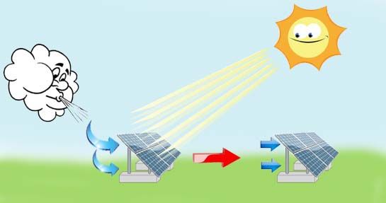
thereby relieve the pressure to develop on undisturbed or uncontaminated lands. However, many of
these sites do not permit or allow ground penetration for obvious reasons. Once you get past the three
feet of top cap soil, you reach the contaminated soil below. This is one area where precast ballasted
footings win out over driven piles because they provide a non penetrating solution. Other areas where
precast ballasted footings are finding success, is in solar installations going in over bedrock where
penetration is difficult if not impossible, solar installations with high water tables, and installations with
adverse soil conditions such as corrosive soils or soils with poor passive earth‐pressure characteristics. In
addition to not penetrating the ground, precast ballasted footings offer a variety of other benefits such
as:
        • No soil Penetration.
        • Minimal site excavation/preparation needed.
        • Speed of delivery and installation
        • Eliminates the need for cast in place concrete and all associated issues including forming,
             pouring, and dry time which can dictate the pace of the installation process.
        • Accommodates most site locations and conditions.
        • Design performance is based on solar asset weight which is known precisely. (on the
             contrary driven piles rely on assumed passive soil pressures and other assumptions)

         If designed, and manufactured properly, precast concrete ballasted footings will outlast the
solar modules they support and should be viewed as a durable asset that in most cases can be
repurposed from one decommissioned solar project to a new solar project. Having a clear understanding
of the environmental and engineering factors involved in a solar project and then manufacturing and
installing the solar power system based on those factors, will greatly increase the efficiency and life
expectancy of the individual components as well as the solar power system as a whole.

POTENTIAL PITFALLS & FAILURES TO CONSIDER
When designing ballasted concrete footings there are 3 stability issues that must be considered:
      • Overturning (up – lift)
      • Sliding
      • Over‐shading

OVERTURNING (UP‐LIFT)
Excessive wind load forces can cause overturning moments (what is commonly referred to as uplift).

Figure 1 – Overturning on Ballasted Footing System          Figure 2 – Overturning on Post Mount System
Overturning on a precast ballasted system, FIGURE 1, results from a failure of the ballasted
footing to successfully counter excessive wind loads. (This means the footing was the wrong weight and
or size for the application.)
         Overturning on a pile driven or post mount system, FIGURE 2, results from a failure of the
mounting hardware, racking system, or post/soil interaction due to excessive wind loads.

HOW TO AVOID OVERTURNING (UP‐LIFT)
          There are two design options to resist the overturning forces (up‐lift) caused by the wind. The
first is simply by adding weight or what is commonly referred to as dead load. This is comprised of the
combined weight of the solar electrical system (panels, racking, connections, etc.) plus the self weight of
the ballasted footing. In addition there needs to be enough dead load to allow for an additional safety
factor that meets or exceeds local building code standards. The second and most important option is
how the dead load is distributed geometrically. Careful thought and rigorous design principles provide
the exact length, width, and thickness of the ballasted footing.
          The orientation of the ballasted footing with respect to the solar electrical system also plays a
key role in determining the size and geometry of the footing, which has a direct impact on overturning
potential. FIGURE 3 illustrates two different ballasted footing layouts for the same solar electrical
system. Although the ballasted footings are the same exact dimensions and weight they behave very
differently due to their orientation.

  Figure 3 – Varying Ballasted Footing Orientation                 Figure 4 – Sliding Of Ballasted Footings

SLIDING
         Sliding is a potential failure that should be considered when designing ballasted footings.
Although not as catastrophic as overturning, sliding can occur due to the wind induced forces on the
solar array system. The wind not only tries to push the Solar Array system horizontally, but it also
creates a lift which reduces the actual dead load of the entire system, see FIGURE 4. This reduced dead
load coupled with the horizontal wind force is what creates the possibility of a solar module and its
foundation sliding horizontally. Taking into consideration the type of Sub grade material on which the
ballasted footings will be installed is the primary factor to provide resistance to sliding. The ideal type of
Subgrade is a well drained granular course material such as sand.

OVER‐SHADING
        Another common mistake is to install rows of solar modules too close together which results in
“over‐shading”. In driven pile or post mount applications this can result from not fully understanding
the affect that a change in height can have on the way shadows fall on the solar system as a whole. With
precast ballasted footings this can occur as a result of altering the thickness of the ballasted footing in an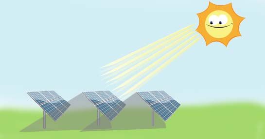
attempt to add weight when additional weight is required due to regions of higher wind speeds. Thicker
ballasted footings could increase the overall height of the solar electrical system which could require an
increase in distance between rows to eliminate possible adjacent‐row over‐shading, see Figures 5 & 6.

Figure 5 – Over‐shading on Ballasted Footing System                Figure 6 – Over‐shading on Post Mount
System

HOW TO AVOID OVER‐SHADING
         Having precise knowledge of the path of the sun as well as a clear understanding of the
significant seasonal 47‐degree solar elevation angle difference above the horizon, and the
sunrise/sunset solar azimuth angle from summer to winter is essential to prevent mistakes when
positioning the solar modules in a solar installation. This will allow the correct height to be calculated for
either a driven pile or ballasted footing installation. When additional weight is required in the design of
a ballasted footing to account for higher winds within a given region, the designer/engineer must take
into account the possibility of adding the weight to the length and or width of the ballasted footing to
prevent an unwanted increase in height.

OTHER FACTORS TO CONSIDER
Bearing Pressures:
Once the footing has been designed (sized) to prevent overturning and sliding failure, the soil bearing
pressures should be checked to ensure that they are in compliance with a soil’s engineer’s report that
may specify maximum bearing pressures.

ENGINEERING AND DESIGN CONSIDERATIONS FOR BALLASTED FOOTINGS
        One of the biggest misconceptions within the solar industry in regards to precast concrete
ballasted footings is that the footing size and the unit cost are directly related to the energy output or
watts of the solar electrical system. This could not be farther from the truth. The footing designs have
nothing to do with the power output or price per watt, and everything to do with the following:
        • Tilt angle and tracking characteristics of the solar power system.
        • Local design wind speeds where the solar power system is to be installed.
        • Support and racking configuration.
        • Overall solar module system size and weight.
        • Local design codes and project requirements.
        • Soil characteristics relative to friction, sliding, consolidation, slope stability, etc.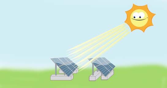
Tilt Angle:
        To maximize the output of the solar power system, especially in PV Solar Array applications, the
optimal tilt angle is typically specified for non‐tracking systems, and remains fixed.
Structurally, higher tilt angles result in an increased wind load on the solar module which would require
a larger ballasted footing. In addition, higher tilt angles may require an increase in distance between
rows to eliminate adjacent‐row over‐shading, see FIGURE 5.            A lower tilt angle is often desired to
minimize the wind forces and reduce the ballasted footing size. This may not be feasible in areas of
substantial snowfall where an increased tilt angle may be required to shed snow off of the solar module
effectively. A lower tilt angle also results in reduced adjacent‐row over‐shading potential which allows
the module rows to be spaced closer together. A cost comparison could be done to compare the tilt
angle versus the adjacent‐row over‐shading versus the ballasted footing size. In addition, lower tilt
angles allow for more compact utilization of the land available by minimizing the unusable area that is in
shade thus offering an opportunity for more solar modules.

Wind Speed:
        The most significant impact on the ballasted footing design is due to the local design wind
speed. The local design wind speed can be found from the International Building Code, IBC, or from
the local building department where the solar power system is to be installed. It is imperative to get
the correct design wind speed as it has a direct impact on the footing dimensions, and thereby the
economics of the project. The force on the solar power system from the wind is directly related to the
                       2
wind speed squared, V .

Design Codes:
        Currently there are no design specifications or prescribed methodology that applies to the
design of foundations for solar power systems. Depending on which engineer you ask, you will get a
different answer based on the engineer’s academic background and experience, or lack thereof. The
main problem facing design engineers of solar power systems is how wind loads factor into the function
and performance of the components. The ACSE wind code is the most applicable and industry‐approved
standard. The challenge is identifying and interpreting the right part of the code, and then applying it to
solar power systems.

CONCLUSION
         At Oldcastle Precast, reliability is the cornerstone of everything we do and it is what
thousands of satisfied customers have come to expect. We have the equipment and the expertise to
handle even the most challenging jobs, from concept to install and every step in between. We
consider ourselves the leader in the market place with regards to delivering a fully engineered system to
accommodate any solar power configuration and meet the needs of the end user.
         The leadership of Oldcastle Precast has completed an R&D initiative related to the design of
risk‐mitigated solar foundation products. This project has culminated in the development of proprietary
software that allows us to provide our customers with products that have been engineered to perform
at the highest levels in the industry.
         Oldcastle Precast will assist in smart designs making installation and fabrication at the job site
easier and faster. We will provide you with an installation manual and be at the job site on day one to
insure a successful project. We have a team devoted to supplying you with a wide range of services and
products.
         At Oldcastle Precast we are committed to delivering the reliability that has made us the
Industry Leader.
Source Information
The Environmental Protection Agency (EPA)2009
“The Environmental Protection Agency (EPA) is encouraging renewable energy development on current and formerly
contaminated land and mining sites. The EPA has identified thousands of properties that could potentially host solar, wind or
biomass energy production facilities. The EPA used information on properties from several land cleanup programs, including
abandoned mine lands and lands under EPA’s Superfund, Brownfields, and Resource Conservation and Recovery Act programs.”
http://www.epa.gov/renewableenergyland/
White House 009 Environmental Statement
President Obama and Congress are pushing to identify thousands of contaminated landfills and abandoned mines that could be repurposed to
house wind farms, solar arrays and geothermal power plants.”
http://wwwp.dailyclimate.org/tdc‐newsroom/2009/10/green‐shoots‐from‐brownfields
Larry J. Miller, P.E. | Jackson Bishop | Oldcastle Precast, Inc., 7921 South Park Plaza, Suite 200, Littleton, CO | 888‐965‐3227 |
www.Oldcastleprecast.com/energy
October 2009 V1You can also read