A review of "performance analysis and optimization of car air spoilers" - IOPscience
←
→
Page content transcription
If your browser does not render page correctly, please read the page content below

IOP Conference Series: Materials Science and Engineering

PAPER • OPEN ACCESS

A review of “performance analysis and optimization of car air spoilers”
To cite this article: K K Singh et al 2019 IOP Conf. Ser.: Mater. Sci. Eng. 691 012056

View the article online for updates and enhancements.

                                This content was downloaded from IP address 46.4.80.155 on 31/05/2021 at 11:18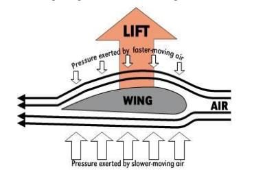
ICCEMME 2019                                                                               IOP Publishing
IOP Conf. Series: Materials Science and Engineering 691 (2019) 012056 doi:10.1088/1757-899X/691/1/012056

A review of “performance analysis and optimization of car air
spoilers’’
                     K K Singh1,*, H Bahri2, H Singh3 and J Singh4
                     1
                      G L Bajaj Institute Of Technology and Management, Greater Noida, India
                     2
                      G L Bajaj Institute Of Technology and Management, Greater Noida, India
                     3
                      G L Bajaj Institute Of Technology and Management, Greater Noida, India
                     4
                      G L Bajaj Institute Of Technology and Management, Greater Noida, India

                     * Corresponding author. Tel: +917599365971, E-mail: kshlndra03@gmail.com

                     Abstract. Before last decade, due to surplus amount of fuel, cars are designed for high speed
                     operation, comfort and safety. As scarcity of fuel increases due to high consumption of fuel in
                     automobiles, many researchers started working on the idea of alternative fuels, redesign of car
                     body and reducing aerodynamic losses. To overcome these losses spoilers are used and hence it is
                     needed to optimize its shape. This study is primarily focused to find out optimized shape of car
                     spoiler so that mass can be minimized which help in reducing fuel consumption without affecting
                     its aerodynamic properties and strength. Computational Fluid Dynamics (CFD) analysis of two
                     dimensional model of spoiler is done whose results are validated by earlier research work in this
                     field for understanding variation of aerodynamic property of cross-section. Three dimensional
                     CFD analysis of spoiler gives aerodynamic property and pressure data which is needed to compare
                     result of optimized model formed by optimized cross-sectional shape. Shape optimization is done
                     by Shape Optimization tool of ANSYS 14.0 which is further tested for design failure in ABAQUS
                     6.11. The result of shape optimization has saved 18.74% of material keeping all its strength and
                     aerodynamic property intact. This study open provides a numerical tool for improvement of future
                     model of spoiler in terms of reduction of mass.

Keywords: Car Air spoiler, Coefficient of lift, Coefficient of drag, Shape optimization, Stress analysis.

1. Introduction
In early nineties there was ample amount of fuel oil was available in market, but as there is scarcity of
fuel oil started, there is a hike in fuel prices. Earlier main aim of car’s design was high-speed operation,
comfort and safety only. As hike in fuel was there many people started thinking on various aspects to
overcome this problem and increase sale of automobile industry. Besides the idea of alternative fuel,
losses due to aerodynamics are also main concern of many researchers. In India due to strengthen
economy sales of transportation vehicle especially cars has increased a lot since 2000.
This study is focused on optimizing shape in such a way, that mass is reduced keeping all its strength,
coefficient of drag (CD) and coefficient of lift (CL) same. Fuel saving potential of drag reducing devices,
which can be fitted on heavy vehicle is studied by a numerical study and found that these devices reduce
fuel consumption up to 9%. The annual saving of fuel ranges from 600 to 2600L [1].
Shape optimization considers all constraints on geometry, stress, displacement etc. Under all these
constraints it will provide a new optimized shape to two dimensional (2D) or three dimensional (3D)

              Content from this work may be used under the terms of the Creative Commons Attribution 3.0 licence. Any further distribution
              of this work must maintain attribution to the author(s) and the title of the work, journal citation and DOI.
Published under licence by IOP Publishing Ltd                          1
ICCEMME 2019 IOP Publishing
IOP Conf. Series: Materials Science and Engineering 691 (2019) 012056 doi:10.1088/1757-899X/691/1/012056
components with minimum mass or weight. In emerging world of faster computers, powerful structural
analysis and optimization can be done to improve design in an efficient manner. It is suggested to pay
attention on shape optimization algorithms which can solve mechanical design problem in a better
suitable way [2].
The major problem of drag reduction in car is keen topic since last decade and hence comes in picture
computational cost and its complexity. Drag minimization of 3D car model using concept of
Computational Fluid Dynamics (CFD) is validated through experiments so that it can be used for further
design modifications [3].
Spoiler are analyzed on the basis of aerodynamics properties and earlier not very much work is done
in field of shape optimization of spoilers using Finite Element Method (FEM) techniques and Shape
Optimization tool of ANSYS 14.0 to reduce the mass and fuel consumption.
1.1 Spoilers Aerodynamics
Spoilers are aerodynamic device used in automobiles and faster moving cars to remove turbulence across
body of car. It is attached to an automobile. One of the problems for vehicles is to control wake.
Suggested method is to change rear body shape and change of shape of spoiler and result of experiments
is a great reduction in value of CD and CL [4] Reduction is shown in ‘figure 1.1’
Figure 1.1. Result of pre-tests for new shape(Fukuda, et al. 1995)4
1.2 Function of Spoilers
Spoilers help to reduce form drag and aerodynamic noise both at same time. In addition, it also reduces
lift and improves traction leading to better maneuver [5].This study defines that intended function of this
device is to spoil unfavorable air movement across body of vehicle of some kind in motion. The main
function of a spoiler is diffusing airflow passing over and around a moving vehicle as it passes over
vehicle. This diffusion is accomplished by increasing amounts of turbulence flowing over shape,
“spoiling” the laminar flow and providing a cushion for the laminar boundary layer.
2ICCEMME 2019 IOP Publishing
IOP Conf. Series: Materials Science and Engineering 691 (2019) 012056 doi:10.1088/1757-899X/691/1/012056
1.3 Working of Spoilers
Spoilers working can be understood by help of concept of uplift of airplane wing. As shown in ‘figure
1.2’ air moving bottom to wing will travel shorter distance as compared to air moving on top surface of
wing which creates a pressure difference and creates an uplift of wing.
Figure 1.2. Airflow around airplane wing.
A car experiences various types of lift, drag and down force due to its shape. These forces are
shown in ‘figure 1.3(a)’. So when down force is needed inverted wing is used as in case of spoilers.
Spoiler helps to turn upper airstream in direction as shown in ‘figure 1.3(b)’, so that airstream causes
down forces at rear end. In this way spoiler reduces uplift at high speed.
(a)
(b)
Figure 1.3 (a) Airflow around car without spoiler
(b) Airflow around car with spoiler
3ICCEMME 2019 IOP Publishing
IOP Conf. Series: Materials Science and Engineering 691 (2019) 012056 doi:10.1088/1757-899X/691/1/012056
2. Material Analysis
Yet again fuel consumption is studied and tried to be reduced by changing conventional material to
advanced material. These reforms must be taken care to meet high future demand specifications. In this
context suggested material for spoilers is unreinforced thermoplastic [6]. The most common material in
this class is Acrylonitrile Butadiene Styrene (ABS) plastic. For better strength and stress absorption
capacity fabrication to be done using sandwich construction in which ±45 o orientation of fibers with foam
gives better result than ±45o orientation of fibers without foam [7]. Another recent material suitable for
spoilers is soft morphed materials. soft morphing structures are capable of continuous curvilinear
structural deformation upon actuation without discrete sections that generate aerodynamic losses [24].
fabricated a woven type smart soft composite consisting of shape memory alloy wires and glass fiber-
reinforced composite and applied to the rear spoiler. To verify its aerodynamic performance, wind tunnel
experiments were carried out using a stand-alone spoiler under various wind speeds, angles of attack then
the spoiler was mounted on the small-scale car and wind tunnel tests were conducted to determine the
potential of augmentation on aerodynamic performance by implementing the soft morphing spoiler.
3. Design Analysis
Comparison of various aspects (likes shape, material) in designing Human Powered Vehicles on various
road conditions is studied and found that magnitude of drag depends on physical appearance such that
body shape, accessories attached ,extrusions etc.[8]. A comparative analysis of lift and drag on sedans
with and without back spoilers and the hatchbacks with and without front spoilers was performed. The
study was based on three turbulence models which showed that the drag marginally increases and the lift
decreases by using the spoilers. The decrease in lift increases the down force and this overcomes the
effect of increase in drag [19].The aerodynamic impacts on sedan car’s fuel economy due to different
spoilers mounted on different locations on the car back side was presented. They performed the CFD
analysis of 3D computer model of 4- door sedan cars which was created on solid works and presented the
coefficient of lift and drag values for each of the spoiler combinations [22].
For smooth flow around spoiler six basic shapes of rear spoiler have been studied and numerical
simulation is performed for analysis of stability and noise produced. This analysis suggest that among six
shapes case 4, which is an aerofoil shape, has made flow smooth with lower noise level and proposed for
spoiler shape ‘figure 2’. In fact it smoothens flow and reduces turbulence at tail [12].Two spoiler models,
NACA 4412 and NACA 6409 were incorporated on a car rare side and tested to obtained the lift and drag
forces for each spoiler model. The models were created on 3D software CREO and analysis was
performed on CFD workspace at different air speed to investigate the performance parameters [21].
Figure 2. Configuration of spoilers.
4ICCEMME 2019 IOP Publishing
IOP Conf. Series: Materials Science and Engineering 691 (2019) 012056 doi:10.1088/1757-899X/691/1/012056
4. CFD Analysis
As CFD tool is an important tool in analyzing fluid behavior. Many studies have been performed in order
to get best results and validation. Modelling car geometry and analyzing for CFD gives results like
experiments and behavior is predicted in advance and effect of applying spoiler on rear part of car is
studied by making a basic car model and running CFD simulation to find C D and CL values first without
spoiler and then with spoiler and found percentage reduction in CD and CL value be 1.7 and 4 respectively
[9]. A similar study has been performed later with different model of car and found drag was reduced by
2.02% while lift reduction was exceptional 14.06% [10]. Analysis of wake flow-field, downstream of a
square back car model to investigate the combined effect of horizontal and vertical deflectors was
presented. They found that vertical deflector’s height was playing a key role in this scenario markedly
affecting the resulting drag and lift coefficients. Analysis of velocity fields pointed out the existence of an
optimal vertical spoiler size, in the presented set-up equal to 2/3 of model height, which featured the
overall best performance compared to other tested configurations. The beneficial effect of combined
spoilers was found to be more relevant when horizontal and vertical deflectors feature a moderate (20°)
slant angle with respect to free stream direction [16]. Comparison of large eddy simulations (LES) and the
wall modelled large eddy simulations (WMLES) was done on the flow over a realistic generic car
geometry and a 70% CPU time reduction was obtained using the WMLES [18]. A RANS – based CFD
analysis was performed to find the impact of different spoiler angles on the lift and drag forces of
hatchback vehicles. The numerical results showed that at positive spoiler angle, the aerodynamic lift of
the hatchback model reduced up to 2937% however the spoiler effect was unfavorable to lift reduction
when configured at negative inclination angle. Although the lift was found to decrease with increase in
spoiler angle [20].
5. Shape Optimization
(Hsu 1994) Shape optimization is defined as a set of geometrical modelling, structural analysis and
optimization. In primary step of making design model, geometrical representation of boundary shapes and
design variable are defined. The design optimization problem thus can be written as:
Minimize f(x)
Subject to g1(x) ≤ 0
g2(x) ≤ 0
where x is vector of design variable, f(x) is objective functions, g1(x) ≤ 0 and g2(x) ≤ 0 are constraints.
Further analysis model is created separately by help of design model. Choice of analysis technique
depends upon converting design model into analysis model, capability and accuracy of analysis
technique. In next steps optimization algorithm is used to optimize component. The flowchart for shape
optimization process is shown in ‘figure 3’. Multi objective optimization using FEA and Multi Objective
Genetic Algorithm (MOGA) are solved to find all Pareto’s optimal solutions in one go. Earlier multi
objective optimization is solved by transforming function into single objective function. It is found that
MOGA is better alternative for multi objective optimization of auto panel drawing die face design [12].
ANSYS’s Shape Optimization tool has been used to reduce weight as well as cost of steel connecting rod.
They used weight and cost as their objective function keeping geometry and manufacturing cost as design
variable and constraint respectively. They found that using ANSYS easily it can optimize shape of
component which in their case is 10% and 20% weight reduction keeping cost in direct relation to weight
[10].
5ICCEMME 2019 IOP Publishing
IOP Conf. Series: Materials Science and Engineering 691 (2019) 012056 doi:10.1088/1757-899X/691/1/012056
Figure 3. Process of shape optimization,
6. Conclusions
An ample amount of work on car air spoilers has been done but most of the researches emphasizes on
reduction of coefficient of drag (CD) and coefficient of lift (CL) by the relative wind. But the modern
researchers like [12] and [10] have done very well in the field of optimization with the help of which the
mass of spoilers can be reduced for a given spoiler keeping its coefficient and coefficient of drag the
same. After reviewing a plenty number of research papers, we have reached on following conclusions.
1. k-ε turbulence model is used for CFD calculation which provides value of CD and CL at
different angles of attack both for 2D and 3D analysis which gives idea of accuracy of model and
reliability of software package.
2. FEA can be done with the help of pressure variation around spoiler which is found in 3D
analysis and can suggest that model is having what amount of maximum stress which is
equivalent to a safe design having some desired factor safety.
3. Shape optimization tool of ANSYS 14.0 is very useful and easy to understand which provides
the shape of spoiler with a reduced mass keeping all CD and CL values almost same but it gives
some maximum stress. The most common material for the fabrication of spoilers is ABS plastic,
because of its better strength and the stress absorption capacity. And a good amount of mass can
be reduced by making section of spoiler hollow. However doing so increases maximum stress but
it is not leading system failure.
7. References
[1] Mohamed K, Zulfaa and Antonio F 2010 Transportation Research Part D 15, 5 275-284.
[2] Hsu and Liang Y 1994 Computer in Industry 25, 1 3-13.
[3] Dumas and Laurent 2008 Optimization and Computational Fluid Dynamics Laurent Dumas,.
Berlin Heidelberg Springe 1 191-215.
6ICCEMME 2019 IOP Publishing
IOP Conf. Series: Materials Science and Engineering 691 (2019) 012056 doi:10.1088/1757-899X/691/1/012056
[4] Fukuda H, Kazuo Y, Hiroshi C and Kunio N 1995 JSAE Review 16, 2 151-55.
[5] Sunanda A, and Siva Nayak M 2013 International Journal of Emerging Technology and Advanced
Engineering 3 1 236-242.
[6] Jambor, Arno, and Matthias B 1997 Materials & Design 18, 4 203-9.
[7] Chodagudi, Kamprasad, and Rao T B S 2012 International Journal of Engineering Research &
Technology 1 7 1-5.
[8] Alam, Firoz, Harun C, Erika G, Jie Y, and Gary Z 2013 Procedia Engineering 60 473-478.
[9] Hu, Xu X and Eric T T W 2011 World Academy of Science, Engineering and Technology 57 636-
41.
[10] Ramani H B and Kumar N 2013 International Journal of Engineering Research & Technology 2 2
1-5.
[11] Liu, Wei, and Yuying Y 2007 Computer-Aided Design 39 10 863-869.
[12] Tsai, Chien H, Lung M F, Chang H T, Yen L H and Jik C L 2009 Applied Mathematical
Modelling 33 9 3661–3673.
[13] Yeung and William W H 1985 The University of British Columbia 5 43-48
[14] Pundir B P 2008 Fuel Economy of Indian Passenger Vehicles - Status of Technology and Potential
FE Improvements Pundir B P Kanpur Indian Institute of Technology Kanpur 4 155-60
[15] Sharma R B and Bansal R 2013 International Journal of Automobile Engineering 3 13-22.
[16] Min W H, Hugo R, Seunghyun C S H S, Wei W, Won-Shik C S H A 2016 Woven type smart soft
composite for soft morphing car spoiler, 86 295-298.
[17] Alessandro C and Giovanni P R 2019 Journal of Wind Engineering and Industrial Aerodynamics
185 57-64.
[18] AljureJ D E, Calafell A, Baez A O 2018 Journal of Wind Engineering and Industrial
Aerodynamics 174 225-240.
[19] Vivek Y, Shankar M 2018 Car International journal of scientific research and review 7 271- 280.
[20] Cheng S Y, Shuhaimi M and Azman A 2017 International Journal of Applied Engineering
Research 12 12927-33.
[21] Dr Kumar M V S, Rao B A and Dr Mallaiah G 2017 International advanced research journal in
science engineering and technology, 4 256-261.
[22] Ganesh G, Vasudevan V 2015 International Journal of Scientific & Engineering Research, 6 762-
6.
7You can also read