ANALYSIS OF ALLOY WHEEL RIM STYLING STRUCTURE USING ALUMINIUM AND MAGNESIUM ALLOYS - IRJET
←
→
Page content transcription
If your browser does not render page correctly, please read the page content below
International Research Journal of Engineering and Technology (IRJET)                                          e-ISSN: 2395-0056
        Volume: 07 Issue: 08 | Aug 2020                    www.irjet.net                                              p-ISSN: 2395-0072

         ANALYSIS OF ALLOY WHEEL RIM STYLING STRUCTURE USING
                   ALUMINIUM AND MAGNESIUM ALLOYS
                                           P Santosh Reddy1 and Dr. R Ramesh2
                              1PG   Scholar, MVGR College of Engineering, Vizianagaram, India.
                   2Professor,    Department of ME, MVGR College of Engineering, Vizianagaram, India.
---------------------------------------------------------------------***---------------------------------------------------------------------
Abstract - The wheel rim designed must be durable enough                 there is no common solution to say which material is the
to withstand rough loads, harsh environments and must meet               best for the automobile wheel rim. Though it is due to
both the styling appearance and engineering functions. The               changes in design structures, manufacturing ease but the
present work gives a brief compilation of research related to            main reason is due to volatility in tests. Alloy wheels for use
analysis of equivalent maximum stresses in passenger car                 on passenger cars has to pass three tests namely Dynamic
wheel rim by operating various loading conditions like radial,           Cornering Fatigue Test, Dynamic Radial Fatigue Test and
bending and impact loads. The design and analysis of the                 Impact Test before going into the production [4]. The
wheel rim is done based on Design for Manufacturing                      different types of alloy wheels are,
methodology. A new CAD model of the wheel rim is prepared                Steel Alloy: It has an excellent feature of high fatigue
for the passenger car wheel rim of 17 inch diameter according            strength, and can withstand maximum number of cyclic
to TRA standards in CATIA V5. The 3D model of the wheel rim              loads. But the main reason for not using this alloy wheel is
is imported to NX Nastran for analysis and for solving, finite           due to its heavy weight, fuel consumption is more.
element technique is used. The analysis is done by simulating
the model, using Static structural analysis on aluminium and             Aluminium Alloy: It has features of excellent lightness,
magnesium alloy materials respectively. Finally relative                 thermal conductivity, physical characteristics of casting, low
performance characteristics are reported, based on maximum               heat, machine processing and re-utilization etc,. This alloy
equivalent stresses and the optimal material for usage is                wheel is mostly used due to its main advantages of
selected for the wheel rim, in order to increase the fatigue             decreased weight, high precision and design choices of the
strength and service life along with optimal fuel consumption            wheel.
for the vehicle.                                                         Magnesium Alloy: It has all the features similar to
Key Words: Alloy Wheel, NX Nastran, Static Structural                    aluminium alloy and additionally, it has superior size
Analysis, Cornering Fatigue Test, Radial Fatigue Test, Wheel             stability and impact resistance, but is somewhat costlier than
Impact Test, Design for Manufacturing.                                   aluminium alloy. However, its use is mainly restricted to
                                                                         racing, which needs the features of weightlessness and high
1. INTRODUCTION                                                          strength.
                                                                         Titanium alloy: It is an admirable metal for corrosion
    An automobile is a combination of various parts like
                                                                         resistance and the strength is about 2.5 times more
engine, transmission, body, suspension system, wheels etc,.
                                                                         compared to aluminium alloy. But the main reason for not
Wheels are critical components and are of primary
                                                                         using this alloy is due to its inferior machine processing,
importance for human safety. Wheel is generally composed
                                                                         designing and more costlier.
of rim and tire assembly. Alloy wheels are wheels which are
mostly made of aluminium or magnesium alloys. Though                     Composite material: It is different from other alloy wheels,
other materials like composites, titanium and steel alloys               it is developed mainly for low weight. But the main reason
come under this category. The alloy wheel is prominently                 for not using this type of wheel is due to its inadequate
used due to its lighter in weight, more strength, excellent              consistency against heat, best strength and lack of
corrosive resistance, better heat dissipation and stylish                knowledge related to processing and recycling method to be
appearance. Mostly, the alloy wheels are manufactured by                 used.
low pressure die casting process.
                                                                         2. MATERIALS AND METHODS
    In general, design of the wheel is done by first modelling
the wheel rim and then subjected to various structural                   2.1 Aluminium alloy
analysis. The modelling and analysis is done by using various
reliable software which had an ease in solving the                           Aluminium is a chemical element with the symbol ‘Al’.
component. Finite element methods are mostly used to                     Aluminium is the ideal light-weight material as it allows
evaluate the performance of the wheel rim. Based on the                  mass saving of up to 50% over competing materials in most
studies on material selection of wheel rim, it is observed that          applications without compromising safety. [5]. Aluminium
the materials that are mostly used are alloys of steel,                  alloys are either cast or wrought alloys and can be
aluminium, magnesium titanium and composites [1,2,3]. But                categorized into a number of groups based on particular

© 2020, IRJET          |    Impact Factor value: 7.529               |    ISO 9001:2008 Certified Journal                 |    Page 4483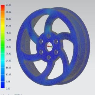
International Research Journal of Engineering and Technology (IRJET) e-ISSN: 2395-0056
Volume: 07 Issue: 08 | Aug 2020 www.irjet.net p-ISSN: 2395-0072
materials' characteristics, such as its ability to respond to deign of wheel rim there are three phases used. The phases
thermal and mechanical treatment and the primary alloying in DFM for the wheel rim are listed below.
element added to the aluminium alloy.
Design for Form: The shape, size, dimensions or other
A356-T6 aluminium alloy: The primary alloying element is parameters which characterize the physical look of the item.
silicon plus copper and/or magnesium. Alloy A356 has
No sharp edges, that is the edges are removed by
greater elongation, higher strength and considerably higher
applying fillet at the corners.
ductility than alloy 356 because of low iron content in it. This
A356 aluminum casting alloy has good cast-ability, this Wheel rim profile drawn following the standards (TRA,
makes it a logical choice for intricate and complex castings. ETRTO, JIS), in the present study the TRA(Tire and Rim
Association) standards are being used.
The advantages of using aluminium alloy A356 are
mainly due to its properties of, strength to weight ratio, A minimum of 7° draft angle is to be maintained for
ductility and durability, hardness, fatigue strength, pressure casting ease.
tightness, corrosion resistance, easy to machine, recycle and
Thickness of spoke should be more than 12mm.
re-usability.
Design for Fit: The parameters and ability which make it
2.2 Magnesium alloys appropriate for integration with other components within an
assembly including its tolerances.
Magnesium is a chemical element with the symbol ‘Mg’.
Magnesium alloys significantly contribute to greater fuel Wheel fitment with the tire.
economy and environmental conservation. Magnesium alloy
Providing fitment for brake calliper
results in a 22 to 70% weight reduction in compared to
alternative materials [6]. The physical properties of the Required hole for mounting flange to fit.
alloys change based on their chemical compositions.
Provision for wheel balancing (sticking, clip set)
Magnesium alloys are defined based on codes in ASTM
(American Society for Testing and Materials). Spacing's in the wheel rim for wrenches, bolts, nuts etc,.
AZ91 Magnesium alloy: The primary alloying elements is of Design for Function: The operation of the item or the
aluminium (9%) and zinc (1%). AZ91 dominates as a actions it is intended to perform.
production route of magnesium alloy and large number of
Cornering fatigue test (CFT).
parts are cast due to its high productivity, high precision and
high quality surface. In this AZ91, aluminium improves Radial fatigue test (RFT).
strength, hardness and ductility, facilitating the alloy’s
Wheel Impact test (13°).
casting process while zinc increases room-temperature
strength, fluidity in casting, and corrosion resistance. Cornering Fatigue Test: The cornering fatigue test is one of
the traditional durability tests of prototype verification. The
The advantages of using AZ91 magnesium alloy are
test procedure for cornering fatigue performed in
mainly due to its properties of, strength to weight ratio,
accordance with SAE (Society of Automotive Engineers)
damping capacity, dimensional stability, electromagnetic
standards. The dynamic CFT simulates the loading condition
shielding, anti-galling, corrosion resistance, recycle and re-
of wheel in normal driving mode, the test machine shall have
usability.
a driven rotatable device whereby wheel rotates under the
Table-1: Material properties of Al and Mg alloys influence of stationary bending moment and is subjected to
rotating bending moments [7].
S.No Material Property A356 AZ91
Radial Fatigue Test: The radial fatigue test is one of the
1 Elastic Modulus (GPa) 72 45
traditional durability tests of prototype verification. Wheel
2 Density (kg/m3) 2670 1800 radial fatigue tests were performed in accordance with SAE
(Society of Automotive Engineers) standards. The dynamic
3 Poisson ratio 0.33 0.35 RFT is equipped with a driven rotatable drum parallel to the
4 Yield Strength (MPa) 186 169 axis of test wheel, this load constantly compresses the wheel
radially [8].
5 Ultimate Tensile Strength(MPa) 262 240
Wheel Impact Test: The wheel impact test establishes
minimum performance requirements and evaluates axial
2.3 Methodology: Design for Manufacturing (DFM) (lateral) curb impact collision properties of all wheels
intended for use on passenger cars. The Impact Loading
Design for Manufacturing is an engineering practice of Machine and the wheel hub mount are designed as per the
designing products in such a way that, they are easy to SAE (Society of Automotive Engineers) specifications. The
manufacture, reduce manufacturing costs, potential wheel tire assembly is mounted at an angle of 130 to the
problems fixed in design phase. In the present work, for
© 2020, IRJET | Impact Factor value: 7.529 | ISO 9001:2008 Certified Journal | Page 4484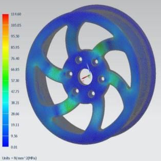
International Research Journal of Engineering and Technology (IRJET) e-ISSN: 2395-0056
Volume: 07 Issue: 08 | Aug 2020 www.irjet.net p-ISSN: 2395-0072
horizontal plane, so that the striker impacts the outer bead 3.2 Analysis of Wheel Rim
radius at the rim near the air valve hole. [9].
Analysis of the wheel rim is done by, simulating the
3. RESULTS AND DISCUSSION designed wheel rim based on static structural analysis using
3.1 Design of Wheel Rim finite element analysis technique to validate the results in NX
Nastran software.
The CAD model of the wheel rim is prepared for the The analysis of the wheel rim is done following the these
passenger car wheel. For a passenger car wheel rim, 17 inch steps mentioned below,
diameter rim, 7.5 inch rim width, J type of flange and the rim
of 50 drop centre rim contours are taken as specified in the 1) Pre-processing: It is the initial stage of simulation which
TRA. Iterations are made for the spoke profile by roughly include checking the geometry, assigning material, meshing
drawing the spoke pattern and changing the number of the model and applying boundary conditions.
spokes. By taking rim diameter and rim width the offset, 2) Processing: It is simply the solution finding stage, here
centre bore and bolt pattern can be chosen based on DFM in the different structural analysis (CFT, RFT, Wheel Impact
CATIA V5. test) are performed by applying the different loads on the
Table-2: Specifications of Wheel Rim model.
S.No Wheel Specification Value 3) Post-processing: This is the final stage of simulation
1 Rim Diameter 17 inch where the results are obtained for the model. Based on the
results critical stress points are noted down and finally
2 Rim Width 7.5 inch
validate the model.
3 Offset 45 mm
4 Pitch Circle Diameter 120 (16*6) mm Simulation for Cornering Fatigue Test
5 Centre Bore Diameter 60 mm
The 3D model of the wheel rim along with a shaft is
6 No. of Spokes 6
imported to NX Nastran, and for solving FEM is used. The
Wheel rim and shaft assembly is made properly with the
The different steps that followed for a new wheel rim design materials selected for wheel rim as Aluminium alloy/
are as follows, Magnesium alloy and for shaft as Structural steel.
1. Drawing rim profile
2. Drawing spoke profile
3. Drawing lug nut hole
4. Drawing mounting flange hole
5. Edge Filling
6. Review the Wheel Rim design
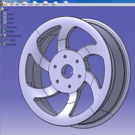
During this design of styling concept of the wheel rim, a
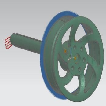
great importance is given while drawing the chamfer edges, Figure-2 : a) CFT meshed model, b) CFT meshed model
draft angles and fillet radius to minimize stresses due to with loading & boundary conditions
fatigue loading for satisfying the design for form, in addition
The model is meshed by using a tetrahedral mesh of type
the lug nut holes, mounting flange holes are drawn for
CTETRA 10, as shown in fig-2(a). By making use of mesh
satisfying the design for fit. The final view of the wheel rim
command the size of the mesh is controlled. The inner flange
design in CATIA V5 is shown in fig-1. Finally the design is
surface is constrained in all six degrees of freedom. A vertical
saved in IGES file format.
load of 3882 N on the free end of the shaft is applied, as
shown in fig-2(b). Finally for each component, assigned
material specifications, boundary conditions, load applied,
3D mesh geometry are checked properly according to the
cornering fatigue test simulation procedure, and run the
analysis.
Simulation for Radial Fatigue Test
The 3D model of the wheel rim along with a tire and slab
is imported to NX Nastran, and for solving FEM is used. The
Wheel rim, tire and slab assembly is made properly with the
materials selected for wheel rim as Aluminium alloy/
Figure-1: Final 3 D view of wheel Rim
© 2020, IRJET | Impact Factor value: 7.529 | ISO 9001:2008 Certified Journal | Page 4485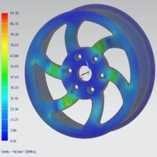
International Research Journal of Engineering and Technology (IRJET) e-ISSN: 2395-0056
Volume: 07 Issue: 08 | Aug 2020 www.irjet.net p-ISSN: 2395-0072
Magnesium alloy, slab as structural steel, and for tire as 3.3 Test results under Cornering Fatigue Test
polyethylene.
For the cornering bending load of 3882 N is applied on
the free end of the shaft, the maximum equivalent stress
value obtained for aluminium alloy of grade A356-T6 is
94.20 N/mm2, as shown in fig-5(a) and magnesium alloy of
grade AZ91 is 114.60 N/mm2, as shown in fig-5(b). The
maximum stress value is obtained at the hub and spoke
joining area on the front face of the wheel.
Figure-3 : a) RFT meshed model, b) RFT meshed model
with loading & boundary conditions
The model is meshed by using a tetrahedral mesh of type
CTETRA 10, as shown in fig-3(a). By making use of mesh
command the size of the mesh is controlled. The lug holes
and mounting flange surface is constrained in all six degrees
of freedom. A radial load of 17805 N on the slab towards the
wheel rim and tire is applied, as shown in fig-3(b). Finally for Figure-5 : a) Al wheel rim results under CFT, b) Mg wheel
each component, assigned material specifications, boundary rim results under CFT
conditions, load applied, 3D mesh geometry are checked 3.4 Test results under Radial Fatigue Test
properly according to radial fatigue test simulation
procedure, and run the analysis. For the radial load of 17805N applied on the slab
Simulation for Wheel Impact Test towards the wheel rim and tire, the maximum equivalent
stress value obtained for aluminium alloy of grade A356-T6
The 3D model of the wheel rim along with a slab is is 73.00 N/mm2, as shown in fig-6(a) and magnesium alloy of
imported to NX Nastran and for solving FEM is used. The grade AZ91 is 92.80 N/mm2, as shown in fig-6(b). The
Wheel rim and slab assembly is made properly with the maximum stress value is obtained at the ends of the spoke
materials selected for slab as structural and wheel rim as connecting to mounting face.
Aluminium alloy/ Magnesium alloy.
Figure-6 : a) Al wheel rim results under RFT, b) Mg wheel
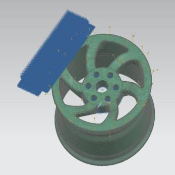
Figure-4 : a) Impact test meshed model, b) Impact test rim results under RFT
meshed model with loading & boundary conditions
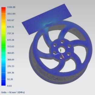
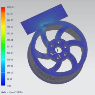
3.5 Test results under Wheel Impact Test
The model is meshed by using a tetrahedral mesh of type
CTETRA 10, as shown in fig-2(a). By making use of mesh For the impact load of 6033N applied on the slab at an
command the size of the mesh is controlled. The lug holes incline of 13° to horizontal direction, the maximum
and mounting flange surface is constrained in all degrees of equivalent stress value obtained for aluminium alloy is
freedom. An impact load of 6033 N on the slab at an incline 1009.02 N/mm2 and magnesium alloy is 1106.00 N/mm2
of 13° to horizontal direction is applied, as shown in fig-4(b). respectively. The maximum stress value is obtained at the
Finally for each component, assigned material specifications, flange part on the front surface of the wheel rim. The
boundary conditions, load applied, 3D mesh geometry are maximum stress obtained under wheel impact test is not
checked properly according to the wheel impact test considered, as we don’t consider the hit area of the wheel
procedure, and run the analysis. rim, as this is a sudden load applied. The maximum stress
obtained nearby bolt hole on the front surface of the wheel
rim is 504.53 N/mm2 for aluminium alloy of grade A356-T6,
© 2020, IRJET | Impact Factor value: 7.529 | ISO 9001:2008 Certified Journal | Page 4486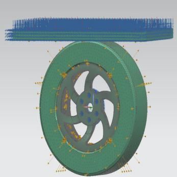
International Research Journal of Engineering and Technology (IRJET)                                    e-ISSN: 2395-0056
        Volume: 07 Issue: 08 | Aug 2020              www.irjet.net                                              p-ISSN: 2395-0072

as shown in fig-7(a) and 553.02 N/mm2 for magnesium of              REFERENCES
grade AZ91 alloy, as shown in fig-7(b) respectively.
                                                                    [1]    K.N.D. Malleswara Rao et.al, “Model optimization and
                                                                           structural analysis of car rim”, International Journal of
                                                                           Technological Advances and Scientific Research,
                                                                           volume:2, issue:2, 2016.
                                                                    [2]    M. Sabri et.al, “Deformation behaviour analysis of car
                                                                           wheel rim under different loading using finite element
                                                                           method”, International Journal of Engineering and
                                                                           Technology volume 5 No. 3, March 2015.
                                                                    [3]    Suraj L. Gondhali et.al, “Static structural analysis of car
                                                                           rim by finite element method”, Springer Nature
                                                                           Singapore Pte Ltd, 2019.
Figure-7 : a) Al wheel rim results under Impact test, b) Mg         [4]    Dr. S. Nallusamy et.al, “Analysis of static stress in an
            wheel rim results under Impact test                            alloy wheel of the passenger car”, International Journal
                                                                           of Engineering Research in Africa, ISSN: 1663-4144, Vol.
4. CONCLUSIONS                                                             16, pp17-25, 2015.
                                                                    [5]    Jurgen Hirsch, “Recent development in aluminium for
 The following are the conclusions for the results obtained                automotive applications”, Elsevier, Transactions of
for the present work,                                                      Nonferrous Metals Society of China, 2014.
1) The maximum equivalent stresses obtained in cornering            [6]    Mustafa Kemal Kulekci, “Magnesium and its alloys
fatigue test are 94.1 MPa for aluminium alloy and 114.61                   applications in automotive industry”, Springer Verlag
MPa for magnesium alloy. The maximum stress obtained for                   London Limited, 2007.
aluminium alloy is within the limits, but for magnesium alloy       [7]    P. Ramamurthy Raju et.al, “Evaluation of fatigue life of
it exceeds the yield strength (with safety limits) of the                  aluminium alloy wheels under bending loads”, Blackwell
material, during simulation under cornering fatigue test.                  Publishing Ltd, Fatigue & Fracture of Engineering
                                                                           Materials & Structures, 2009.
2) The maximum equivalent stresses obtained in radial               [8]    P. Ramamurthy Raju et.al, “Evaluation of fatigue life of
fatigue test are 73 MPa for aluminium alloy and 92.91 MPa                  aluminium alloy wheels under radial loads”, Elsevier,
for magnesium alloy. The maximum stresses obtained for                     Engineering Failure Analysis, 2007.
both the materials, during simulation under radial fatigue
                                                                    [9]    Mohammed Billal et.al, “Simulation and Test correlation
test are within the limits.                                                of Wheel Radial Fatigue Test”, SAE International, 2013.
3) The maximum stresses obtained nearby bolt hole on the            [10]   Tire and Rim Association, 2014 Yearbook.
front surface of wheel rim, in wheel impact test are 504.53
MPa for aluminium alloy and 553.02 MPa for magnesium
alloy. For wheel impact test the maximum stress indicate
that both the materials can withstand impact loads, not
exceeding 560 MPa which is standardized by the wheel
manufacturers.
   The maximum stress obtained for Aluminum alloy is
lower compared to Magnesium alloy in the above three
functionality test performed viz,. Cornering Fatigue Test,
Radial Fatigue Test and Wheel Impact tests.
    This indicate that aluminium alloy is more durable,
improve the fatigue strength and service life along with
optimal fuel consumption of wheel rim (based on CFT, RFT
results) and can better absorb shock loads (based on Wheel
impact test results), in addition to these using aluminium
alloy is better corrosion resistant and less flammable when
compared to magnesium alloys. Hence, selecting the
Aluminium alloy of grade A356-T6 is more efficient than
selecting the Magnesium alloy of grade AZ91, for an alloy
wheel rim of 17 inches in diameter for passenger car.

© 2020, IRJET        |    Impact Factor value: 7.529            |    ISO 9001:2008 Certified Journal                |   Page 4487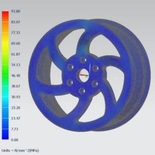
You can also read