New flowing system in cooling system axial-flow pump in a hard coal electric power plant
←
→
Page content transcription
If your browser does not render page correctly, please read the page content below
Journal of Physics: Conference Series

PAPER • OPEN ACCESS

New flowing system in cooling system axial-flow pump in a hard coal
electric power plant
To cite this article: G Peczkis et al 2021 J. Phys.: Conf. Ser. 1741 012006

View the article online for updates and enhancements.

                                This content was downloaded from IP address 46.4.80.155 on 26/01/2021 at 21:08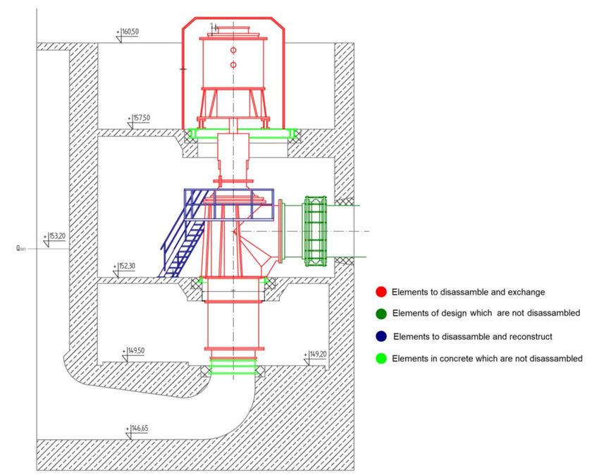
HERVICON+PUMPS 2020                                                                                             IOP Publishing
Journal of Physics: Conference Series                         1741 (2021) 012006          doi:10.1088/1742-6596/1741/1/012006

New flowing system in cooling system axial-flow pump in a
hard coal electric power plant

                     G Peczkis1, T Synowiec1, A Zahorulko2
                     1
                       Institute of Power Engineering and Turbomachinery, Silesian University of
                     Technology, Poland
                     2
                       Sumy State University, 2, R.-Korsakov str., 40007 Sumy, Ukraine

                     E-mail: peczkis@wp.pl

                     Abstract. This article presents the new construction of a centrifugal impeller pump which
                     supplies the cooling system in coal power plants. The article also shows the history of
                     producing this kind if pumps for unified 125 MW and 200 MW power units which dominate in
                     Poland. The process of numerical analysis and conventional calculations leading to the
                     improvement of qualities of the flowing system exceeding literature indicators are presented.
                     The article shows the problems which appeared during assembling the pump in its target
                     workplace. The results of the measurements of the pump flowing system in its target workplace
                     are presented.

1. Cooling system pumps in polish power engineering
The development of traditional engineering, especially of high powers after the World War II in the
1970s brought designs of axial-flow and mixed flow pumps used in cooling systems. The pumps in
cooling systems produced in Poland did not have license but pumps supplying steam boilers were
licensed. The system used in power plants burning coal had high capacity between 145 and
36000 m3/h for mixed flow pumps (type D) and between 420- and 32000 m3/h for axial-flow pumps
(type P) and work at individually selected head of the pump between 7,5 and 90 m for mixed flow
pumps and between 4 and 13 m for axial-flow pumps [4, 7, 8, 17, 18]. Duty point for a pump was set
depending on accepted cooling system from a river, a lake or an artificial water basin. Accepting the
standards of 125 MW and 200 MW power units allowed unification of pumps which were constantly
modernized after operation observation. Because of the political situation in our country the cooling
pumps from the USA and Western Europe were not used. We used only Polish products and
sometimes products from the Eastern Europe. Smaller power plants and thermal-electric power
stations on the area regained after the war, prewar constructions were used- postgerman, permanently
installed in the foundation (for example Marcel thermal-electric power station in Radlin).
    After 1989 during political and economic changes new power units of earlier standards were not built
for almost 20 years. Verified types of pumps were not used. It was explained by the necessity of increasing
the efficiency of energy systems and the requirements of consortiums that were building the power plants.
The result is that changed and modernized cooling systems had different producers and different designs.
Different conditions of mounting pumps are connected with adjusting buildings to pumps and correction of
pumping systems. It means higher full LCC (life cycle costing) in spite of attractive price of the first

              Content from this work may be used under the terms of the Creative Commons Attribution 3.0 licence. Any further distribution
              of this work must maintain attribution to the author(s) and the title of the work, journal citation and DOI.
Published under licence by IOP Publishing Ltd                          1
HERVICON+PUMPS 2020                                                                         IOP Publishing
Journal of Physics: Conference Series           1741 (2021) 012006    doi:10.1088/1742-6596/1741/1/012006

purchase. The pumps delivered to users must be regularly checked and used parts must be changed. Our
local pump producers that had to face the difficulties of economic transformation limited their production
or disappeared from the market. It was wrongly believed that efficient constructions can be designed only
outside Poland, for example in Germany, England or the USA.
    GRUPA POWEN WAFA-POMP SA is the exception that exists on our difficult local market. After
hard times it develops its original activity connected with designing pumps. The company was created
from joined liquidated factories (Pump factories in Warszawa- WAFAPOMP S.A., Świdnica-ŚFPomp
Sp. z o .o. and Zabrze- Fabryka Pomp POWEN Sp. z o. o.) which during the communist times were
monopolists in production of individual types of pumps and service of different types of industry.
    Polish power engineering between 2015 and 2019 was based on 200 MW power units. Those times
there were 50 units of that type. The amount of hours when the unit was used required modernization
or change for the new technology. The real alternative was to build new power units. New high power
coal power units in Opole and Kozienice were built with delay. The idea of building new coal power
unit in Ostrołęka was rejected. It was planned to build a gas power plant. The biggest unit in Jaworzno
was not completed because of technical reasons. The authorities that had different political approach
planned changes in energy producing technology. Unfortunately the ideas were not realized. Nuclear
power plant was not built because there were not any ideas for localization, technology and financing.
It is a general problem in Europe. In EU countries the requirements for safe working conditions during
making the reactors are increased and parts of the constructions which are already made are removed
(Flamanville, France, and Olkiluoto, Finland). Properly working power units are closed because of
non-technological apprehension (Phillipsburg, Germany). There are situations where nuclear power
units are not used (Zwentendorf, Austria). The RES technology which is strongly promoted in Western
Europe does not fulfil the requirements of delivering high power on time because of chimeric
character of the sources of energy (sun, wind) and the lack of profitable high power accumulators [19].
    The answer to the needs of the market and the fact that pumps in coal power plants were worn out,
between 2015 and 2019 a new project appeared. Its result was the new construction of cooling system
pump. This pump fulfilled client’s high requirements and it was not necessary to change the workplace
in the power plant. The basic requirement was the pump work with high capacity at low suction head
and increased efficiency. This task was difficult and demanding.

2. Modernization of axial-flow pumps (type P)
Axial-flow pumps (type P) were produced in alternative designs adjusted to the design of pumping
station. Figures 1 and 2 show examples of pumps. Figure 1 shows low mounting of pump 180P19 and
figure 2 shows high mounting of the same pump.
    Axial-flow pumps used as cooling water pumps in traditional power units have controlled angles of
setting the impeller blades. Thanks to that fact it is possible to adjust the parameters of work to the
present needs of the unit. First controlling systems required stoppage of the pump to set the blades
angle. It was caused by the fact that there were not any possibilities to overcome much higher forces in
blades during motion. This kind of solution was problematic [1, 2, 9, 10]. Nowadays the system with
worn gear and hydraulic system are used. In the systems with worn gear the precision of regulation
depends on drive parameters. In hydraulic systems the change in engine design is required. It is
necessary to hollow the shaft to put high pressure hydraulic hoses there. The changes also include
mounting of the rotating joint and sealing elements of the system what can be problematic [3, 6, 11].
The promising technologies for improving the quality of the surface layer of pump elements are the
methods of alloying [20–22]. The alternative to those systems is the system shown in Figure 3. This
system, just like the hydraulic one, has appreciated by users fluidity and facility of control and it is not
difficult to assemble in contrast to the system used now.

                                                      2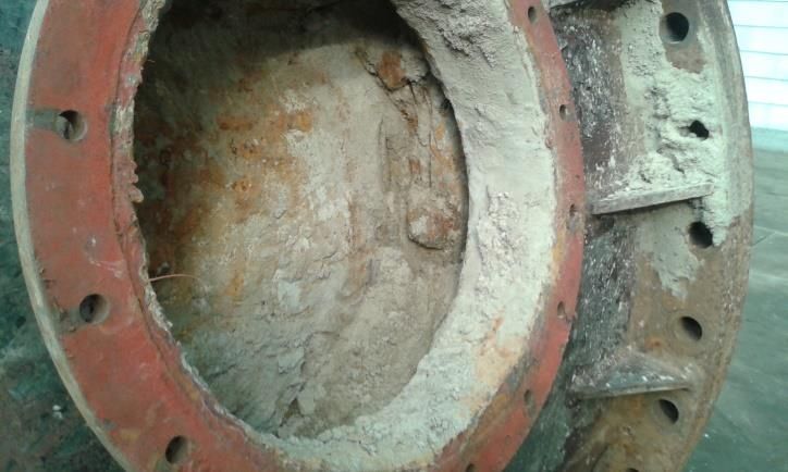
HERVICON+PUMPS 2020                                                                      IOP Publishing
Journal of Physics: Conference Series         1741 (2021) 012006   doi:10.1088/1742-6596/1741/1/012006

   Figure 1. Pump 180P19 with low mounting.             Figure 2. Pump 180P19 with high mounting.

                  Figure 3. New control system of blade-setting angle in the impeller.

                                                    3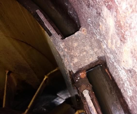
HERVICON+PUMPS 2020                                                                     IOP Publishing
Journal of Physics: Conference Series        1741 (2021) 012006   doi:10.1088/1742-6596/1741/1/012006

   The control can take place during standstill or when the pump works. The blades angle is remotely-
controlled by external control system (for example DCS) which is connected with the laser sensor (4)
and outer hydraulic oil feeder. The sensor (4) has to show the plane motion of the piston (14) in the
cylinder (2) as the blade-setting angle.
   The basic parts of the control mechanism are the piston (14) and the cylinder (2) With the help of
external oil system the oil under pressure is delivered to the upper or lower chamber in the cylinder
(2). The motion of the piston (up or down) depends on which chamber (lower or upper) the oil is
delivered to. The value of piston movement can be measured with the mechanical indicator (29) with
the value shown as the blade-setting angle on the pitch (33) or by the laser sensor (4).
   The operating principle of the mechanism is that rotational speed of the engine is transferred by
the clutch (6,7) on the shaft (16) to the hydraulic unit and the impeller. The impeller blades are
regulated by the pole (17) which moves up or down with the piston (14). The piston moves only by
reciprocating motion. The bearing system (42) and the pusher (27, 32) do not let the rotational
movement of the shaft be transferred to the piston.
   The bearing system is spray-lubricated or put in oil bath in bearing chamber (130). The oil is
cooled by the cooling system (40). The indicator (45) shows the level of the oil in the chamber (130).
The temperature is measured with a thermometer (53).
   The bearing system lets the piston move in reciprocating motion and it transfers the motion on
rotating pole (17) without changing the load of the axial bearing in the pump. The bearing system is
set on the intermediate shaft (16) by a sleeve (9) which rotates with the shaft by using parallel key
(43). The sleeve can move along the intermediate shaft (16) [12, 14, 16].

                Figure 4. The scheme of demolishing foundation to mount new cooling
                                water pump 180P19 for 200 MW unit.

                                                   4
HERVICON+PUMPS 2020                                                                       IOP Publishing
Journal of Physics: Conference Series          1741 (2021) 012006   doi:10.1088/1742-6596/1741/1/012006

   Figure 5. The scheme of demolishing foundation to mount new cooling water pump 180P19 for
                                         500 MW unit.

   Changes in power requirements throughout a year and decrease of water level in rivers in summer
when the demands for cooling are much higher than in winter connected with the necessity of
increasing the efficiency of systems producing energy caused changes in work parameters required by
power plants. For a couple of years, in biddings for modernization of cooling water pumps there have
been requirements for higher capacity, higher head of the pump, operation without cavitation at lower
suction head, higher efficiency. The increase of work parameters caused the increase of ceiling load
because of higher hydraulic forces and bigger weight of used higher power engines. During each
modernization the analysis of the ceiling load capacity was carried out to check if additional structural
reinforcement of the pumping station is necessary [5, 11].
   The starting point in modernizing the construction was the full changeability of the stand what
decreased the interference in existing pumping station construction. It also made using the existing
machines connected with the pumps possible. Figures 4 and 5 show the plan of demolition during the
modernization of cooling water pumps for 200 MW and 500 MW units.
   The increase of capacity and stand changeability which meant maintaining the outer diameter
required increase of speed on particular intersections what made the suction properties worse. They
had to be corrected because of lower water levels in rivers. The shape of supply chamber and the outer
diameter of the flowing system mounting were supposed to be without any changes. On the inlet to the
impeller only the shape of the hub was modernized. The changes in the hub are shown in
Figure 6 [13, 15].

                                                    5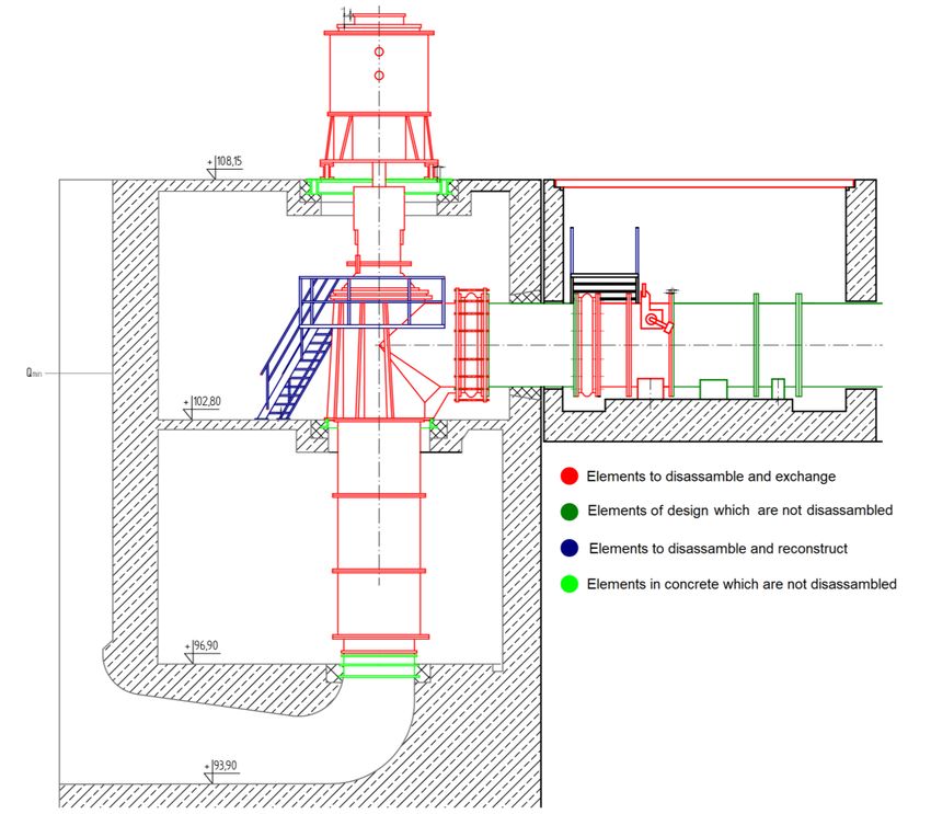
HERVICON+PUMPS 2020                                                                         IOP Publishing
Journal of Physics: Conference Series           1741 (2021) 012006    doi:10.1088/1742-6596/1741/1/012006

             Figure 6. The impeller unit in pump 180P19 before and after modernization:
1 – impeller blade, 2 – impeller hub, 3 – slide, 4 – lever, 5 – fairwater, 6 – external impeller sleeve,
           7 – internal impeller sleeve, 8 – pilot sleeve, 9 – pilot sleeve, 10 – disc, 11 – nut,
                                         12 –impeller blade nut.

                                                      6
HERVICON+PUMPS 2020                                                                         IOP Publishing
Journal of Physics: Conference Series           1741 (2021) 012006    doi:10.1088/1742-6596/1741/1/012006

    The significant increase of parameters was achieved by innovative design of impeller blades and
diffuser and modernization of elbow insert what is shown in Figure 7.

               Figure 7. The picture of elbow insert in pump 180P19 after modernization.

                             Figure 8. The flowing system in pump 180P19:
                      1 –layer- lower part; 2 – layer- upper part; 3 – bearing sleeve;
                           4 – diffuser; 5 – bushing; 6 – impeller unit; 7 – pole.

                                                      7
HERVICON+PUMPS 2020                                                                     IOP Publishing
Journal of Physics: Conference Series        1741 (2021) 012006   doi:10.1088/1742-6596/1741/1/012006

   The starting point to design the flowing system was 2D analysis of innovative counting method
results. Then 3D geometry and CFX analysis were prepared.

3. Problems with mounting pump in the workplace of the previous pump
Full changeability of the stand lets the pump parameters increase only by changing internal parts, but
during the modernization, which theoretically should be carried out without any problems, there are
difficulties caused by designing changes made by pump users during long using and adjusting the
pump to requirements of internal repair services. The example of such changes can be access openings
which some users introduced to pumps they used (Fig. 9).

           Figure 9. Access openings and sediment in the flowing system after proper using.

In places where the pumps were used local repair services made construction changes inconsistent
with the producer’s recommendations. Figure 10 shows welded parts of the pump. Their permanent
connection was rejected by the pump designers.

   Figure 10. Welded connection of pump elements during local repairing by unauthorised services.

    Pumps which were first designed according to the same documentation after years of using in
different places turn to be new modified constructions. These pumps are a big challenge for the
designers and services when they have to exchange elements in the pump. Some of changes made by
users had unfavorable influence on the pump efficiency.
    The real problem is maintaining the requirements of EN ISO 9906 for demanded measurements
grades during both capacity and pressure measurements. During pressure measurements it is difficult

                                                   8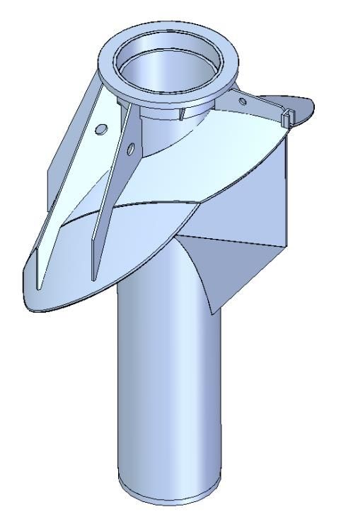
HERVICON+PUMPS 2020 IOP Publishing
Journal of Physics: Conference Series 1741 (2021) 012006 doi:10.1088/1742-6596/1741/1/012006
to find required distance between the pump branch and the place of measurement. Also the pipes
leading to the collector are often choked. During efficiency measurements the requirements connected
with keeping specific length of line segments in front of and behind flowmeter are not kept and it is
not certain that there are not any leaks between the pump and the flowmeter. The example of a leak is
shown in Figure 11.
Figure 11. Leak of water on new throttle of pumping system.
It was a leak in new throttle which separated modernized pump from the collector. It was not
certain that the throttles of the other pumps working on the same collector as the modernized one are
leak proof and the indications on the flowmeter during testing show real capacity of the pump. The
answer to this problem is testing the pump at the producer’s test stand. The requirements for higher
efficiency with higher measurements grades appearing in biddings without certainty that the
measurements at the power plant show real parameters were one of the reasons to create Research and
Development Centre in 2014. This makes testing pumps that have power between 0,2 kW to 5 MW
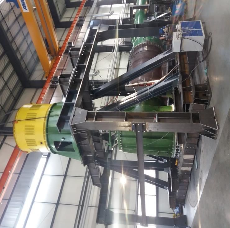
possible. The biggest diameter of the outlet branch can be 2000 mm. Figure 12 shows the stand which
was built to test series of pumps P and D.
Figure 12. The stand to test pumps P and D on new testing station in
GRUPA POWEN-WAFAPOMP S.A.
9HERVICON+PUMPS 2020 IOP Publishing
Journal of Physics: Conference Series 1741 (2021) 012006 doi:10.1088/1742-6596/1741/1/012006
Table 1 shows the table with measurements of cooling system pumps before and after
modernization and changes. In the power plant In Kozienice 4 pumps in units 9 and 10 were changed.
The measurements made by independent research centre confirmed obtaining expected effect. In the
power plant in Połaniec 1 pump was changed obtaining effective desired change of parameters.
Table 1. The comparison of pump parameters before and after modernization.
Location of Block Modernization Volume Head Rotation
the power power flow (m) speed
plant (m3/h) (rev/min)
Kozienice 500MW Before 30 000 10.6 370
Kozienice 500MW After 29 000 14 370
Połaniec 225MW Before 30 000 9.6 370
Połaniec 225MW After 30 000 15 370
4. Conclusion
The process of calculating and designing new flowing system in the cooling system pumps described
in this article was planned to take 1 year. Practically the complexity of designing process and long
process of numerical calculations on models, which results were reliable, took 2 years. Designers
appreciate the meaning of numerical programs to make machines efficiency higher. They also
emphasize that it takes a lot of time to achieve desired results mainly because of constraints of
numerical machines. Realization of purchase order for pumps which because of their size are not
available immediately required cooperation between scientists and designers.
GRUPA POWEN-WAFAPOMP S.A. with its long experience and modern technological facilities
made the designing and making of new flowing system efficient.
References
[1] Martsynkovskyy V 2005 Annular Seals (SSU: Sumy)
[2] Martsynkovskyy V 2002 Hydrodynamics of throttling channels (SSU: Sumy)
[3] Zahorulko A 2015 Experimental investigation of mechanical properties of stuffing box packings
Sealing Technology 8 7
[4] Jędral W 2001 Pompy Wirowe
[5] Jędral W 2018 Efektywne energetycznie układy pompowe (Warszawa: Oficyna Wydawnicza
Politechniki Warszawskiej)
[6] Korczak A 1997 Szczeliny w Maszynach Hydraulicznych Pompy Pompownie 2
[7] Korczak A 1996 Ocena dobór i eksploatacja pomp wirowych Zeszyty Naukowe Pol.Śl.
„Energetyka” 127
[8] Łazarkiewicz Sz, Troskolański A T 1968 Pompy Wirowe (Warszawa: WNT)
[9] Varchola M, Hlbocan P 2016 Hydraulicky Navrh Odstredivych cerpadiel: Monografia
(Bratislava)
[10] Varchola M 1979 Prúdenie v radiálnom hydrodynamickom čerpadle (Kandidátska Dizertačna
práca, Strojnicka fakulta SVŃT Bratislava)
[11] Gryboś R 1996 Drgania Maszyn Skrypt Uczelniany Nr 2009 (Gliwice: Politechnika Śląska)
[12] Chodkiewicz R, Papierski A 2001 CFD Code A Useful Tool for the Turbomachinery Designer
Seminar/Summer School CFD for Turbomachinery Applications
[13] CFX-TASCflow Theory Documentation Version 2.12 (Waterloo, AEA Technology
Engineering Software Limited) N2L 5Z4
[14] Chmielniak T, Korczak A, Papierski A, Peczkis G 2006 Investigations of the flow through the
sealing face clearance International Scientific Symposium Hydrodynamic Theory of Lubrication
–120th Anniversary
[15] Kazimierski Z 1992 Numeryczne wyznaczanie przepływów turbulentnych (Wrocław:
Ossolineum)
10HERVICON+PUMPS 2020 IOP Publishing
Journal of Physics: Conference Series 1741 (2021) 012006 doi:10.1088/1742-6596/1741/1/012006
[16] Korczak A, Martsynkovskyy V A 2004 Buffer balancing device of a centrifugal compressor
rotor Proceedings of XIII International Scientific Conference on Pump and Compressor
Machinery (Sumy, Ukraine)
[17] Stepanoff A J 1957 Centrifugal and Axial Flow Pumps (John Wiley & Sons)
[18] Świtalski P, Wojtyna M 2001 Pompy i Pompownie 4 (102)
[19] Wiech J 2019 Energiewende Nowe niemieckie imperium (TS Wydawnictwo Tomasz Szukała)
[20] Tarel’nik V B, Paustovskii A V, Tkachenko Y G et al. 2018 Electrospark graphite alloying of
steel surfaces: technology, properties, and application Surf. Engin. Appl. Electrochem. 54
147-156
[21] Kirik G V, Gaponova O P, Tarelnyk V B et al. 2018 Powder Metall Met Ceram 56 688
[22] Konoplianchenko Ie, Tarelnyk V, Martsynkovskyy V, Belous A, Gerasimenko V, Smolyarov G,
Tolbatov A, Tolbatov V, Chuprina M 2020 Changing cohesive energy between atoms in metal-
to-metal transition layer for Fe–Sn and Fe–Cu–Sn compounds in the course of spark alloying
process Pogrebnjak A, Bondar O eds. Springer Proceedings in Physics 240 pp 117-133
11You can also read