INTERSEPTOR (IMF) SERIES FILTER SYSTEM OPERATING & MAINTENANCE MANUAL - INTERSEPTOR SERIES HIGH EFFICIENCY MEDIA FILTRATION SYSTEM
←
→
Page content transcription
If your browser does not render page correctly, please read the page content below
InterSeptor (IMF) Series Filter System
             Operating & Maintenance Manual

                           InterSeptor Series High
                  Efficiency Media Filtration System

PEP Filters • 322 Rolling Hill Road • Mooresville, NC 28117 • 800-243-4583 • www.pepfilters.com
IMF Series Filter System
Operating & Maintenance Manual
TABLE OF CONTENTS
Construction Detail………………………………………………………………………….. Cover
General Description.………………………………………………………………………… 3
Filter Operation……………………………………………………………………………… 3
Installation:
Rigging……………………………………………………………………………………… 4
Loading Media……………………………………………………………………………… 4
Piping……………………………………………………………………………………….. 5
Electric Actuator Requirements
Wiring……………………………………………………………………………………….. 6
Electrical Requirements…………………………………………………………………… 6
Operation and Maintenance……
Initial and Seasonal……………………………………………………………………….. 7
Start-up…………………………………………………………………………………….. 7
After First Hour of Operation………………………………………………………… 8
Operation…………………………………………………………………………………… 8
Cold Weather Operation…………………………………………………………………. 8
Seasonal Shutdown……………………………………………………………………….. 9
Maintenance Procedures:
Pump Pre-Strainer……………………………………………………………………… 9
Pump………………………………………………………………………..……………… 9
Backwashing………………………………………………………………………………. 9,10
Water Treatment…………………………………………………………………………… 11
Factory Authorized Parts………………………………………………………………… 11
SAFETY PRECAUTIONS…………………………………………………………………..
Warranty…………………………………………………………………………………….. 12
Operation & Maintenance Schedule………………………………………………… 13
Tables…………………………………………………………………………………………. 14 ~ 15
PEP Filters • 322 Rolling Hill Road • Mooresville, NC 28117 • 800-243-4583 • www.pepfilters.com
Rev. 031502
2 of 15IMF Series Filter System
Operating & Maintenance Manual
GENERAL DESCRIPTION
PEP IMF series high efficiency filters are permanent media type units specifically
designed to remove suspended particulates down to 0.45 micron from industrial and
process water. IMF filters are suitable for both side-stream and in-line applications on
pressurized systems. The standard pressure rating for IMF filter systems is 150 psig
(1,050kPa). The filter vessel is constructed of 304 stainless steel to ASME Section VIII,
Division I standards. Higher pressure ratings are available. The filter vessel internals
are also constructed of 304 stainless steel. The filter vessel has a conical bottom with
an annular ring under drain that is flush with the cone bottom. Because the under drain
is flush with the filter vessel bottom, this unique design eliminates stagnant water below
the under drain.
Filter Operation
Unfiltered system water is pumped to the IMF filter tangential inlet. Water enters the
filter vessel in a swirling motion that separates the larger and heavier particles from the
liquid and keeps them to the media bed perimeter. Water then flows through the media
bed and suspended particles are trapped within the filter media. The resulting filtered
water passes from the vessel through the radial bed fluidizers and annular ring under
drain at the bottom of the filter and the filtered is returned to the system.
When trapped particles cause the pressure differential across the media bed to reach a
pre-determined pressure of approximately 16 psig, the filter valves automatically
reposition and the media is fluidized in reverse flow. The accumulated particulate exits
the filter vessel via the tangential inlet and flows to a suitable drain. After which, the
valves automatically reposition and filtration continues. Depending on backwash flow
rate, the filter may backwash anywhere from 90 seconds to three minutes (field
selectable).
Installation
Unpacking
Immediately upon receipt, the PEP IMF filter should be checked thoroughly to ensure
that all required items have been received and the filter equipment is free from
transportation damage prior to signing the bill of lading. The filter serial number is
located on a label affixed to the top inside of the control panel enclosure. Check the
serial number on the label with the invoice/packing list to assure they match.
PEP Filters • 322 Rolling Hill Road • Mooresville, NC 28117 • 800-243-4583 • www.pepfilters.com
Rev. 031502
3 of 15IMF Series Filter System
Operating & Maintenance Manual
Rigging
The PEP IMF units should be lifted with a forklift or overhead crane.
Note: The lifting lugs located on either side of the filter vessel should be used when
lifting the filter vessel only. The vessel must be empty of all water and media. If
these units are lifted with an overhead crane, the filter vessel must be removed from
the base and lifted separately. Lifting straps must be located below the base and
should not come in contact with filter components (pump, face piping, control panel,
etc.).
All PEP water filters should be anchored to the floor by means of anchor bolts. The
IMF base has holes suitable for 1/2" anchor bolts.
After the unit has been installed, locate the pressure gauge and air relief valve
(shipped inside the control panel) and install them on the top of the filter vessel.
Media Loading
Note: Never load filter media or gravel into a dry filter vessel. Fill the vessel with
water approximately one foot above the stainless steel laterals before loading media.
Refer to the drawing on the cover of this manual to see the location of the laterals.
This will help to minimize dust and will also take some of the energy out of the
media as it falls into the vessel, preventing possible damage to the internal piping.
Media is loaded into the filter vessel through the top access port on the filter vessel
Four different types of media are supplied with the filter. The loading sequence is as
follows: Unifill 475, Unigran 55, Unigran 85 and last, Unigran 20.
Refer to Table 6 for the recommended quantities of media for each filter model.
The specially manufactured spherical silica sand media used in PEP InterSeptor
media filters is designed to remove suspended solids 0.5 micron and larger, over
90% by volume. The media will ship to the job site in ½ cubic ft. pails (50 lbs/23 kg)
or 1 cubic ft. bags (100 lbs/46 kg) for ease of handling during the media loading
process.
Actual quantities may vary slightly with vessel pressure ratings. Correct quantities
will be noted on the shipping and inspection records for each system. Always check
integrity of filter internals before loading media.
PEP Filters • 322 Rolling Hill Road • Mooresville, NC 28117 • 800-243-4583 • www.pepfilters.com
Rev. 031502
4 of 15IMF Series Filter System
Operating & Maintenance Manual
Piping
The PEP IMF filter should be installed as follows:
1. Connect a feed water line from the system sump or piping to the connection
labeled "Inlet" on the pump. If the inlet connection is located above the
operating water level of the system sump, install a foot/check valve to prevent
pump suction loss.
2. Connect the return line from the connection labeled "Outlet" to the system
sump or piping.
3. A service valve should be installed on the inlet, outlet, and city water line (if
city water is used for backwash) to allow filter servicing. For units using a
backwash source other than the system matched pump, refer to the
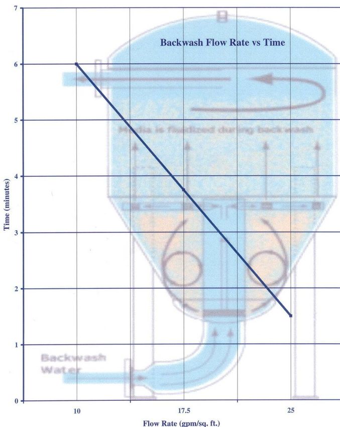
Backwash Flow Rate vs Time graph to determine the required backwash flow
rate. Connect this line to the fitting labeled "City Water". The maximum city
water backwash supply pressure on the IMF filters should never exceed the
pressure rating of the filter vessel. If public or municipal water is used for
backwash, a reduced pressure back-flow prevention or check valve is required
in the line (refer to local codes).
Connect a backwash waste line to the connection labeled "Waste". This line
carries the backwash wastewater to the drain. Do not put a valve in the
backwash line and never reduce the backwash line size.
Note: If the drain is not large enough to handle the backwash flow rate, it may
be necessary to use a backwash holding tank to collect the wastewater, and
regulate the flow from the holding tank to drain.
4. All interconnecting piping, fittings, valves, or other accessories connected to
the filter system (whether supplied by PEP or others) must be independently
supported to eliminate stress on piping.
Check with local, county, or other government authorities to ensure compliance with
applicable government or industry codes.
Note: The ¾” (20 mm) drain plug on IMF units is located on the tank bottom outlet.
PEP Filters • 322 Rolling Hill Road • Mooresville, NC 28117 • 800-243-4583 • www.pepfilters.com
Rev. 031502
5 of 15IMF Series Filter System
Operating & Maintenance Manual
Actuator Requirements
PEP IMF filters utilize electric actuators to control the valve action between the
filtration and backwash cycles. The electric actuator is designed for 110 VAC control.
Wiring
IMF filters are supplied with a pump and automatic backwash controls and the
following system components: NEMA 4X (IP32) control enclosure containing an
on/off disconnect switch, motor overload protection, transformer to provide 110 VAC
control voltage, adjustable backwash timer, 24 hour time clock, pressure differential
switch to initiate backwash, valve actuator to reposition valves for backwash, and
push button for manual backwash initiation. Units are provided with 460 VAC, 3φ
close-coupled pump/motor assembly.
IFM filter units configured for using city water backwash are provided with a
magnetic motor starter.
The following recommendations conform to the 1993 national electric code. Check
with local, county, or other government authorities for prescribed requirements.
Note: Refer to the pump/motor nameplate for horsepower and current draw.
Single and Three Phase Automatic Units
Install a separate power supply line with circuit breaker protection between the
closest branch distribution panel and the control box. The full load current for
standard single and three phase units is listed in Tables 4 & 5. The control box
contents are pre-wired and include a service disconnect switch, thermal
overload/short circuit protection, and a transformer to convert the power supply to
single phase 110 VAC for controls (for pump motor voltages other than 110 VAC).
Wire the power supply lines to the disconnect switch. All incoming power supply
lines must connect to the door interlock disconnect.
PEP Filters • 322 Rolling Hill Road • Mooresville, NC 28117 • 800-243-4583 • www.pepfilters.com
Rev. 031502
6 of 15IMF Series Filter System
Operating & Maintenance Manual
Operation And Maintenance
Initial And Seasonal Start-Up
Before initial start-up or after a shut down period, the IMF filter should be thoroughly
inspected and cleaned.
Caution: Perform the first five of the following recommendations with power off.
Refer to the Safety Precautions on Page 8, regarding the safeguarding of
maintenance personnel from biological contaminants, prior to initial and seasonal
start-up.
1. Loosen the bolts around the pump pre-strainer (if equipped) tank lid. Remove
the lid, inspect the O-ring seal and lubricate. Clean debris from the pump
pre-strainer basket. Prime the pump suction line by filling the strainer basket
housing. Replace the basket, lid and bolts.
2. Turn the pump and motor shaft by hand to ensure free rotation (if possible).
3. On PEP filters, loosen the access bolts on access port lid, remove lid and
lubricate the bolts as necessary.
4. Inspect the filter vessel internals and media pack. If the media pack is
contaminated, remove the foreign material or replace the media, and re-install
the top access port.
5. Open manual air relief valve on top of the filter tank. Start the pump motor
briefly and check the arrow on the pump volute for proper rotation. Turn the
pump motor off. Do not operate the pump for an extended period of time
with the pump rotating backwards. Have a qualified electrician change leads
to correct rotation.
6. With the air relief valve open on top of filter tank, check the shut-off valves in
the filter inlet and outlet water lines to verify they are open. Make sure the
pump is primed. Start the pump and allow the filter vessel to fill. Wait for all
air in vessel to be released before closing the manual air relief valve.
7. Check the voltage and current of all leads on the pump motor. The current
amp draw should not exceed the pump motor nameplate rating.
8. Check the unit for any unusual noise or vibration and contact your local PEP
Representative if noise or vibration occurs.
9. Check the unit for any air or water leaks. Leaks must be repaired. Failure to
do so could result in poor performance and/or personal injury.
10. Backwash the filter. After back washing the filter, check and record the inlet
and outlet pressure gauge readings. The media should be back washed
PEP Filters • 322 Rolling Hill Road • Mooresville, NC 28117 • 800-243-4583 • www.pepfilters.com
Rev. 031502
7 of 15IMF Series Filter System
Operating & Maintenance Manual
whenever the pressure drop across the filter (the difference between the two
gauges) reaches approximately 16 psig.
After First Hour Of Operation
1. Open the air relief valve on top of the filter tank. Close the valve after the air
has been purged from the system. Excessive air release represents a leak in
the pump suction piping, and must be repaired. Air accumulation in the filter
tank can result in an unsafe condition due to excessive pressure within the
tank.
2. Check the unit for any unusual noise or vibration and contact your local PEP
Representative if noise or vibration occurs.
3. Check unit for any air or water leaks.
Operation
During operation, PEP IMF filters should be inspected, cleaned and lubricated on a
regular basis. The required services and recommended frequency minimums for
each are summarized in the Operation and Maintenance Schedule in this manual.
Cold Weather Operation
IMF filters exposed to below freezing ambient temperatures require freeze
protection. Installation in a heated indoor space is the best means of preventing the
water from freezing in a filter. Where indoor installation is impractical because of
filter location or space limitations, supplementary heat must be supplied through the
use of electrical heat tape and insulation. The parts of the filter that must be heat
traced and insulated are: pre-strainer tank, pump, piping, valves, pressure switch
tubing, and filter vessel. The unit should be drained when shut down for any period
of time. Refer to the Seasonal Shutdown section of the manual for
recommendations.
PEP Filters • 322 Rolling Hill Road • Mooresville, NC 28117 • 800-243-4583 • www.pepfilters.com
Rev. 031502
8 of 15IMF Series Filter System
Operating & Maintenance Manual
Seasonal Shutdown
The following services should be performed if the unit is shut down for a prolonged
time period.
1. Shut off all electrical power.
2. Close the shut-off valves in the filter inlet and outlet water lines. For units
using a backwash source other than the system, close the shut-off valve in
the line from that source.
3. Drain all external piping to and from the filter.
4. Open the manual vent valves and the drain line to the filter tank and piping.
After the water has drained, close the drain and vent.
5. Loosen the bolts that hold the filter access lid in place and remove the
inspection port cover. Lubricate the bolt and replace the port gasket if
necessary.
6. Inspect the filter vessel internals and media pack. If the media is
contaminated, remove the foreign material and replace the media if
necessary. Install the filter access port and secure the bolts.
Maintenance Procedures
Pump Pre-Strainer (if equipped)
Warning: Disconnect all electrical power prior to performing pump maintenance.
The filter pre-strainer basket on the pump inlet must be kept clean and free of
debris. Shut off the power, close the valves, open the air relief valve, remove bolts
and lid. Remove and clean the basket. Replace basket, lubricate O-ring, and tighten
bolts.
Backwashing
The filter media will backwash when the differential pressure is reaches
approximately 16 psig. The backwash cycle on automatic units can be manually
initiated by pushing the button on the control panel until the valves change position.
The valves will then automatically reposition to filter mode after a preset interval
(typically 90 seconds to six minutes, as determined by the backwash flow rate. IMF
filters should be back washed at least once every three days.
PEP Filters • 322 Rolling Hill Road • Mooresville, NC 28117 • 800-243-4583 • www.pepfilters.com
Rev. 031502
9 of 15IMF Series Filter System
Operating & Maintenance Manual
IMF 24 (gpm) 0 31.4 43.2 55 66.7 78.5
IMF 30 (gpm) 0 49.1 67.5 85.9 104.3 122.7
IMF 36 (gpm) 0 70.7 97.2 123.7 150.2 176.7
PEP Filters • 322 Rolling Hill Road • Mooresville, NC 28117 • 800-243-4583 • www.pepfilters.com
Rev. 031502
10 of 15IMF Series Filter System
Operating & Maintenance Manual
Filter Tank
The filter tank internal components should be visually inspected annually or
whenever back washing does not reduce the pressure of the filter tank to the
starting media gauge pressure. On IMF filters, remove the access port on top of the
tank to inspect internal components.
Note: Always use care and follow proper shutdown procedures. Remove and
inspect the media. IMF filters have hand access ports located on the top and side
bottom of the tank to facilitate media removal. Over a period of time, foreign matter
may become embedded in the media pack that will not back wash. Contaminated
media should be discarded. Load the filter vessel with the proper amount of new
media, following the media loading instructions.
Water Treatment
Filtration is an effective way of reducing suspended particulates in fluids but is only
one important component in an effective water treatment program. Dissolved solids
originally present in water remaining after evaporation cannot be eliminated by
filtration. Concentration of these dissolved solids increase rapidly and can cause
scale and corrosion. In addition, airborne impurities and biological contaminants,
including Legionella, may be introduced into the re-circulating water through the
cooling equipment being filtered.
To control potential contaminants, a water treatment program must be employed.
In many cases a simple bleed-off in the system may be adequate for control of scale
and corrosion. The filter backwash typically constitutes a portion of the bleed.
Biological contamination can be controlled through the use of biocides or other types
of control and such treatment should be initiated at system start-up and
incorporated into the total treatment system regime.
For specific recommendations on water treatment, it is recommended to consult with
a water treatment specialist.
Factory Authorized Parts
PEP maintains a stock of replacement parts. Parts usually ship within one to three
business days after receipt of order. In emergency situations, shipment can usually
be made within 24 hours (if stock). To expedite your parts order, please
include the unit serial number and model when ordering parts.
PEP Filters • 322 Rolling Hill Road • Mooresville, NC 28117 • 800-243-4583 • www.pepfilters.com
Rev. 031502
11 of 15IMF Series Filter System
Operating & Maintenance Manual
Recommended Spare Parts
O-ring/gasket for filter tank top access port and hand hole gaskets.
O-ring seal/gasket for pump pre-strainer lid (if equipped).
Seal kit for pump
Transformer fuse
Safety Precautions
All electrical, mechanical and rotating machinery constitute a potential hazard,
particularly for those not familiar with its design, construction, and operation.
Accordingly, adequate safeguards should be taken whenever working with or near
IMF filter systems.
Equipment operation, maintenance and repair should be undertaken by qualified
personnel only. All such personnel should be thoroughly familiar with the
equipment, the associated system and controls, and the procedures set forth in this
manual. Proper care, procedures, and tools must be used in handling, lifting,
installing, operating, maintaining, and repairing the IMF filter system.
For the protection of authorized service and maintenance personnel, the pump motor
associated with this equipment should be installed with a lockable disconnect switch
located in close proximity and within sight of the IMF filter. No service work should
be performed on or near the pump motor without first ensuring that the pump motor
has been electrically disconnected and locked out.
The re-circulating water system may contain chemicals or biological contaminants
that could be harmful if inhaled or ingested. Accordingly, personnel exposed to the
mist produced by water jets or compressed air (should these be used to clean
portions or components of the IMF filter) should wear half-face respirators with HEPA
filter cartridges, NIOSH/MSHA approved number TC-21C-142/TC-21C-182.
Warranty Policy
The PEP InterSeptor Series Media Filter vessel and internals are warranted to be free
from defects in materials and workmanship for a period of 15 years after shipment.
All other system components are warranted against defects in materials and
workmanship for 12 months from date of startup or 18 months after shipment,
whichever occurs first. Damage due to corrosion is not covered. Contact PEP Filters
for further warranty information.
PEP Filters • 322 Rolling Hill Road • Mooresville, NC 28117 • 800-243-4583 • www.pepfilters.com
Rev. 031502
12 of 15IMF Series Filter System
Operating & Maintenance Manual
OPERATION AND MAINTENANCE SCHEDULE
TYPE OF SERVICE START- MONTHLY SEMI- SHUTDOWN ANNUALLY
UP ANNUALLY
Inspect General Condition of Unit X X
Check & Lubricate Clamp on Strainer
Lid (if equipped)
X X X X
Clean Basket in Pre-Strainer Tank (if
equipped))
X X X X
Check Pump Shaft for Free Rotation X X
Check Operation of Valves X X X
Check, Lubricate Clamp on Filter
Tank Access Port
X X X
Inspect Media Pack X X X
Check Pump Motor for Proper
Rotation
X
Prime Pump X
Check Motor Voltage & Current X X X
Check Pressure Gauge Readings
(Top of Filter Tank & outlet)
X X
Check Unit for Unusual Noise or
Vibration
X X
Check Unit for Leaks X X
Drain Filter and Piping X
Table 1 Inspection Chart
PART IMF MODEL
Filter Tank X
Valves & Linkage X
Filter Inter-connection Piping X
Pump Pre-strainer tank & basket (if equipped) X
Pump X
NEMA 4X Box (Auto only) X
Filter Skid X
Pressure gauges, air relief valves, & tees X
Media (shipped separately) X
PEP Filters • 322 Rolling Hill Road • Mooresville, NC 28117 • 800-243-4583 • www.pepfilters.com
Rev. 031502
13 of 15IMF Series Filter System
Operating & Maintenance Manual
Table 2 Connection Sizes
System Water Backwash City Water
IMF
Backwash
Model
Pump Inlet Filter Outlet Waste Outlet Inlet City Water
IMF Inches/mm
24 2.5/63.5 2/50.8 2/50.8 2/50.8
30 2.5/63.5 2.5/63.5 2.5/63.5 2..5/63.5
36 3/76.2 3/76.2 3/76.2 3/76.2
Table 3 Filter Flow Rates
IMF Forward Flow Minimum Backwash Flow Rate Maximum Backwash Flow Rate
Model gpm / lps gpm / lps gpm/lps
24 79/5.98 32/2.4 79/5.98
30 123/9.3 49/3.7 123/9.3
36 178/13.5 71/5.38 178/13.5
Table 4 Electrical Requirements (1φ, 60 Hz.)
PUMP HP/KW Voltage 1φ 60/50HZ Full Load Current
(Amps)
2/1.5 115, 208, 230 24, 13.2, 12
3/2.25 208, 230 18.7, 17
Table 5a Electrical Requirements (3φ, 60Hz)
PUMP Voltage 3φ Full Load
HP/KW 60 HZ Current (AMPS)
2 / 1.5 208, 230, 460, 575 7.5, 6.8, 3.4, 2.7
3 / 2.2 208, 230, 460, 575 10.6, 9.6, 4.8, 3.9
5 / 3.7 208, 230, 460, 575 16.7, 15.2, 7.6, 6.1
Table 5b Electrical Requirements (3φ, 50Hz)
PUMP Voltage 3φ∅ Full Load
HP/KW 50 HZ Current (AMPS)
2 / 1.5 380, 415 3.4, 3.1
3 / 2.2 380, 415 5.2, 4.7
5 / 3.7 380, 415 8.0, 7.1
Table 6 Media Quantities for IMF Filters
IMF Model Unifill 475 Unigran 55 Unigran 85 Unigran 20
24 4 2 2 1
30 7 3 3 1.5
36 11 4 4 2
PEP Filters • 322 Rolling Hill Road • Mooresville, NC 28117 • 800-243-4583 • www.pepfilters.com
Rev. 031502
14 of 15IMF Series Filter System
Operating & Maintenance Manual
DESCRIPTION PART NUMBER
Filter Parts
Gauge Kit (Includes: 4 way cross, pressure gauge, air vent & petcock) A-Z-VNT-GA-IMF-100
Top Hand Hole Gasket 6X8 IMF 24 & 30 G-GSKT-06X08-NE-OVAL
Top Manway Gasket 11 X 15 IMF 36 G-GSKT-11X15-NE-OVAL
ACTUATOR-Filter Models Unitorq
Electric Actuator IMF 24, 30, & 36 Q-ACT-E-0600-110-R600
PUMP PARTS:
2½" Cast Iron Pre-Strainer w/ Basket IMF 24 & 30 P-STR-0250-FLG-CI125
2½" Stainless Steel Perforated Pre-Strainer Basket only P-STR-0250-BSKT-125
3" Cast Iron Pre-Strainer w/ Basket IMF 36 P-STR-0300-FLG-CI125
3" Stainless Steel Perforated Pre-Strainer Basket Only P-STR-0300-BSKT-125
Filter Model Pump/Motor Assembly
3 HP IMF 24 79 gpm 220,460/3/60 R030-S009850-TC46036
3 HP IMF 30 123 gpm 460/3/60 R030-S014250-TC46036
5 HP IMF 36 178 gpm 460/3/60 R050-S019250-TC46036
Electrical Components
Differential Pressure Switch E-SWTC-DFP-150-165
Backwash Timers:
backwash timer E-TIMR-600-DIV
Replacement for Omron Backwash Timer E-TIMR-600-OMR-REPLC
Syrelec (Conversion kit to SSAC) E-TIMR-600-SYR
24 Hour Time Clock / Grasslin 60HZ only E-CLCK-24H-120
24 Hour Time Clock 50HZ only E-CLCK-24H-QTZ
PEP Filters • 322 Rolling Hill Road • Mooresville, NC 28117 • 800-243-4583 • www.pepfilters.com
Rev. 031502
15 of 15You can also read