CHRYSLER PACIFICA SECONDAY CONTROLS INSTALLATION GUIDE
←
→
Page content transcription
If your browser does not render page correctly, please read the page content below
CHRYSLER PACIFICA
                           SECONDAY CONTROLS
                           INSTALLATION GUIDE

                                                                                                  LAST UPDATED August 9, 2018

                                                                                                               YouTube Link: Video Link

                                                  2017© R.A.SH Tronics Ltd. All rights reserved.
Reproduction by any means, electronic, graphics (GUI) or mechanical, including photocopying, recording or by any information storage and retrieval
                 system or translation in whole or part is NOT PERMITTED without written authorization from R.A.SH Tronics Ltd.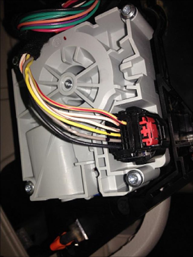
TABLE OF CONTENTS
2 ...............................................................................................................................................TABLE OF CONTENTS
3 ................................................................................................................................... TO OUR VALUED CUSTOMER
3 ....................................................................................................................................... CUSTOMER CARE CENTER
3 .............................................................................................................................................................. ABSTRACT
3 ........................................................................................................................................................ USEFUL HINTS
4 ...................................................................................................................... SECONDARY CONTROLS DEFENITIONS
5 ........................................................................................................................................SYSTEM BLOCK DIAGRAM
6 ..................................................................................................................... DESCRIPTION OF MAIN COMPONENTS
7 .................................................................................................. DESCRIPTION OF MAIN COMPONENTS CONTINUED
8 .................................................................................................................................. CAN-BUS GATEWAY MODULE
9 ...................................................................................................................CAN-Bus Powered gear selector module
10 ................................................................................................................................... CANbus GATEWAY WIRING
11 .............................................................................................................................. PUSHBUTTON START MODULE
11 .............................................................................................................................. Using the start stop function
11 .................................................................................................. MODIFYING THE ENGINE START STOP MODULE
12 ............................................................................................................................. ENGINE START STOP WIRING
13 ................................................................................................................................... MULTI-FUNCTION MODULE
14 ........................................................................................................................................ SECONDARIES MODULE
15 .................................................................................................................................... USING THE HEADLIGHTS
15 ................................................................................................................. USING THE HAZRD WARNING LIGHTS
16 .............................................................................................................................................PARK BRAKE WIRING
17 ............................................................................................................................................. VOICE SCAN WIRING
18 .................................................................................................................................................. USING THE HVAC
19 .................................................................................................................................USING THE CRUISE CONTROL
20 ............................................................................................................................................................ APPENDIX

                                                                                                                                                                       2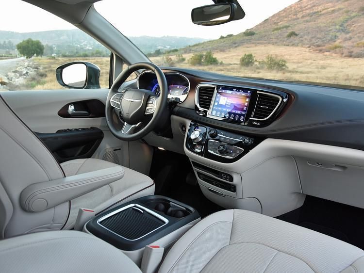
TO OUR VALUED CUSTOMER

It is our intention to provide our valued customers with the best documentation possible to ensure successful use of our
products. We will continue to improve our publications to better suit your needs. Our publications will be refined and
enhanced, as new volumes and updates introduced. If you have any questions or comments regarding this publication,
please contact us.
We welcome your feedback.

CUSTOMER CARE CENTER

For additional application assistance, we urge you to consult with our experienced staff in our Customer Care Center. Our
Technical and Engineering staff has extensive test, research and development capabilities, and have assisted many
customers in solving unique design and application problems with standard or customized products.

                  R&D Contact Address                                      US Support Contact Address

                                                                                  Clock Mobility
                                                                                 6700 Clay Ave. SW
                   R.A.SH Tronics Ltd
                                                                               Grand Rapids, MI 49548
                 rashtronix@gmail.com
                                                                                   (616) 698-9400
                                                                           technicians@clockmobility.com

ABSTRACT

This guide explains how to install the modules in the vehicle.

    v The information provided in the wiring diagrams is vehicle specific. It should be applied only to the vehicle
      indicated. Depending on the system you are installing, you may not install every harness.
    v Read modules placement first, it is very important to understand were to connect and fit the CAN-Bus based
      components to avoid future problems.
    v This manual becomes an integral part of the vehicle the system-installed in. You should therefore always keep
      it in the vehicle and pass on to the new owner, to safely use the systems.
    v R.A.SH Tronics Ltd reserve the right to make changes in product specifications at any time and without prior
      notice. The information in this manual, believed to be accurate and reliable. However, R.A.SH Tronics Ltd assume
      no responsibility for its use.

USEFUL HINTS

         v The electronic control board is an electrostatic sensitive device. Connect to a proper ground.
         v Use care when making electrical connections. Disconnect battery power prior to servicing.
         v When installing, check for any obstructions such as Gas tank, Gas lines, Wires, etc. before drilling or routing
           power cable.
         v For continued protection against fire hazard, replace only with the same type and rating of fuse.
         v Only allow R.A.SH Tronics factory trained technicians to install or service your system. If wear is observed
           on any part in the system, contact our US support.

                                                                                                                         3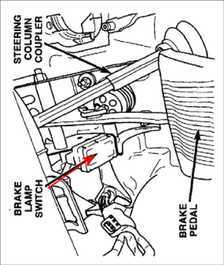
SECONDARY CONTROLS DEFENITIONS

Secondary controls are any devices that accept a control input from a driver for the purpose of operating the sub systems
of the motor vehicle, other than those associated with the primaries.
Secondary Control list of functions:
    1.    Secondary control panels
               a. LCD touch panels
               b. Momentary/ Toggle switches
               c. Voice scan systems
    2.    Transmission
               a. Powered gear selector (Vehicles using power cable for direct control of the gear box)
               b. CANbus gear selector (Vehicles using electronic control unit for shifting)
    3.    Ignition and Engine start
    4.    Parking Brake
    5.    Turn signals with automatic cancelling function
               a. Canceling systems using CANbus steering position
               b. Timers controlled by the stop light switch
               c. Magnets under the steering for position detection
    6.    Hazard Warning Signals
    7.    Windshield Wiper/Washer
    8.    Lights
    9.    Horn
    10.   Seat Adjustment
    11.   Power Windows
    12.   Power Mirrors Adjust
    13.   Door Locks
    14.   Cruise Control
    15.   Heating, Ventilation and Air Conditioning Control (HVAC)

                                                                                                                        4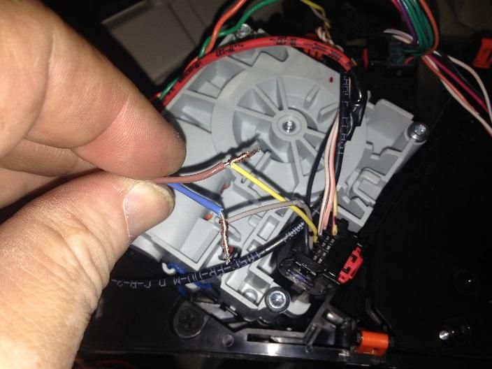
STEERING MODULE CANbus Supported functions : GEAR SELECTOR CANbus
Horn
TURN SIGNALS Supported functions :
F/R WIPERS WASHERS Gea r Selector
LOW/ HIGH BEAM/ FLASH Start Stop module
CRUISE CONTROL
1 6
SYSTEM BLOCK DIAGRAM
EGRESS/Docking and
1 4
many more functions
typeAA
BLU
BLU
BRN
BRN
GRN
GRN
ORG
Cabletype
ORG
Cable
COMPUTER DATA
LINES SYSTEM
COMPUTER DATA
LINES SYSTEM
SECONDARY FUNCTIONS MODULE
4 1 6 1
LIN junction box
P/N: STA-35-LJ
Electronic Park brake system
4
User input device 1
Voice scan system
Supported functions :
BLU
BRN
Windows Haza rd Warni ng Li ghts
A p p l i c a b l e V e h i c l e s:
Door locks Side & Head l ights
CHRYSLER PACIFICA 2016, UP
Sl iding doors
HVAC.
Ex. Mirrors
R.A.SH Tronics Ltd CHRYSLER PACIFICA, TOTALLY INTEGRATED SYSTEM OVERVIEW
(T) +972-48517656 Size CAGE Code DWG NO Rev
© 2018 R.A.SH Tronics Ltd. All rights res erved. Reproduction by any mea ns , electronic, graphics
(F) +972-48523339 A4 059-957-746 STA-35 A
(GUI) or mechanical, including photocopying, recording or by any information s torage a nd
retrieval s ys tem or tra ns lati on in whole or part is NOT PERMITTED without written a uthorizati on rashtronix@gmail.com
Scale Sheet
Monday, April 16, 2018 2 of 3
5
from R.A.SH Tronics Ltd IL.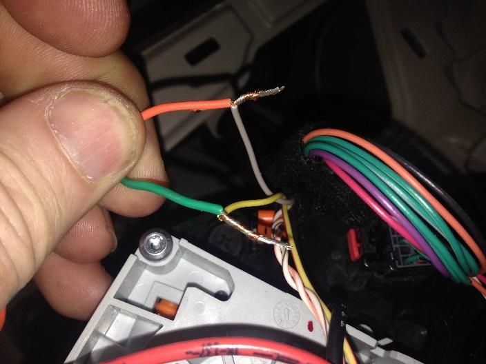
DESCRIPTION OF MAIN COMPONENTS

DRIVEIN STA-35-xxx DISPLAY

Through this 3.5” resistive touch screen displays you can control all
operation and programming functions for the DRIVEIN system.
All secondary functions are also controlled and programmed
Through the display. It’s location in the vehicle will vary,
depending on the system set-up and mounting options for the
driver. Most secondary functions can be remotely operated from
other devices (In motion voice scan, five buttons Round Touchpad,
five ways joystick and do it yourself switches), depending on the
customer needs. Refer to the Drivein
Operation and Programing Manual for further details.

VEHICLE INTERFACE MODULE

Through this dual CAN-Bus gateway module, which is connected to
the vehicle communication network, it is possible to control
almost all secondary functions like Driver/passenger window, turn
signals, horn and many more. It is connected to the OBD harness
and to another CAN-Bus harness in the vehicle.
It is also used to collect real time information and update the LCD
display.

CANbus GEAR SELECTOR & ENGINE START/STOP MODULE

This module is used to override the OEM start stop system, it is
designed to be directly attached to the OEM high current harness
using the quick-fit terminals of the OEM harness. No need to
solder just remove the OEM wires from the connector and plug
them as per wiring diagram provided in this manual for your
specific vehicle.

UNIVESAL 12 RELAYS MODULE

Can do many functions:
    1. Motor control
    2. Docking station
    3. EGRESS
    4. Lift’s and hoists
    5. Hazard warning lights

                                                                        6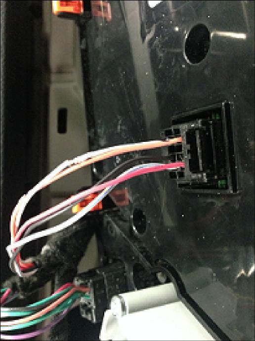
DESCRIPTION OF MAIN COMPONENTS CONTINUED

INPUT DEVICES: RID-1L round input device.

It has five buttons blue lighted with universal automotive
symbols. It should be mounted within reach of the driver.

It is designed to access the in-motion functions like turn
signals and horn.

Five big buttons easy to use, small size.

INPUT DEVICES: JID-1L joystick input device.

It is a five ways mini-joystick, very small size, easy to use
can be mounted within easy reach of the driver.

 It is designed to access the in-motion functions like turn
signals and horn.

INPUT DEVICES: DIY-1L twelve momentary switches input
device.

This module is used to access up to twelve functions in the
vehicle using low effort switches. Can be mounted under
the steering and hardwired to different switches located
within easy reach of the driver.

INPUT DEVICES: GID-1L round input device.

It has five buttons blue lighted with universal automotive
symbols. It should be mounted within reach of the driver.

It is designed to control the start stop function and gear
control.

Five big buttons easy to use, small size.

                                                                7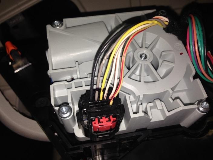
CAN-BUS GATEWAY MODULE

The R.A.SH Tronics CANbus gateway is a very powerful device, it allows access for many of the vehicle functions without
the need to remove plastic parts or additional external relays. The CANbus gateway interface with the OEM CAN system
in order to operate most of the secondary functions.
The CAN Gateway Module connects to the Drivein LCD touch screen on the LIN junction port and to the vehicle’s CAN
system to operate the secondary functions, listed below in the table. It is also responsible to wake up the touch screen
and put to sleep after locking the vehicle.
THESE SECONDARY FUNCTIONS WILL REQUIRE NO FURTHER PHYSICAL WIRING, which will greatly reduce the amount
of installation time and increase reliability. There are, however, a few secondary functions that will require physical
wiring. These functions are not listed in the table below but in the pages to follow. The CAN Gateway module is connected
to the vehicle’s OBD connector located on the lower left dash panel in the driver’s area and to the low speed CAN
simultaneously. The Gateway module itself is typically installed behind the center console area and secured to vehicle
using the mounting tabs on the module. The CAN Gateway Module is responsible to wake up and put to sleep of all
system components, so be sure to connect the wires utilizing proper soldering practices according to SAE J1292.

 FUNCTIONS CONTROLED THROUGH CAN-Bus (NO PHYSICAL WIRING REQUIRED)
                                                                   HVAC (Heating ventilation and air conditioning)
 Windows Up & Down
                                                                      · Fan speed, 7 steps.
    1. Driver
                                                                               o Fast
    2. Passenger
                                                                               o Slow
 Door lock/Unlock
                                                                               o Off
 The system knows the current door status and behaves
 accordingly.                                                         · Air flow five positions
 Exterior mirrors Up/ Down, Left/ Right                                        o Front
     1. Driver                                                                 o Floor
     2. Passenger                                                              o Front & Floor
                                                                               o Floor & Defrost
 Sliding Doors Open/ Close                                                     o Defrost
      1. Driver                                                       · A/C
      2. Passenger                                                             o On/ Off
                                                                               o Auto
                        Steering Functions
                                                                      · SYNC
 Horn (This function uses relay inside the CAN module)                · Temp (full range)
                                                                               o Hot
 Turn signals.                                                                 o Cold
 Automatic cancelation implemented using the CANbus
 steering position information.                                    Important notes:
 Front wipers                                                         · Optional to control the Rear HVAC
 Important: Our system does not cancel the Auto wipers function.      · The system does not cancel any OEM function.
                                                                      · HVAC functions are usable from OEM and our
      1.   Intermittent wipe              3.   Rapid wipe
                                                                           system in parallel.
      2.   Normal wipe                    4.   Front wash

                                                                   Cruise control
 Rear Wipers
                                                                       1. Automatically turned On
     1. Intermittent wipe
                                                                       2. Set/ Decelerate
     2. Normal wipe
                                                                       3. Resume/ Accelerate
     3. Rear Wash
                                                                       4. Cancels by foot brake

                                                                                                                        8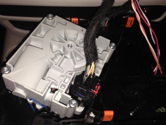
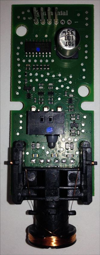
CAN-BUS POWERED GEAR SELECTOR MODULE

This new R.A.SH Electronics powered gear selector uses the CAN-Bus network information to function, it makes it easy to
fit inside any modern vehicle. Since the CAN-Bus information
is very reliable, shifting do not rely on Potentiometer position
or the voltage measured out of it and do not rely on untrained
programmer. Check wiring diagrams below.
The Chrysler Pacifica new concept of powered gear selector,
brings the vehicle safety to a higher level, due to the fact that
the system collects the vehicle speed combined with the foot
brake information, makes it easy to operate the system by
pressing the gear buttons shortly, not using the Long/ Short
press mode, once Reverse button is pressed while the
vehicle is driving in a high speed, even if the foot brake is
slightly pressed, no shifting is possible. Another important
feature is that this vehicle has no gear cable going to the gear
box, it is purely based on CANbus (Picture A/ B), our gear
selector module is a CANbus gateway that is integrated into
the Pacifica communication network as any OEM module so the manufacturer diagnostic tools cannot recognize it and
cannot recognize the OEM CANbus wires are cut, Picture C/ D.

                         Picture A                                                  Picture B

                         Picture C                                                  Picture D

                                                                                                                      9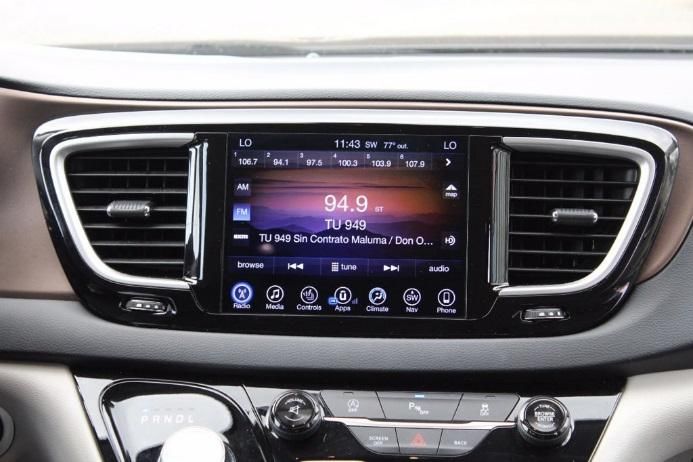
IDENTIFYING GEAR SELECTOR SWITCH
GRY
GRY
RED BLU
BLK WHT/BLU
WHT
J1 8 7 6 5
F1 4 3 2 1
Control board bottom side 4
5A FUSE
MDL: shorted
Wires for start stop system
1
ECU: open
CANBUS GATEWAY WIRING
Cut location is about 2" from
ECU CAN-Bus
MDL CAN-bus
OEM connector.
BLU
GREY (CAN_H)
BRN
GRN
GRY #9
ORG
YEL (CAN_L) YEL #8
BLK (GND) BLK #10
COMPUTER DATA
LINES SYSTEM
YEL/RED (BAT) YEL/ RED # 1
6
1
TB1 Front
5
Terminal Block
10
GND IDENTIFYING GEAR SELCTOR MODULE
Sw 3 (ON CENTER CONSOL)
Supported input devices
Park Position
GID-1L
Sw 4
STA-35-xxxx
Gear selector touch buttons R/N Position
Sw 5
D Position
Ap p l i c a b l e V e h i c l e s:
R.A.SH Tronics Ltd CHRYSLER PACIFICA, CAN-bus Gear Selector
FIAT PACIFICA
(T) +972-48517656 Size CAGE Code DWG NO Rev
© 2018 R.A.SH Tronics Ltd. Al l ri ghts res erved. Reproducti on by any means , electronic, (F) +972-48523339 A4 059-957-746 RSM-50-xxx A
gra phi cs (GUI) or mechanical, i ncluding photocopying, recording or by any i nforma tion
rashtronix@gmail.com
s torage and retrieva l s ys tem or trans lation in whole or part is NOT PERMITTED without Scale Sheet
Tuesday, April 10, 2018 SW: RSM-50-CPCF.hex 2 of 3
wri tten authorization from R.A.SH Troni cs Ltd IL.
10PUSHBUTTON START MODULE
The SS-1L-CPCF start stop system is linked to the LCD touch system and it is part of the CANbus gear selector, meaning
there is no additional module to install; the system is constantly updated with the
vehicle status through the CANbus network. This module should be mounted in an
easy to reach under the steering area. The systems supplied with 600mm (24”)
harness, it is not recommended to extend the wires especially the CANbus wires.
Only one OEM cable should be cut and wired to the system harness, all the rest are
tapped into the OEM, all wires MUST be soldered, do not use any other way to tap
into.
USING THE START STOP FUNCTION
Depending on your input device whether it is a GID-1L or LCD touch, the start stop funtion behaves exactly the same, the
description below describe using the LCD touch input device for starting and stopping. The system supports two way
starting options, the first is to shortly press to activate the ignition and then press and hold to start; the second is to press
and hold until engine started, eather way, no need to press the foot brake.
1. When the vehicle is stationary and the ignition is Off:
a. Shortly press the animation key Figure A to turn on the ACC.
b. Shortly press a second time to turn on the ignition.
2. When the vehicle is stationary and the ignition is On:
a. Shortly press the key symbol to turn off the ignition.
b. Press and hold the key until the engine started, the symbol changes Figure B indicating engine running.
3. When the vehicle is stationary and the ignition is Off:
a. Press and hold the animation key Figure A until the engine started and indicated by Figure B.
Important:
· When the vehicle is driving (in move) it is not possible to stop the engine when the key symbols is pressed
either long or short. Use the OEM engine start stop switch.
· This modification does not cancel any OEM function, it can be used in parralle, will not cause any error.
MODIFYING THE ENGINE START STOP MODULE
Follow the instructions below to succesfully modify the OEM start stop module, it should be carefully removed, there are
only two wires to solder on board as can be seen in the wiring diagram.
We accept no resonsibility for any damadge you cause to the OEM board, disconnect the module from power and then
comence the modification and double check everything before you drill or solder or remove plastic parts.
The manufacturer used two similar wire colors in the foot brake connector (Dark Green with Brown strip), one of them
when measured using a digital volt meeter, must show voltage level below 0.5V, this is the wire that should be cut as can
be see in the wiring, the second wire should show voltage level abouve 2.0V, do not cut this wire.
11IDENTIFYING THE ENGIEN START
ENGINE START STOP INSIDE STOP SWITCH (ON RIGHT SIDE OF
BOARD VIEW STEERING)
ENGINE START STOP WIRING
IDENFIFYING THE BRAKE LAMP
SWITCH (TOP OF BRAKE PEDAL
ASSEMBLY)
GRY
GRY
WHT/BLU (30)
WHT (87A)
BLU (87)
R1 150R DK GRN/YEL #3 (PWR +5V)
5 DK GRN/BRN #2 (SIG)
Suppl i ed
1 wi th the ki t DK GRN/BRN #1 (GND)
GND
CANbus GEAR SELECTOR
MODULE
R.A.SH Tronics Ltd CHRYSLER PACIFICA 2017, PUSHBUTTON START WIRING
© 2018 R.A.SH Troni cs Ltd. Al l ri ghts res erved. Reproducti on by a ny means , el ectroni c, gra phi cs (T) +972-48517656 Size CAGE Code DWG NO Rev
(GUI) or mecha ni ca l , i ncl udi ng photocopyi ng, recordi ng or by a ny i nforma ti on s torage and (F) +972-48523339 A4 059-957-746 RSM-50-CPCF A
retri eva l s ys tem or tra ns l ati on i n whol e or pa rt i s NOT PERMITTED wi thout wri tten rashtronix@gmail.com
a uthori za ti on from R.A.SH Troni cs Ltd IL. Scale Sheet
Sunday, April 08, 2018 2 of 3
12Control board bottom side
RED MDL: shorted
GRY
ECU: open
Sw5
Sw4
Sw3
Sw2
Sw1
Com. (-)
TB1
Sw. Com. (-)
BLK
Terminal Block GRY
GND
J1: Horn select
SW1
(CANbus or Relay) Ds1 8 7 6 5
J1
Left Indicators F1 4 3 2 1
J1 J2 5A FUSE VAC-12LCC
SW2
J3 J4
MULTI-FUNCTION MODULE
Settings Right Indiators
SW3
Horn
SW4
High beam
SW5
Cut location is about 3" from
Wipe/Wash OEM connector.
BLU
BLU/WHT (CAN_H)
BRN
GRN
ORG
YEL (CAN_L)
STA-35 LCD touch RID-1L JID-1L DK GRN/PPL (Horn)
COMPUTER DATA
LINES SYSTEM
BLK (GND)
RED (BAT)
Supported Functions STEERING COLUMN CONTROL MODULE
(TOP OF STEERING COLUMN)
Horn
Turn Signals (CANbus s teeri ng pos ition ca ncel ati on)
Low/ Hi gh beam & Fl as h to pas s
A p p l i c a b l e V e h i c l e s:
Wi pers : Int/ Norm/ Rapi d & Was h
CHRYSLER PACIFICA DODGE JOURNEY 2014
Crui s e Control: On/ Set/ Accelerate/ Decelera te
JEEP GRAND CHEROOKEE
CHRYSLER 300C
R.A.SH Tronics Ltd CHRYSLER PACIFICA, CAN-bus multifunction
© 2018 R.A.SH Tronics Ltd. All rights res erved. Reproduction by a ny mea ns , electronic, (T) +972-48517656 Size CAGE Code DWG NO Rev
graphics (GUI) or mecha ni ca l, incl uding photocopyi ng, recording or by a ny informa tion (F) +972-48523339 A4 059-957-746 RSM-50-xxx A
s torage and retri eval s ys tem or trans lation in whol e or pa rt i s NOT PERMITTED without rashtronix@gmail.com
written authoriza tion from R.A.SH Troni cs Ltd IL. Scale Sheet
Monday, April 16, 2018 SW: VAC-12LCC-CPCF.hex 2 of 3
13El ectroni c Pa rk Bra ke
Swi tch connector
WHT/BRN (SIGNAL)
BLK (GND)
SECONDARIES MODULE
R1 R1 i s s uppl i ed
1k wi th the ki t
AC MODULE (ON CENTER CONSOL)
F1 RED (BAT)
WHT/BLU (30)
BLU (87)
WHT (87A)
5A FUSE GRY
4
BLK (GND)
GRY 1
LIN junction box P/N: STA-35-LJ
WHT/ BLU (HZ) 8 7 6 5
4 3 2 1
4
8
SUPPORTED FUNCTIONS
BLK (GND) HVAC
1
5
Dri ver & Pa s s enger wi ndows
Dri ver and Pa s s enger power mi rrors
Dri ver & Pa s s enger s l i di ng doors
Centra l l ocki ng
GRN
ORG
Ha za rd l i ghts
WHT (CANL)
Si de and Head l i ghts
ORG (CANH)
MDL ECU R.A.SH Tronics Ltd CHRYSLER PACIFICA, SECONDARY FUNCTIONS MODULE
© 2018 R.A.SH Troni cs Ltd. Al l ri ghts res erved. Reproducti on by a ny mea ns , el ectroni c, (T) +972-48517656 Size CAGE Code DWG NO Rev
gra phi cs (GUI) or mechani cal , i ncl udi ng photocopyi ng, recordi ng or by a ny i nformati on (F) +972-48523339 A4 059-957-746 VAC-12LCC-CPSEC A
s torage and retri eval s ys tem or tra ns l a ti on i n whol e or pa rt i s NOT PERMITTED wi thout rashtronix@gmail.com
wri tten a uthori zati on from R.A.SH Troni cs Ltd IL. Scale Sheet
Wednesday, August 08, 2018 SW: VAC-12LCC-CPCF.hex 2 of 3
14USING THE HEADLIGHTS
The headlights function supported by the module, once turned on it is not possible to turn it back off using the touch
button, only with the ignition turned off.
1. Turn on the ignition.
2. Press and hold the Lights symbol on the multi-function screen until the head lights turned on.
3. Switch off the ignition to cancel the head lights.
USING THE HAZRD WARNING LIGHTS
The hazard lights are functional at any time. This function once triggered it stays active regardless of the ignition switch
condition. To cancel the hazard warning lights, the driver must press the same touch button.
1. Wake up the vehicle by touching any switch in your vehile.
2. Select the hazard symbol on the second screen of the multifuntion panel, it is the red touh button.
3. Shorlty press the hazard touch button to activate the hazards lights.
4. Shortly press a second time to cancel.
15IDENTIFYING THE ELECTRONIC PARK SWITCH
PARK BRAKE WIRING
RELAY
87
30
87a 1 3 4
U1 6
7 12
11
DK GRN (#1 Si g 1)
Ba ck vi ew
DK GRN/GRY (#3 Si g 2)
DK GRN/GRN (#4 Si g 4)
DK GRN/BLU (#11 Si g 3)
us e gear s el ector & s ta rt s top modul e
R.A.SH Tronics Ltd CHRYSLER PACIFICA, ELECTRONIC PARK BRAKE WIRING
© 2018 R.A.SH Troni cs Ltd. Al l ri ghts res erved. Reproducti on by a ny mea ns , el ectroni c, gra phics (T) +972-48517656 Size CAGE Code DWG NO Rev
(GUI) or mechani ca l , i ncl udi ng photocopyi ng, recordi ng or by a ny i nforma ti on s torage a nd (F) +972-48523339 A4 059-957-746 A
VAC-12LCC-CPSEC
retri eva l s ys tem or tra ns l a ti on i n whol e or pa rt i s NOT PERMITTED wi thout wri tten rashtronix@gmail.com
a uthori za ti on from R.A.SH Troni cs Ltd IL. Scale Sheet
Friday, May 11, 2018 2 of 3
16In Motion box P/N: IMID-1L
LCD connector
VOICE SCAN WIRING
1
4
Volume increase
4
Volume decrease
Extended function
1 select
Extended function select
Short press: Play music
Volume decrease
Five ways joystick
DIY Sw itch
Green (20AWG) Sw itch
Volume increase
F1 SW PUSHBUTTON
Green (20AWG) Com.
RED RED (20AWG)
J1-6 BAT/ IGN
The switch is not supplyed. Add
The red wire can be powered by 5A FUSE momentary switch if not used with
BAT or switch supply IGN. 6 5 4 J1 Female the Joystick.
3 2 1
Pow er
BLACK (20AWG)
J1-3 GND
SPEAKER (-)
Speaker supplyed as part of the system.
So no need to add spearer.
SPEAKER (+)
R.A.SH Tronics Ltd IN MOTION, INTELLIGENT VOICE SCAN SYSTEM
© 2017 R.A.SH Tronics Ltd. All rights reserved. Reproduction by any means, electronic, (T) +972-48517656 Size CAGE Code DWG NO Rev
graphics (GUI) or mechanical, including photocopying, recording or by any information (F) +972-48523339 A4 059-957-746 IMID-1L A
storage and retrieval system or translation in whole or part is NOT PERMITTED without rashtronix@gmail.com
Scale Sheet
written authorization from R.A.SH Tronics Ltd IL. Wednesday, September 20, 2017 1 of 1
17USING THE HVAC
The HVAC module is very smart, it can control almost all funtions of the driver side only. Some touch buttons can do
two or more functions, please read the instructions and practice yourself before driving.
This is the multifunction control touch button: repeadetdly to toggle through the
settings and manually choose one of the following air distribution modes (Panel, Floor,
Panel and Floor,Floor and Defrost).
to select the SYNC mode, this mode is used to select singel or dual zone.
This touch button can do three functions:
Shortly press to decreas the fan speed one step.
Press and hold to constantly decrease the fan speed until button released. If the button
continue to be depressed for more than 2 seconds, the HVAC will be turned off.
Shortly press this touch button to turn on the HVAC and increase the fan speed one step.
Press and hold to constantly increase the fan speed until the button released of the
maximm speed reached.
touch to activate/deactivate to engage full automatic operation
airconditioning
Shortly press this touch button increase (Hot) the tempereture one step.
Press and hold to constantly increase the temperature until the button released or the
maximm temperature reached.
Shortly press this touch button decrease (Cold) the tempereture one step.
Press and hold to constantly decrease the temperature until the button released or the
maximm temperature reached.
18USING THE CRUISE CONTROL
19APPENDIX
SPECIFICATIONS
The following chart lists the standard wire colors and their corresponding abbreviations that will be used for the
installation of all R.A.SH Tronics Ltd products.
WIRE COLOR COLOR ABBREVIATION WIRE GAUGES CURRENT RATING
BLACK BLK 0.3mm AWG22 5A
BROWN BRN 0.5mm AWG20 7A- 13A
RED RED 0.85 mm AWG18 9A-17A
ORANGE ORG 1.28 mm AWG16 12A-22A
YELLOW YEL 2 mm AWG14 16A-30A
VIOLET VLT 3 mm AWG12 21A-40A
GRAY GRY
WHITE WHT
TAN TAN
PINK PNK
PURPLE PPL
BLUE BLU
LIGHT BLUE LT BLU
DARK BLUE DK BLU
GREEN GRN
LIGHT GREEN LT GRN
DARG GREEN DK GRN
SOLDERING SPECIFICATION
Soldering Method- The soldering method shown at
right is offered for general information. Depending on
the connection desired, other methods may be used.
20You can also read