APT-06 / APT-06 AD Weather Satellite Receiver
←
→
Page content transcription
If your browser does not render page correctly, please read the page content below
Weather Satellite Receiver
          APT-06 / APT-06 AD
            Operating Manual

WRAASE electronic
WeSaCom-Systems
Kronsberg 10
24161 Altenholz
Tel. 0431 32528
Fax 0431 32579
www.wesacom.de
E-mail: info@wesacom.de

Manual APT-06 / APT-06AD. Prices and specifications are subject to change without notice.   1
 All rights reserved. © WRAASE electronic 2008-2013
Weather Satellite Receivers APT-06 / APT-06AD
Introduction and Leading Particulars

The APT-06 was especially designed to receive Polar Orbiter Weather Satellites
in the 137 MHz VHF frequency range. It feeds the received, demodulated and
filtered satellite image data into the sound input of a PC or laptop computer for
further processing. In conjunction with special decoding and image display
software an automatically operating weather satellite image reception station can
be set up. „WX-to-Image“ is the ultimate software for this. It controls the APT-06
for fully unattended and automatic operation.

Besides automatic operation, the APT-06 also offers manual control capability,
which is helpful especially during setup and for experiments. Furthermore the
APT-06 package comprises the Windows software program „APT-CONTROL“,
which can be operated in a separate window besides the image decoding
program. It allows detailed frequency- and other remote control functions on the
APT-06.

An exactly matched receiver IF bandwidth of +/- 16 kHz together with an
extremely linear demodulator guarantees the superior image quality and precise
temperature calibration WRAASE / WeSaCom Systems are well known for.

  Satellite frequency Doppler shift is precisely compensated by a special AFC-
circuit, which is fully active already when the satellite comes up over the horizon.
This eliminates noisy reception periods when the satellite is quickly approaching
from long distance. In addition, an active filter circuit carefully matched to the
satellite subcarrier frequency is implemented to reduce remaining noise
components. A carefully designed, precise phase-locked-loop circuit with a
special integrated circuit is used to demodulate and extract the satellite
subcarrier. Due to the excellent linearity and the much lower noise it is the best
available choice for picture generation. The result is a clearer image and a wider
range of reception.

In the front-end, high-quality Hi-Q-filters with shielded helical coils provide a very
high immunity against interference from strong signals in the close-by aviation
and ham radio bands.

Due to the low noise figure (typical 1dB) of the built-in rf-amplifier an additional
antenna amplifier is not necessary. However, when a long antenna feed must
be used, an antenna preamplifier or an active antenna is advantageous because
it compensates for the cable loss and thus increases the reception range. When
using a WRAASE active antenna additional interference immunity is achieved
due to strong Hi-Q-filtering. DC supply for the active antenna or the preamplifier
is provided through the APT-06 antenna socket(s) by simple insertion of a
jumper plug on the rear panel.

Manual APT-06 / APT-06AD. Prices and specifications are subject to change without notice.   2
 All rights reserved. © WRAASE electronic 2008-2013
At any time signal quality can be monitored by the built-in switchable speaker.
Undisturbed by any other signals, the built-in frequency scanner reliably locks
only to weather satellites. It looks for the special weather satellite subcarrier
frequency and will not hang on other signals like simple scanners do. Once a
satellite has been found, the APT-06 locks on its frequency as long as it is in the
range of reception even if there are signal drop outs. The lock-in routine can be
manually released at any time, which might be necessary if at the same time
several satellites are in the range of reception and the scanner has locked on an
unwanted one. Such ambiguity can be avoided when having the APT-06
frequency being controlled by the PC software. The “WX-to-Image” software
provides such capability and it controls the APT-06 so that the proper channel is
automatically selected for the next satellite to be recorded.

Such computer control is fully supported by the built-in USB-interface and
connector, however due to the smart scanning technology it is not mandatory.

The row of five LEDs are not only used for channel indication, they can also act
as 5-step signal-quality meter. Instead of simply showing the relative signal
strength, the processor continuously computes and indicates the signal-to-
noise-ratio, which is much more meaningful when receiving frequency
modulated signals with image information.

In addition, the advanced model APT-06AD contains an Antenna Diversity
Circuit, which under difficult reception conditions provides means to effectively
reduce signal drop-outs and noisy image sections. Such signal losses are in most
cases caused by reflections, which result in several waves arriving at the antenna
in different phase angles. Antenna-diversity uses the fact that when two antennas
are used at slightly different locations, both antennas receive the waves in
different phase conditions and it is therefore very unlikely that a minimum occurs
at both antennas in the same moment. Continuously monitoring the signal and
quickly switching between two antennas can eliminate drop outs and achieves
nearly continuous reception quality.

The APT-06AD uses the signal-to-noise value as switching criterion: A fast
microprocessor continuously analyzes the signal-to-noise ratio and selects the
less noisy antenna. Such antenna diversity based on noise evaluation is much
more efficient than simple signal strength based circuits.

Considering its outstanding receiving capabilities, the APT-06AD offers a very
high price/performance value.

Manual APT-06 / APT-06AD. Prices and specifications are subject to change without notice.   3
 All rights reserved. © WRAASE electronic 2008-2013
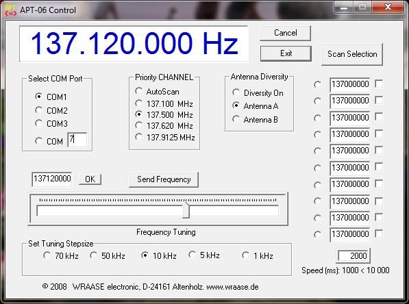
Making the Connections & Operating the APT-06 / APT-06AD

The unit is powered from USB, no external power is required. However, external
power supply is possible (from 9-12V DC battery at 100mA or AC power supply).
This can be desired, when satellite signals are to be checked through the
speaker and/or level indication without the computer being connected or running.
For example during antenna installation when trying to find the best position.
Also, when using high-power USB devices, like external hard-drives, the
maximum USB power can the reached quickly and it may be desirable to run the
receiver independently from USB power in order to avoid automatic shut-down.

USB power is automatically disconnected when a DC power connector is plugged
into the “DC” socket on the rear panel of the APT-06.
Connection of external DC in the wrong polarity will activate the built-in security
circuit which disconnects power by a thermal fuse. Immediately remove the
wrong polarization! After a short waiting time and as soon as the fuse has cooled
down, the APT-06 should work normally.

 The APT-06 has no power on-off switch. As soon as power is plugged in, it will
power up and the 5 red LEDs start blinking all together for about 5 seconds.

Only applicable for the model APT-06AD: You can activate the antenna
diversity circuit by pressing the push-button (=>) once during the 5 seconds
blinking period just after power-up. If you don’t press the button during the
blinking period, antenna diversity is not active and you can only activate it by a
reset (unplug power/USB and plug it in again) or by means of the program “APT-
CONTROL”. Operation of the antenna diversity circuit is indicated by the green
LED, which informs the user which antenna is currently switched on. When no
signal is received, it will be blinking (switching between antennas continuously).
If antenna diversity is not activated, only antenna input “A” is active and the
green LED will light when a satellite signal is being received.

Antenna Connection

It is strongly recommended to use a special weather satellite antenna with right-
hand circular polarization (KX-137 or MX-137). Only with such antennas an
Manual APT-06 / APT-06AD. Prices and specifications are subject to change without notice.   4
 All rights reserved. © WRAASE electronic 2008-2013
interruption-free satellite pass and a coverage range of 4000 or more kilometers
can be expected. If the antenna cable length is in the range of 20 to 30 m, an
antenna preamplifier may not be necessary. Our preamplifier AA-137 or the
active antennas KX-137 or MX-137, however, will in most cases improve
reception-quality and -range as well as immunity against strong terrestrial signals
because of the integrated high-Q-filters and the extremely low-noise transistors.

With our preamplifier AA-137 or an active antenna the standard RG-58U coaxial
cable can be used without problems: Higher cable attenuation and / or slightly
improper matching are fully compensated by the preamplifier.

In order to dc-supply a preamplifier or an active antenna without the need of an
additional cable, DC-voltage of 9 V is provided on the antenna input socket (if
the jumper is inserted at the rear panel). Many passive antenna constructions
represent a DC-short-circuit which would cause an immediate fuse-blow inside
the APT-06 receiver. To avoid such a problem with passive antennas, it is
strongly recommended to disconnect the DC antenna supply by simply removing
the „ANT-DC“ marked jumper on the rear panel. Whenever a passive antenna
and no preamp is used, the jumper should be removed.

Antenna Considerations

As the satellites circulate in a polar orbit, the antenna should have a free line-of-
sight at least to north and south. Mounting the antenna under the roof is not
recommended (although in some cases acceptable results are achieved). The
height above ground is only critical with respect to the lowest possible line-of-
sight elevation angle to the horizon and possible reduction of the shadowing
effect of surrounding buildings. As a rule of thumb a line of sight to the horizon at
an elevation angle of 10 to 15 degrees is sufficient. This only applies for
buildings, trees are not so critical.
For good reception performance it is extremely important that the antenna is
mounted in a safe distance to any possible radiation sources of broadband radio
noise. Such sources of interference are computers and all devices which contain
microprocessors or switching power supplies. The broad noise floor created by
such devices (nowadays most electrical household equipment is suspicious) can
easily cover the weak satellite signal. Noise reduction regulations keep such
noise low but do not eliminate it in a close distance. Keeping the antenna in a
distance of several meters from such devices will normally avoid such
interference problems.

Connection to the PC

Received satellite data are output through the „SOUND“ marked rear panel
socket. Use the supplied standard cable to connect this socket with the sound
input of your computer, preferably the „LINE-IN“ socket.

Manual APT-06 / APT-06AD. Prices and specifications are subject to change without notice.   5
 All rights reserved. © WRAASE electronic 2008-2013
If external power is used: In order to avoid power line hum interference (gray
lines in the pictures) the PC and the receiver should be connected to the same
power line outlet.

OPERATION

Software Set-up

The APT-06 receiver works with any soundcard-based weather satellite reception
software so that the user can chose among different programs available on the
market. We recommend the program „WX-to-Image“ which delivers perfect
results even in the freeware version and allows to add professional features at
very moderate cost when being upgraded via the internet. The freeware version
already offers all major functions and supports automatic computer controlled
frequency selection of the APT-06.

Read the software instructions which contain all the necessary information for
proper installation and software setup. Most important for good results is the first-
time setting of the correct audio level. There are two controls with basically the
same effect: First the Windows Mixer Control and second the APT-06 hardware
control which can be reached through the hole in the front panel (use small
screwdriver). In the “WX-to-Image” program window there is a level meter in the
right bottom corner which should show green color (50 to 80 %) when receiving a
signal (FILE / RECORD / MANUAL TEST). You must find the correct level either
by modifying the setting of the Windows Mixer, the APT-06 level control or both.

Receiving Operations

After power-up the receiver will start in the scanning mode. The 5 fixed frequency
channels are assigned as follows (from left to right):

       Channel Indicator Function                     Signal Quality Indicator Function
    (1) 137.100 MHz NOAA19                          (1) 10%                  20 dB S/N
    (2) 137.400 MHz -.-                             (2) 20%                  25 dB S/N
    (3) 137.500 MHz NOAA17                          (3) 45%                  30 dB S/N
    (4) 137.620 MHz NOAA15                          (4) 70 %                 33 dB S/N
    (5) 137.9125MHz NOAA18                          (5) 100%                 > 35 dB S/N

At present time all available satellites are covered by these frequency channels.
Further channels may be added with a future firmware update. As soon as a
satellite appears on one of the channels, scanning will stop and resume a few
seconds after the satellite signal has permanently disappeared.

Manual APT-06 / APT-06AD. Prices and specifications are subject to change without notice.   6
 All rights reserved. © WRAASE electronic 2008-2013
To stop scanning and to activate manual mode, press the push-button (=>) once. Every further hit of the button will advance the channel. To reactivate scanning, press and hold the button and as soon as all 5 LEDs light, release it. In manual mode, the row of 5 red LEDs will also act as level meter. This function is activated automatically 10 seconds after the last operation of the “=>”-button and it remains active until the “=>” button is pressed again. Note that the level meter is only available in manual mode, not in scan-mode or PC-mode. The APT-06 weather satellite receiver operates completely automatically, no user intervention is needed: In the “Auto Record” mode of the “WX-to-Image” program the images will be recorded and processed according to the settings in the software. Images may be automatically uploaded to a website. You can at any time check the signal quality by pressing the „SP-ON“ push- button which activates the built-in loudspeaker. For further analysis of signal levels change into manual mode by pressing the => button until you have reached the desired channel and wait 10 seconds: The signal meter function starts and shows the signal quality according to above table. To return to channel indication, press “=>” again. APT-06 Computer Control Connect the APT-06 with the supplied USB cable to a free USB socket of your computer. Windows will recognize the interface and -if your computer has internet access- will install the required driver automatically through Windows Update. If this does not work, disconnect the APT-06 from USB and install the driver by running “CDM20828_Setup” from the supplied CD (in the USB directory). Then make the USB connection and watch the information window showing which COMPORT was created (the driver creates a virtual COMPORT). In “WX-to-Img” open the “Options / Recording Options“ menu. In the “receiver type” box select APT-06 and leave the baudrate setting with “receiver default”. In the “receiver port” box select the COMPORT your driver has created. If you are not sure about its number or want to change it, check in the Windows System Control. The driver on CD supports Windows XP, Windows Server 2003, Windows Vista, Windows Server 2008, Windows 7, Windows Server 2008 R2 and Windows 8 . Driver for other Operating Systems (Linux) can be directly obtained from the website of the manufacturer of the interface chip: www.Ftdichip.com/Drivers/VCP.htm. „WX-to-Image“ has a built-in satellite tracking module and automatically selects the correct channel for the next satellite to be received and sets the APT-06 to scanning mode after the image has been recorded. Manual APT-06 / APT-06AD. Prices and specifications are subject to change without notice. 7 All rights reserved. © WRAASE electronic 2008-2013
PC Control Software „APT-CONTROL“

The supplied software program APT-CONTROL offers additional comfortable
control functions and works under all Windows versions from Windows95 on. It
can be operated in a separate window parallel to the recording software. Keep in
mind, that the receiver can only be controlled by one program at a time and that
therefore “WX-to-Image” will not control the receiver as long as APT-CONTROL
is active.

APT-CONTROL does not require a special installation procedure. Just copy the
file APT_CONTROL.EXE to your computer and create a connection to the
Desktop. The USB cable connection should be made before you start the
program. If the cable connection has been interrupted while running the program
you must reestablish communication either by exiting and restarting the program
or clicking on your COM Port number in the “Select COM Port” box.
Windows has created a virtual Comport for the FTDI 232 interface chip in the
APT-06. To establish communication you must enter the Comport number in the
“Select Com Port” Editbox and activate it by checking the associated radio button
(Port 1 thru 3 can be activated directly). An error message will pop up if the
selected Comport is not active in your computer Operation of the program is
most self explanatory. After selection of the proper COMPORT try out the
settings in the „Priority CHANNEL“ section and check if the proper LEDs on the
APT-06 light.

APT-CONTROL offers several frequency selection options: While in the field
„Priority-Channel“ the fixed channels within the APT-06 firmware are selected,
the other frequency control options directly access the APT-06 digital synthesizer
Manual APT-06 / APT-06AD. Prices and specifications are subject to change without notice.   8
 All rights reserved. © WRAASE electronic 2008-2013
which allows arbitrary frequency selection in the range from 134 to 141 MHz
(note that full receiver performance is only guaranteed between 137 and 138
MHz).
First there are edit-boxes for direct numerical frequency input from the keyboard,
which require entry in Hertz ( 9 digits) and second there is a mouse or arrow-key
operated “Frequency Tuning” tool. Select the step-size of the slider in the field
“Set Tuning Stepsize”. To set the receiver APT-06 to the frequency being
selected and displayed in the large display field click the button “Send
Frequency”. To indicate reception of such external frequency commands the left
3 LEDs on the APT-06 will light.

In the right-hand field of the program window there is a vertical row of 10
frequency input boxes. These can be used to enter up to 10 preferred
frequencies. These values will be permanently stored on the computer so that
you don’t lose them when you exit APT-CONTROL. Clicking the radio button left
of the edit box will set the receiver to that frequency.
On the right-hand side of the frequency edit boxes there are check boxes, which
allow to create a selection of frequencies for scanning.
Scanning will be activated by clicking the button „Scan Selection“ and deactivated
by clicking it again. In the edit box “Speed (ms)” you can set the scanning speed
from 1 second to 10 seconds (must be entered in milliseconds). Any change of
speed requires a new start of scanning to come into effect. Upon reception of a
satellite the frequency will be locked and kept stable for undisturbed image
recording. APT-CONTROL continues sending the frequency commands to the
receiver; however these commands are neglected as long as the APT-06 has
locked to a satellite being in the range of reception.

The operations in the field “Antenna Diversity” apply to the model APT-06AD
only.
Here, the antenna diversity functions can be controlled independently from
selections previously made on the hardware.
“Diversity ON” activates the antenna diversity circuit.
“Antenna A” deactivates antenna diversity and selects antenna A.
“Antenna B” deactivates antenna diversity and selects antenna B.

When being in Antenna Diversity Mode, the green LED on the APT-06AD front
panel indicates which antenna is active: Green LED off = Antenna A is on; green
LED on = Antenna B is on. While no signal is received on both antennas the LED
is blinking, indicating that both antennas are continuously checked.
When Antenna Diversity is switched off, the function of the green LED changes, it
will light when a satellite signal is being received.

Safety Instructions
The APT-06 complies with the European Standards for Electromagnetic
Immunity and carries the CE sign. The weather satellites which the APT-06 is
designed to receive, transmit unencrypted data and can be received worldwide in

Manual APT-06 / APT-06AD. Prices and specifications are subject to change without notice.   9
 All rights reserved. © WRAASE electronic 2008-2013
equal quality. In Germany reception is generally permitted and free of charge. In
other countries other regulation may apply.
1. This appliance may only be used for the designated purpose. It may only
be used with grounded or isolated power supplies according to VDE
regulations.
2. This appliance is designated for use in rooms and a dry and dust free
environment at room temperature between +5° and +35° C.
3. It must be made sure that all wires and cables are carefully installed so
that nobody can stumble nor can be caught by them. Do never tear or twist
the cables.
4. Electrical appliances which are connected to the APT-06 like computers
must be properly grounded to avoid electrical shocks. Disconnect the unit
from power if it is not used for a longer period.
5. Keep any plastic bags used for packing from children and animals.
Technical Data, common for APT-06 and APT-06AD
USB controlled and powered, no external power required.
Can nevertheless run from external power, if desired.
Direct USB control without need to serial interface cable.
Fast microcontroller running at 22 MHz.
Frequency range: 137-138 MHz (134-141 MHz at reduced performance)
Channel step size: 10kHz
Fixed hardware-channels: 5 (by firmware extendable to 9)
Arbitrary channels, set by software: 10
Sensitivity: Better than 0,25µV @ 20dB S/N CCITT
AF-Output level: 0 to 1000mVpp (1k)
AFC-pulling range kHz
Smart scanning: Locks only to satellites even without computer control.
External Power connector: 9-12V, max. 100mA. Power from USB is
automatically disconnected when ext. power is plugged in.
Size: 105x105x30mm / 2mm thick aluminum case.
Operating controls: Channel /mode selection push-button,
Speaker-ON push-button.
5 red LEDs for channel, mode and signal level indication,
1 green LED for satellite signal available indication
and antenna diversity indication (APT-06AD only)
Antenna inputs(s): 50,BNC (APT-06AD has 2 of each)
USB connector, USB 1.0, 2.0 and 3.0 compatible.
Difference APT-06AD: Antenna Diversity, using a special, signal to noise
evaluation algorithm for fast antenna switching.
Manual APT-06 / APT-06AD. Prices and specifications are subject to change without notice. 1
All rights reserved. © WRAASE electronic 2008-2013You can also read