Megatorque Motors YSB Series - Significantly enhanced functionality at a low cost, absolute sensor to omit Homing as standard feature and freely ...
←
→
Page content transcription
If your browser does not render page correctly, please read the page content below
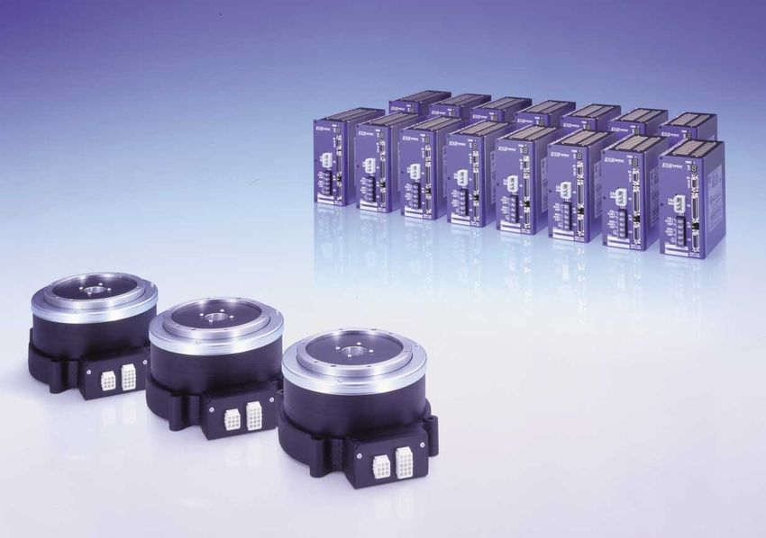
Megatorque Motors                          ®

YSB Series

Significantly enhanced functionality at a low cost,
absolute sensor to omit Homing as standard feature and
freely interchangeable motors and driver units to support
random matching.
High Performance & Low-Cost                                                                               YSB Series Megatorque Motors

    NSK, already recognized for introducing low-priced direct drive
    motors, has launched a new Megatorque Motor Series with enhanced
    functions whilst still maintaining a low cost.
    The YSB Series Megatorque Motor is suitable for a variety of industrial
    applications, including indexers in production equipment,
    semiconductor manufacturing and transportation equipment. Most
    notably, the Megatorque Motor has an absolute sensor to omit Homing
    as standard equipment. In addition, the Megatorque Motor makes the
    functional improvement of random matching of motors and driver units
    to cut down the number of assembling steps and production
    management costs, as well as many other features that combine to
    reduce costs while increasing production efficiency.
    NSK proudly introduces the YSB Series Megatorque Motor, providing
    customers with sophisticated functions at low prices.

                                                                                                                          C O N T E N T S
                                                                              Features of YSB Series Megatorque Motor               3,4       3.6.1 Features of ESB Model BC Driver Unit
                                                                              1. System Configuration                                              (CC-Link)                               15
                                                                                1.1 System Configuration                             5        3.6.2 CC-Link Specifications                 15
                                                                                1.2 Application                                      5        3.6.3 CC-Link System Configuration           16
                                                                                  1.2.1 Examples of Application                      6        3.6.4 CC-Link Interface                      16
                                                                              2. Megatorque Motor                                           3.7 Wiring Example                             17
                                                                                2.1 Configuration of Motor Reference Number          7    4. Cable Set
                                                                                2.2 Motor Specifications                             7      4.1 Configuration of Reference Number          18
                                                                                2.3 Dimensions of Motor                              8      4.2 Dimensions of Cable Set                    18
                                                                              3. ESB Type Driver Unit                                     5. Handy Terminal
                                                                                3.1 Configuration of Driver Unit Reference Number    9      5.1 Configuration of Reference Number          19
                                                                                3.2 Driver Unit Specifications                       9    6. Characteristics/Accuracy
                                                                                  3.2.1 Standard Model (ESB Model B3)                9      6.1 Speed/Output Torque                        19
                                                                                  3.2.2 Optional Functions                           9      6.2 Runout                                     20
                                                                                3.3 ESB Model B3 Driver Unit                        10    7. Selection
                                                                                  3.3.1 Input/Output Signal Specifications of               7.1 Estimation of Actual Load                  20
                                                                                       CN2 Connector                                10      7.2 How to Use Charts for Minimum
                                                                                3.4 ESB Model B5 Driver Unit (Option)               11          Positioning Time                           20
                                                                                  3.4.1 Input/Output Signal Specifications of             8. Combination
                                                                                       CN2 Connector                                11      8.1 Motors Equipped With Absolute
                                                                                  3.4.2 Input/Output Signal Specifications of                   Position Sensor                            21
                                                                                       CN5 Connector                                12    9. International Safety Regulations
                                                                                3.5 Electrical Specifications of CN2 and CN5                9.1 CE Marking                                 22
                                                                                    Connector                                       13      9.2 Underwriters’ Laboratory (UL)              22
                                                                                3.6 Field Bus Specifications (Option)               14

1                                                                                                                                                                                          2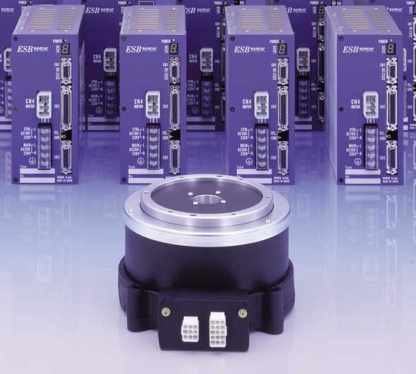
Features of YSB Series Megatorque Motor                                                                                                                                   YSB Series Megatorque Motors

    Point   1: Direct Drive                                    Point   4: Highly Functional Driver Unit
    The Megatorque Motor is capable to drive the load          The YSB Series Megatorque Motor constitutes a
    directly without using a mechanical speed reducer,         system in combination with an ESB Driver Unit for a                                                                                   Standard Feature
                                                                                                                          Homing
    and accordingly, it realizes highly accurate positioning
    without backlash and lost motion. A Megatorque
                                                               digital servo control incorporating a 32-bit
                                                               microprocessor.                                                                                                          Absolute Sensor
    Motor is a servomotor that equips a position detector      The ESB Driver Unit has a number of command inputs
    to form full closed loop control.                          necessary for motion control, thus permitting its                                 Current Series
                                                               connection with sequencers, a variety of positioning                                               Power off
    Point   2: High Accuracy                                   controllers and personal computers, etc. In addition,          Home position
    The YSB Series Megatorque Motor incorporates a             acceleration profiling and networking functions
    high-resolution position detector (resolver) that          through various field buses are available.
    features 819 200 pulses/revolution. This contributes to                                                                   Power off

    an exceptionally precise repeatability of ±1.6 arc         Point   5: Include Absolute Position Detector
    seconds.                                                              as Standard Equipment
                                                               The YSB Series Megatorque Motor has an absolute
    Point   3: High Reliability                                position detector as standard equipment. This                                                                            YSB Series

    The Megatorque Motor is a brushless motor and does         contributes to eliminate the troublesome Homing and
    not use permanent magnets in its simple construction.      thus improves productivity. Additionally, the motors
    It is equipped with a highly rigid and accurate roller     and the Driver Units can be randomly matched as a
    bearing (crossed roller bearing), which is packed with     pair. Cable can be freely selected up to lengths of 30m.                       No Homing Required
    lubrication grease, thus offering highly reliable and
    long-term maintenance-free operation.                      Point   6: Conformity to the International
                                                                          Safety Regulations
                                                               The Megatorque Motor systems conform to the EC
                                                               Directives (CE Marking) and Underwriters’ Laboratory
                                                               (UL) regulations.

    Random Matching of                                                                                                                         An Optional Function
    Motors and Driver Units
                                                                                                                                   Field Bus for Open Network

                                                                                                                                                                                                         Controller

                             YSB 2020
                            (YSB 3040)

                                                                                      ESB Model
                                                                                      B3 and B5

3                                                                                                                                                                                                                       4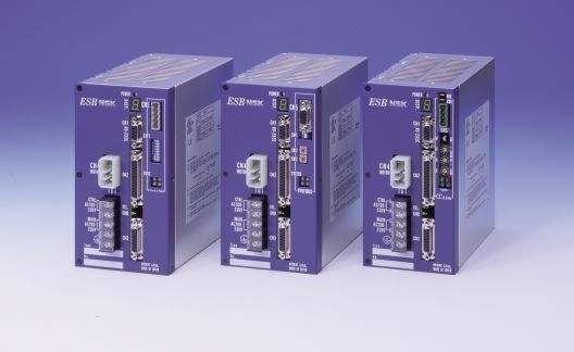
1. System Configuration
1.1 System Configuration
✽
Handy Terminal • Sequencer
FHT11 • Pulse train controller
HANDY TERMINAL 24V DC Power source
1# 2$ 3 4 5% -+
✽
6& 7' 8( 9) 0? .-
A
G H
B C D E
I J K
F
L
ESB type Driver Unit
M N O P Q R
S T U V W X
Y Z ? /
SHIFT ESC CTRL BS SP ENT
POWER
DISP.
RS-232C communication CN1
RS-232C
Control power
CN4
MOTOR CN2
Control I/O signal
Main power TB1
CTRL L
AC100-
230V N
Single-phase 200—230V AC
MAIN
AC200-
230V
L
N
YSB Series Megatorque Motor ✽
CN3
Single-phase 100—120V AC Type
No. NSK Ltd.
MADE IN JAPAN
Cable set ✽
Resolver cable
Motor cable
✽ Provided by NSK.
1.2 Application
Features and Main Reason for Incorporation
Classification Application
High Accuracy High Speed High Rigidity Compactness Cleanliness Maintenance Free
CVD, Wafer washing, Ion implanting ✓ ✓ ✓ ✓
Semiconductor
manufacturing Wafer polishing, CMP etc ✓ ✓ ✓
equipment Semiconductor transportation/
✓ ✓ ✓ ✓
Inspection/Processing
LCD manufacturing LCD transportation/Inspection/ ✓ ✓ ✓ ✓ ✓
equipment Processing
Electric component assembly ✓ ✓ ✓ ✓ ✓
machines
Electronic component high speed
✓ ✓ ✓ ✓ ✓
assembly machines
Assembly machines
Automotive parts assembly machines ✓ ✓
Various assembly machines ✓ ✓ ✓ ✓
Machine tools Tool rest feeding and ATC magazines ✓ ✓ ✓
Machinery parts inspection ✓ ✓ ✓
Electric component inspection ✓ ✓ ✓
Inspection/Testing
apparatus Optical component inspection ✓ ✓ ✓
Liquid medicine inspection ✓ ✓ ✓
Various inspection/Testing apparatus ✓ ✓ ✓
Various assembly robots ✓ ✓ ✓ ✓ ✓
Robots Various transportation robots ✓ ✓ ✓
Inspection/Transportation robot in ✓ ✓ ✓ ✓ ✓
clean rooms
Transportation Various work transportation equipment ✓ ✓ ✓ ✓
5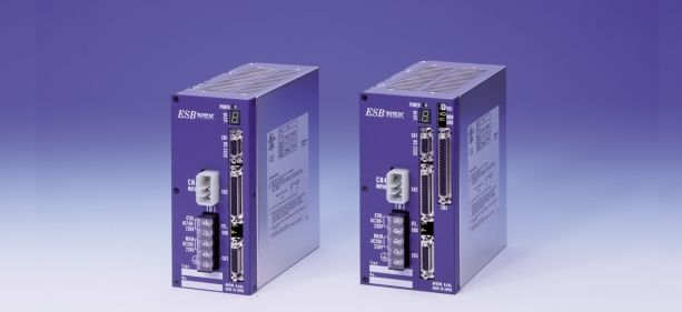
YSB Series Megatorque Motors

1.2.1 Examples of Application

                                                                 Megatorque Motor
                                                                 (Processing station)
                                         CD or DVD                                        Megatorque Motor
                          Robot arm                                                       (Loading/Unloading station)

                                       Processing
                                       equipment side
    Stocker
                                      Megatorque Motor

Transportation
equipment side                                                                             Megatorque Motor
                                                                                           (Assembly/Inspection station)

    Robot arm and stocker for                                                           Electrical component
    CD/DVD processing line                                                              processing line

     Driving mechanism of                                                               Processing line for
     ATC magazine                                                                       automotive parts

                                         Tools

                                                         Megatorque Motors

              Megatorque Motor

                                                                                                                           6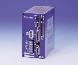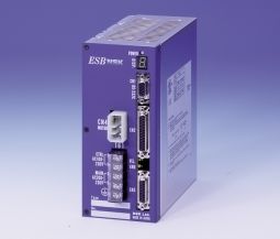
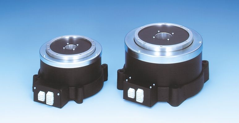
2. Megatorque Motors

                                     YSB 2020                                                                      YSB 3040

    2.1 Configuration of Motor Reference Number

     Example of Reference Number:                         M-YSB 2 020 K N 001
                                                                                                                                   Design serial number
                    YSB Series Megatorque Motor                                                                                            N: No brake
                    Motor size code                                                                              K: Standard (Incorprates absolute
                                                                                                                     position sensor.)
                    Maximum output torque (N•m)                                                                  J : Optional (Incorporates incremental
                                                                                                                     position sensor.)(2)

    2.2 Motor Specifications
                               Motor Reference Number
                                                                              M-YSB2020KN001                                          M-YSB3040KN001
        Functional Item (Unit)
        Maximum output torque                 (N•m)                                     20                                                      40

        Maximum current                       (A)                                        6                                                      6

        Maximum rotational speed (1)          (s-1)                                      3                                                      3

        Resolution of position sensor         (pulse/r)                              819 200                                                819 200

        Absolute positioning accuracy (sec)                                            150                                                     150

        Repeatability                         (sec)                                    ±1.6                                                   ±1.6

        Allowable axial load                  (N)                                     3 700                                                   4 500

        Allowable moment load                 (N•m)                                     60                                                      80

        Mass                                  (kg)                                      10                                                      16

                                                                Ambient temperature 0-40°C, Humidity: 20-80%, Use indoors, free from dust,
        Environmental conditions
                                                                condensation and corrosive gas. IP30 equivalent.(3)

    Notes:
    (1) Consult with NSK if the motor rotates in one direction continuously at a high speed exceeding 2 (s -1), or oscillates in very minute angle. Keep the flatness of
        motor mounting surface 0.02 mm or less, and mount the jigs so that its center gravity is not off the rotation axis of the motor. Othewise it will adversely affect
        on the life of the motor.
    (2) A motor equipped with an incremental position sensor is also available. Please consult with NSK.
    (3) IP30 is defined as below in a regulation of IEC 52. (International Electronics Commission)
        First digit following IP indicates the protection grade against the solids. The number 3 means the protection against penetration of a solid of 2.5 mm or larger
        into an enclosure. The second digit indicates a protection grade. The number 0 means there is no protection against water.

7
YSB Series Megatorque Motors
2.3 Dimensions of Standard Motor
YSB2020 equipped with absolute position sensor
2- φ 6H7 ( +0.012
0 )×7 Output rotor mounting holes 6-M5×0.8×7 2- φ 6H7 ( +0.012
0 )×5 Base mounting holes
(Chamfer C0.5) P.C.D.120 (60° equal pitch) 105+– 0.4 (Chamfer C0.5) 4-φ 7 drill-thru
✽(145) (6) ✽(42)
130+– 0.2 (1.5) 39
✽(3)
45°
✽ (R22)
✽ (R85)
15
.5°
0–
+0
22
.0
2
φ 130h8 –0.063
φ 110 +0.1
(φ 164.5)
0
130+– 0.2
0
✽(145)
( 30)
φ
12 0
+–0.0
2
Max.115
(126)
✽ (80) ✽ (46.5) 54
Connector: JST Corp.ELR-09V Connector: JST Corp.ELR-15V
Unit: mm
For the dimensions marked ✽, an extra 2–3 mm margin
is required for your workspace due to their variations.
YSB3040 equipped with absolute position sensor
Output rotor mounting holes 125+– 0.4
2- φ 6H7 ( +0.012
0 )×8 6-M6×1.0×8 (4) ✽(50) 2- φ 6H7 ( +0.012
0 )×5 Base mounting holes
(Chamfer C0.5) P.C.D.145 (60° equal pitch) (1) 44 (Chamfer C0.5) 4-φ 10 drill-thru
✽(180) ✽(38)
160+– 0.2 ✽(21)
90)
✽(3)
22.5°
✽(R
45°
✽(R105)
19
✽(R82.5)
0–
+0
.0
2
✽(R56)
✽(R40)
✽(R31)
φ 155h8 –0.063
φ 135 +0.1
(φ 206.5)
0
0
160+– 0.2
(180)
(φ 44)
145
+–0.0
67
2
Max.150
90
φ
✽(80) ✽ (52)
Connector: JST Corp.ELR-09V Connector: JST Corp.ELR-15V
Unit: mm
For the dimensions marked ✽, an extra 2–3 mm margin
is required for your workspace due to their variations.
8
3. ESB Type Driver Units

      ESB Model B3                                                                                                               ESB Model B5

    3.1 Configuration of Driver Unit Reference Number
              Example of
          Reference Number:                M-ESB YSB2020 A B 3 00                                                      Design serial number
                                                                                                                          00: Pulse train input (Photo coupler)
                                                                                                                          01: Pulse train input (Line receiver)
       ESB type Driver Unit
                                                                                                                Function
       Motor size code                                                                                            3: Standard (Max. 16 channels)
       Main power voltage A: 200–230V AC (single-phase)                                                           5: Increase program capacity (64 channels)
                          C: 100–110V AC (single-phase)                                                              Analog velocity command available
                                                                                                                  A: Device Net
       Specification of position sensor 2: Incorporates incremental position sensor                               B: PROFIBUS
                                        B: Incorporates absolute position sensor                                  C: CC-Link

    3.2 Driver Unit Specifications
    3.2.1 Standard Model (ESB Model B3)
    Position command                                Internal Program, Pulse Train Input, RS-232C Communication
                     Pulse train input              Maximum frequency: 819.2 Kpps
    Input signal
                     Control input                  Input pulse format: CW/CCW, Pulse and direction, or Quadrature        A/ B
                     Position feedback signal (1) Output format: Line driver (Only        Z can be switched to open collector)
    Output signal
                     Control output                 Driver Unit ready, In position, Brake control, Velocity threshold, Target proximity/In target area
                                                    Excess position error, Software thermal, CPU error, Position sensor error, Over current, Over heat,
    Alarms
                                                    Main AC line trouble, Control AC line under voltage

                                                    Analog velocity monitor, Alarm status, RS-232C communication monitor
    Monitoring function
                                                    (Parameters, program contents, position data, and alarm status)
    Communication                                   RS-232C serial communication, Baud rate: 9600 bps.
                                                    Automatic gain adjustment by RS-232C communication command (Automatic tuning)
    Others
                                                    Programmed acceleration profiling (2) (Modified sine, modified trapezoid, cycloid and arc patterns)
    Main power voltage                              200-230V AC, ±10%, Single-phase 50/60 Hz                 100-110V AC, ±10%, Single-phase 50/60 Hz
                                                    YSB2020: 1.0KVA                                          YSB2020: 0.7KVA
    Main power capacity
                                                    YSB3040: 1.2KVA                                          YSB3040: 0.9KVA
    Environmental condition                         Operating temperature: 0–40°C, Humidity: 20–90%, Use indoors. Free from dust, condensation, and corrosive gas.

    3.2.2 Optional Functions
    Increased program capacity                                      Internal program 64 channels
    Analog velocity command (Analog torque command)                 ±10V analog command
    Compatible to field bus (3)                                     CC-Link (4), PROFIBUS, DeviceNet (5)
    Notes:
    (1) Resolution of the position feedback signal is 51 200 (pulse/r).
    (2) Function of programmed cam profile acceleration is not available for the field bus specifications.
    (3) Detailed consultation with NSK is separately required for the field bus specifications.
    (4) CC-Link is the registered trademark of CC-Link Association.
    (5) DeviceNet is the registered trademark of Open DeviceNet Vendor Association Incorporated.

9
YSB Series Megatorque Motors
3.3 ESB Model B3 Driver Unit
Dimensions of Driver Unit
Standard model B3 (16 channels) 80
75
170 50
6
8.5
POWER
DISP.
CN1
RS-232C
CN4
180
215
MOTOR CN2
TB1
CTRL L
AC100- VEL
230V N GND
MAIN L
AC200-
230V N
CN3
Type
No. NSK Ltd.
MADE IN JAPAN
Unit: mm
3.3.1 Input/Output Signal Specifications of CN2 Connector
Input/Output Signal Code Pin No. Signal Name Function
CWP+ 8 CW pulse train (+) The motor rotates clockwise by the pulse train input.(1)
CWP– 21 CW pulse train (–) (This part can be a direction or a B signal.)
CCWP+ 7 CCW pulse train (+) The motor rotates counterclockwise by the pulse train input.(1)
CCWP– 20 CCW pulse train (–) (This part can be a pulse train or a A signal.)
EMST 12 Emergency stop Stops the motor and locks the servo.
SVON 25 Servo on This signal sets the motor servo on state.
PRG0 9 Internal program • channel selection 0 (2)
Imput signal
PRG1 22 Internal program • channel selection 1 (2) A combination of ON and OFF of these 0–3 signals
PRG2 10 Internal program • channel selection 2 selects a channel (0–15) to execute its internal program.
PRG3 23 Internal program • channel selection 3
After a start of Homing, an activation of this signal
HLS 11 Home position limit switch
completes the Homing.
RUN 24 Positioning start Start the internal program of selected channel.
DC24 13 External power supply External power supply for the input signals (DC24V, 0.2A or over)
CHA 6 Position feedback signal A Pulse signals indicate a rotational speed of the motor.
13 DC24
SVON
RUN
25
24
12 EMST CHB 5 Position feedback signal B Output format is line driver. (A jumper can switch Z
PRG3 23
11
10
HLS
PRG2 CHZ 17 Z/Digital position signal MSB signal only to the open collector format.)
PRG1 22
9 PRG0
CWP–
CCWP–
21
20
8 CWP+ ✽CHA 19 Position feedback signal ✽ A
7 CCWP+
∗CHA 19
6 CHA ✽CHB 18 Position feedback signal ✽ B Reversed output of position feedback signal
∗CHB 18
5 CHB
CHZ
SGND
17
16
4 ∗CHZ ✽CHZ 4 ✽ Z/Digital position signal MSB
3 BRK
DRDY+ 15
IPOS 14
2 DRDY– Output signal SGND 16 Signal ground Ground connection for position feedback signal.
1 COM
DRDY+ 15 Driver Unit ready (+) This signal notifies that the Driver Unit is ready for operation.
(This signal opens when the Driver Unit is not ready or an
DRDY– 2 Driver Unit ready (–) alarm is given.)
IPOS 14 Positioning completed This signal notifies a completion of positioning.
BRK 3 Brake control signal Output of brake signal (Normally closed) (3)
COM 1 Output signal, common Common for position complete and brake control signals
Notes:
(1) When looking at the motor from the rotor side. (3) These signals can be switched to the signals outlined below by
(2) These 2 signals can be switched to the following signals by the the setting of parameters.
setting of a parameter. SPD: Velocity output, NEAR: Target proximity/In target area,
OVER: Warning.
Input/Output Signal Code Pin No. Signal Name Function
JOG 9 Jog Starts jog.
Imput signal
DIR 22 Setting rotational direction This signal is to set the rotational direction of jog.
OTP 9 Overtravel limit switch (+) Overtravel input signal for clockwise rotation
Imput signal
OTM 22 Overtravel limit switch (–) Overtravel input signal for counterclockwise rotation
103.4 ESB Model B5 Driver Unit (Option)
Dimensions of Driver Unit
Model B5 (Increased in program capacity)
95
75
170 50
6
8.5
POWER VR1
MON.
DISP.
GND
CN1
RS-232C
CN4
180
215
MOTOR CN2
CN5
TB1
CTRL L
AC100- VEL
230V N GND
MAIN L
AC200-
230V N
CN3
Type
No. NSK Ltd.
MADE IN JAPAN
Unit: mm
3.4.1 Input/Output Signal Specifications of CN2 Connector
Input/Output Signal Code Pin No. Signal Name Function
CWP+ 8 CW pulse train (+) The motor rotates clockwise by the pulse train input.
CWP– 21 CW pulse train (–) (This part can be a direction or signal B.)
CCWP+ 7 CCW pulse train (+) The motor rotates counterclockwise by the pulse train input.
CCWP– 20 CCW pulse train (–) (This part can be a pulse train or a A signal by switching.)
EMST 12 Emergency stop Stops the motor and locks the servo.
SVON 25 Servo on This signal sets the motor servo on state.
Input signal HLS 11 Home position limit switch After Homing starts, this signal’s activation completes the Homing.
CLR 10 Clear input This signal clears alarm state and errors in the position error counter.
LVG 24 Lower gain Switches lowering gain function ON and OFF.
OTP 9 Overtravel limit (+) Overtravel limit input for clockwise rotation
OTM 22 Overtravel limit (–) Overtravel limit input for counterclockwise rotation
HOS 23 Start homing To be used for Homing
DC24 13 External power supply External power supply for the input signals (DC24V, 0.2A or over)
CHA 6 Position feedback signal A
Pulse signals indicate a rotational speed of the motor.
CHB 5 Position feedback signal B Output format is line driver.
(A jumper can switch Z signal only to the open collector format.)
CHZ 17 Z/Digital position signal MSB
✽CHA 19 Position feedback signal ✽ A
✽CHB 18 Position feedback signal ✽ B Reversed output of position feedback signal
✽CHZ 4 ✽ Z/Digital position signal MSB
Output signal
SGND 16 Signal ground Ground connection for position feedback signal
DRDY+ 15 Driver Unit ready (+) This signal notifies that the Driver Unit is ready for operation.
DRDY– 2 Driver Unit ready (–) (This signal opens when the Driver Unit is not ready or an alarm is given.)
IPOS 14 Positioning completed This signal notifies a completion of positioning.
BRK 3 Brake control signal Output signal of brake control (Normally closed)
COM 1 Output signal, common Common for position complete and brake control signals
11YSB Series Megatorque Motors
CN2 CN5
CN2 Pin out CN5 Pin out
19 DC24
— 37
18 STP
INH 36
17 RUN
13 DC24 — 35
SVON 25 16 PRG5
12 EMST — 34
LVG 24 15 PRG4
— 33
11 HLS 14 PRG3
HOS 23 — 32
10 CLR 13 PRG2
OTM 22 DIR 31
9 OTP 12 PRG1
CWP– 21 JOG 30
8 CWP+ 11 PRG0
CCWP– 20 — 29
7 CCWP+ —
∗CHA 19 — 28
10
6 CHA 9 —
∗CHB 18 NON+ 27
AIN+
5 CHB 8
CHZ 17 MON– 26
16
4 ∗CHZ — 25
7 AIN–
SGND
3 BRK 6 —
DRDY+ 15 — 24
2 DRDY– 5 —
IPOS 14 — 23
1 COM 4 NEARB
HCMP 22
3 NEARA
HOME 21
2 OVER
SPD 20
1 COM
3.4.2 Input/Output Signal Specifications of CN5 Connector
Input/Output Signal Code Pin No. Signal Name Function
DC24 19 External power supply Power supply for input signals (DC24V, 0.2A or over)
STP 18 Positioning stop Interrupts positioning
RUN 17 Positioning start Starts an internal program of selected channel.
PRG0 11 Internal program •Channel selection 0
PRG1 12 Internal program •Channel selection 1
PRG2 13 Internal program •Channel selection 2 A combination of ON and OFF of these 0–5
signals selects a channel (0–64) to execute its
PRG3 14 Internal program •Channel selection 3 internal program.
Input signal
PRG4 15 Internal program •Channel selection 4
PRG5 16 Internal program •Channel selection 5
JOG 30 Jog Starts jog.
DIR 31 Jog direction Sets direction of jog.
AIN+ 8 Analog command input Input port for velocity or torque analog command
AIN– 7 Ground of analog command input when specified
Prohibits accepting the pulse train input or
INH 36 External command prohibited
analog input command.
MON+ 27 Analog monitor output Analog output to monitor controlled status of the motor
MON– 26 Monitor output ground Ground for the monitor output
HCMP 22 Home position established This signal notifies that the home position is fixed.
HOME (2)
21 Homing completed/Tell home position Reports completion of homing or home position.
Output signal SPD 20 Velocity threshold Reports motor speed.
COM 1 Control output common Common for control output signal
OVER 2 Warning This output closes when a warning is given.
NEARA (1)
3 Target proximity/In target area A Reports the motor is approaching the target or the
NEARB (1)
4 Target proximity/In target area B motor is in the target area.
Notes:
(1) You may select “Target proximity” or “In target area” by setting a parameter.
(2) You may select “Homing completed” or “Tell home position” by setting a parameter.
123.5 Electrical Specifications of CN2 and CN5 Connectors
● General Inputs DC24V
3.3k
Input voltage 24V DC±10%
✽
680
Impedance 3.3kΩ
Input current 10 mA or less (per port)
Note: Driver Unit side
✽ Can be used as a minus common.
● Pulse Train Inputs 120
Input voltage 5V DC±10% Input H (+)
680
Impedance 240Ω
120
Input current 25 mA or less Input L (–)
Driver Unit side
● General Outputs
Output (+)
Maximum switching capacity 24V DC/50mA
Saturation voltage 2V or less
Output (–)
Driver Unit side
● Position Feedback Signals
CHA
• CHA, ✽CHA, CHB, ✽CHB, CHB
Line driver
Output format
• CHA, ✽CHA, CHB, ✽CHB, ∗CHA
∗CHB
Line driver or open collector SGND
Driver Unit side
Texas Instruments Inc.
Driver used
SN75ALS912
Texas Instruments Inc. CHZ
Recommendable
SN75ALS193 or AM26LS32
line receiver
equivalent
Maximum collector current 100 mA
∗CHZ
SGND Driver Unit side
Maximum collector voltage 24V DC At open collector format
Saturation voltage 1V or less
● Analog Command Inputs
20k
Maximum input voltage ±10V DC AIN+ –
Impedance 20kΩ
AIN– +
Maximum input current 0.5mA
Driver Unit side
10k
● Analog Monitor Outputs 1000p
Output format Operation amplifier output
–
Maximum output voltage ±10V±10% MON+
+
Saturation current 4 mA or less MON–
Driver Unit side
13YSB Series Megatorque Motors
3.6 Field Bus Specifications (Option)
Compatibility to the field bus contributes to the networking
user’s production equipment and cost reduction.
100 100 95
75 75 75
170 50 50 50
6 6 6
8.5
8.5
8.5
POWER POWER POWER MON.
CN5 GND
DISP.
DISP.
DISP.
CN5
1 2 3 4 5
CN1 CN1 CN1
CN5
RS-232C
RS-232C
RS-232C
SW1 SW1
ON
TERM.
SW4
1 2 3 4 5 6 7 8
2 3
SW2
4 5 6
SW1
0 1
STATION NO.
9
7 8
SW3 2 3
4 5 6
SW2
0 1
9
7 8
2 3
B.RATE
CN4 CN4 CN4
SW3
4 5 6
0 1
STATUS
STATUS
9
180
215
180
215
180
215
7 8
MOTOR CN2 MOTOR CN2 MOTOR CN2
DeviceNet PROFIBUS STATUS
TB1 TB1 TB1 CC-Link
CTRL L CTRL L CTRL L
AC100- VEL AC100- VEL AC100- VEL
230V N GND 230V N GND 230V N GND
MAIN L MAIN L MAIN L
AC200- AC200- AC200-
230V N 230V N 230V N
CN3 CN3 CN3
Type Type Type
No. No. No.
NSK Ltd. NSK Ltd. NSK Ltd.
MADE IN JAPAN MADE IN JAPAN MADE IN JAPAN
Unit: mm
143.6.1 Features of ESB Model BC Driver Unit (CC-Link)
● ESB Driver Unit of Megatorque Motor System provides the field bus (CC-Link)
compatibility.
● You can set station numbers and the baud rate with the switches provided on the
Driver Unit’s front panel.
● Monitoring communication status by LED and setting of the terminating resistor are
available.
● The ESB Driver Units are compatible with CC-Link Ver. 1.10.
3.6.2 CC-Link Specifications
CC-Link station specification Remote device station (Exclusive station: 1)
Positioning command Internal programmed operation via CC-Link or RS-232C communication
CN2 Emergency stop, Home position limit switch, Overtravel limit switch (CW, CCW)
Input signal Control input CC-Link
Emergency stop, Servo on, Internal program start, Homing start, Clear, Jog,
Jog direction, Internal program channel select, Velocity change
(CN5)
CN2 Driver Unit ready, Positioning completed, Brake control
Output signal Control output CC-Link Driver Unit ready, Positioning completed, Brake control, Home position
established, Processing internal pulse, Warning, Target proximity/In target area
(CN5) output A and B, Selected channel number
Excess position error, Software thermal, CPU error, Position sensor error, Over
Alarms
current, Over heat, Main AC line trouble, Control AC line under voltage
Alarm status, Analog velocity monitor, Alarm status, RS-232C communication
Monitoring function
monitor (Parameters, program contents, position data, and alarm status)
Serial RS-232C communication: Baud rate 9600 bps
CC-Link communication: Baud rate: 156k/625k/2.5M/5M/10Mbps
Communication
Station number: 1–64
Terminating resistor: None/110Ω/130Ω
15YSB Series Megatorque Motors
3.6.3 CC-Link System Configuration
Note book personal computer
Handy Terminal FHT11
Sequencer
Driver Unit
Master side
RS-232C
CC-Link
To other devices
Main Power connected to CC-Link Megatorque Motor
Inputs of external
Single-phase 200–230V AC sensors
or
Single-phase 100–120V AC
Cable Set
3.6.4 CC-Link Interface
CC-Link connector
DA : Data A
1. DA
CC-Link
CN5 2. DB
DB : Data B
CN5
3. DG DG : Data ground
4. SLD
SLD : Shield
SW4
Upper: Terminating resistor 110Ω
SW1 SW4 Setting terminating resistor Middle: No terminating resistor
SW2 Bottom: Terminating resistor 130Ω
Station number = (SW2 × 10) + (SW3)
SW3 SW1
Setting station number ✽ Never set the numbers of 0 and 55
LED SW2 or over for station numbers
0: 156Kbps
1: 625Kbps
2: 2.5Mbps
SW3 Baud rate
3: 5Mbps
4: 10Mbps
5–9: Never set
RUN ERR
LED Data status indicator RD SD
163.7 Wiring Example
ESB Model B3 Driver Unit
Thermal sensor
CTRL CN4 MOTOR
Single-phase 200–230V AC L • Circuit breaker
or • Magnetic switch TB1 Megatorque Motor
Single-phase 100–120V AC N MAIN
• Noise filter etc.
CN3 SENSOR
Master controller
13 DC24
Handy Terminal FHT11
24V DC
Servo on 25 SVON
Emergency stop 12 EMST
Internal program •Channel selection 3 23 PRG3 CN1 RS-232C
Home position limit 11 HLS
Internal program •Channel selection 0 9 PRG0 Master controller
Internal program •Channel selection 1 22 PRG1 CN2
Positioning start 24 RUN
Driver Unit ready
Internal program •Channel selection 2 10 PRG2 DRDY+ 15
8 CWP+ DRDY– 2 24V DC
5V DC
Pulse train (CW) 21 CWP– CN2 BRK 3 Brake control
7 CCWP+ IPOS 14 Positioning
completed
Pulse train (CCW) 20 CCWP– COM 1
ESB Model B5 Driver Unit
Thermal sensor
CTRL CN4 MOTOR
Single-phase 200–230V AC L • Circuit breaker
or • Magnetic switch TB1 Megatorque Motor
Single-phase 100–120V AC N MAIN
• Noise filter etc.
CN3 SENSOR
Master controller
13 DC24
24V DC
Servo on 25 SVON
Handy Terminal FHT11
Emergency stop 12 EMST
Homing start 23 HOS
Home position limit 11 HLS CN1 RS-232C
Overtravel limit (+) 9 OTP
Overtravel limit (–) 22 OTM CN2
Lower gain 24 LVG
Clear 10 CLR
8 CWP+
5V DC
Pulse train (CW) 21 CWP–
7 CCWP+
Pulse train (CCW) 20 CCWP–
19 DC24
24V DC
Positioning start 17 RUN
Internal program •Channel selection 5 16 PRG5
Internal program •Channel selection 4 15 PRG4 Master controller
Internal program •Channel selection 3 14 PRG3
Internal program •Channel selection 2 13 PRG2
Driver Unit ready
Internal program •Channel selection 1 12 PRG1 DRDY+ 15
CN5
Internal program •Channel selection 0 11 PRG0 DRDY– 2 24V DC
Jog 30 JOG CN2 BRK 3 Brake control
Jog direction 31 DIR IPOS 14 Positioning
Analog command completed
8 AIN+ COM 1
7 AIN– Homing
completed/
+ 27 MON+ HOME 21 Tell home
Analog monitor CN5 position
– 26 MON– COM 1
174. Cable Set YSB Series Megatorque Motors
Gray cable: For fixed use.
Black cable: Flexible type for moving use.
4.1 Configuration of Reference Number
Example of reference number: M-C 004 SB 03 Design serial number
01: Incremental positioning sensor (For fixed use)
03: Absolute positioning sensor (For fixed use)
11: Incremental positioning sensor (Flexible type)
Cable set 13: Absolute positioning sensor (Flexible type)
Cable length (m) SB: ESB Driver Unit
4.2 Dimensions of Cable Set
For Motor with absolute position sensor (M-C ✽ ✽ ✽ SB03)
Connector (JAT) Connector shell (JAE) Connector (JAE)
ELP-06V DA-C15-J10-F2 45.7 DAU-15pf - FO
Resolver cable
40.5
DA-C15-J10
JAE
For fixed use
(φ 12)
Flexible type
(φ 11)
For fixed use
Connector (JST)
Flexible type
ELP-15V 15
(φ 11)
(φ 13)
Motor cable
25
S1
S2
Connector (AMP)
24.6 172495-1 24 Thermal sensor terminal
(For protective circuit
L (100) against heat-up motor)
• Cables of design serial number 01 and 03 are for fixed use only. (Cannot be connected to moving part.)
• Minimum bending radius of the motor cable shall be 135 mm, and 110 mm for the resolver cable.
185. Handy Terminal
Handy Terminal FHT11 is an easy-to-handle RS-232C
communication terminal for inputting parameters and
programs to the ESB driver unit. You need just
connect it to the CN1 connector of the driver unit.
• LCD screen: 20 letters × 4 lines
• No external power source required.
• Cable length: 3m
5.1 Configuration of Reference
Number
Example of
reference number: M-FHT 11
Handy Terminal Serial number
6. Characteristics/Accuracy
6.1 Speed/Output Torque
3.0
YSB2020–100V
YSB3040–100V
2.5
YSB2020–200V
YSB3040–200V
Rotational speed, rps
2.0
1.5
1.0
0.5
0
0 10 20 30 40 50
Output torque, N•m
6.2 Runout (Unit: mm)
Output rotor
1 Rotor axial runout
Item Specification 2 Rotor radial runout
(1) Rotor axial runout 0.050 or less
(2) Rotor radial runout 0.050 or less
197. Selection YSB Series Megatorque Motors
It is essential to study the allowable load and output torque that requires positioning the motor at a desired time.
Refer to the motor specifications for the allowable axial and moment loads. Use the following formulas to obtain
an actual load to the motor.
7.1 Estimation of Actual Load
F
L
F
L
F
A
(1) When F is an external force: (2) When F is an external force: (3) When F is an external force:
● Axial load: Fa = F + total weight of ● Axial load: Fa = F + total weight of ● Axial load: Fa = total weight of
jigs/works jigs/works jigs/works
● Moment load: M = 0 ● Moment load: M = F × L ● Moment Load: M = F × (L+A)
Motor Reference Number YSB 2020 YSB 3040
A dimension (mm) 61.5 72.5
7.2 How to Use Charts for Minimum Positioning Time
Following the check of allowable loads, study the minimum time required to position the motor.
The charts provided below are for checking the minimum positioning time of the YSB Megatorque Motors. Refer to the charts
in the following cases.
● The user wishes to know which motor size should be selected for positioning within a required time, when the
indexing angle and the load inertia are predetermined.
● The user wishes to know the required time for positioning, when an indexing angle, the load inertia and the motor
size are predetermined.
These charts can be used only when the following conditions are satisfied;
1) The load is directly coupled to the rotor, neither using a mechanical speed reducer such as belt or gears nor coupling, and
is sufficiently rigid (natural frequency is 50Hz or over.)
2) No load torque is applied on a motor.
In addition, further examination is recommended when a motor is to be used in any of the following conditions.
1) Load inertia exceeds the allowable value so that it may not appear on the charts: Even in this case, driving a motor is not
always impossible, but may take a longer time than the theoretical value because considerable limitations will be placed on
the acceleration and the rotational speed.
2) When there is no chart applicable to the indexing angle: Separate calculation shall be made. However, the minimum time for
positioning cannot be obtained when the indexing angle is too small.
3) The settling time of 0.2 seconds is added initially. You may change the settling time to be shorter if you can relax the
repeatability.
Example: Motor: YSB3040 (100–110V AC) Moment of inertia: 1.25 kg• m2 (GD2: 5 kgf• m2) Index angle: 30˚
Following the arrows on the chart below right, the minimum positioning time is 0.5 seconds.
(Power voltage 100V AC Power voltage: 200V AC )
YSB 2020 YSB 3040
Index angle Index angle
1.5 2.0
180
180
1.5
Positioning time, s
Positioning time, s
1.0 90 90
45
1.0 45
30
30
0.5 15
15
0.5
0 0
0 0.5 1 5 0.1 0.5 1 5 10 20
Inertia GD 2, kgf •m2 Inertia GD 2, kgf•m2
0.05 0.1 0.5 1 0.05 0.1 0.5 1 5
2 2
Moment of inertia, kg •m Moment of inertia, kg•m
208. Combination
8.1 Motors Equipped With Absolute Position Sensor
Motor Reference Number Driver Unit Reference Number Power Voltage Main Specifications
M-ESB-YSB2020AB300 (1) 200-230V AC
M-YSB2020KN001 Internal program 16 channels (Acceleration profiling
M-ESB-YSB2020CB300 100-110V AC
pattern can be set to each channel)
M-ESB-YSB3040AB300 200-230V AC
Pulse train input (Photo coupler)
M-YSB3040KN001
M-ESB-YSB3040CB300 100-110V AC
M-ESB-YSB2020AB500 200-230V AC
Internal program 64 channels (Acceleration profiling
M-YSB2020KN001
M-ESB-YSB2020CB500 100-110V AC pattern can be only set to 32 channels)
M-ESB-YSB3040AB500 200-230V AC Analog velocity command
M-YSB3040KN001 Pulse train input (Photo coupler)
M-ESB-YSB3040CB500 100-110V AC
M-ESB-YSB2020ABA00 200-230V AC
M-YSB2020KN001
M-ESB-YSB2020CBA00 100-110V AC DeviceNet compatible
M-ESB-YSB3040ABA00 200-230V AC Internal program 64 channels
M-YSB3040KN001
M-ESB-YSB3040CBA00 100-110V AC
M-ESB-YSB2020ABB00 200-230V AC
M-YSB2020KN001
M-ESB-YSB2020CBB00 100-110V AC PROFIBUS compatible
M-ESB-YSB3040ABB00 200-230V AC Internal program 64 channels
M-YSB3040KN001
M-ESB-YSB3040CBB00 100-110V AC
M-ESB-YSB2020ABC00 200-230V AC
M-YSB2020KN001
M-ESB-YSB2020CBC00 100-110V AC CC-Link compatible
M-ESB-YSB3040ABC00 200-230V AC Internal program 64 channels
M-YSB3040KN001
M-ESB-YSB3040CBC00 100-110V AC
Standard cable (Hard type for fixed use) Optional Type (Flexible type for moving use)
Cable Set Reference Number Cable Length Cable Set Reference Number Cable Length
M-C002SB03 2m M-C002SB13 2m
M-C004SB03 4m M-C004SB13 4m
M-C008SB03 8m M-C008SB13 8m
M-C015SB03 15m M-C015SB13 15m
M-C030SB03 30m M-C030SB13 30m
Notes:
(1) For pulse train (line receiver format) position command, the last 2 digits of the driver unit reference number
change to 01 from 00.
Example: Internal program 16 channels (16 acceleration profiling patterns), pulse train (line receiver format)
M-ESB-YSB2020AB301
(2) The driver unit compatible to field bass dose not provide the pulse train input function. Therefore the last digits of
its reference number are 00 only.
219. International Safety Regulations
9.1 CE Marking
● Low Voltage Directive
NSK has worked with an EU Notified Body and an EU
Competent Body to ensure that the YSB Series
Megatorque Motor Systems conform to the pertinent
regulations of the EC Low Voltage Directive, thus any
system of the users, into which the Megatorque Motor
is incorporated as a “component,” can easily conform
to the EC Directives.
● Electromagnetic Compatibility Directive
We set conditions on the installation distance and
wirings between a YSB Motor and an ESB Driver Unit
and checked them for compliance with the pertinent
regulations of the MC Directive. Naturally, the way to
incorporate a YSB Motor and an ESB Driver Unit into
your system may differ from our checking conditions,
the users therefore require a final inspection of their
systems, which incorporates a Megatorque Motor
System, for conformity to EMC Directive (radiated
noise and conducted noise).
9.2 Underwriters’ Laboratory (UL)
● Motor
Conforms to UL1004 regulation
(File number: E216970)
● Driver Unit
Conforms to UL508C regulation
(File number: E216221)
● Cable Set
We use the material conforming to the UL regulations.
If you require more detailed information such as installing
conditions, please contact your local NSK
representative.
22You can also read