OPERATION MANUAL Flexeserve Zone
←
→
Page content transcription
If your browser does not render page correctly, please read the page content below
OPERATION MANUAL

                                    Flexeserve Zone®
FXZNA10N2S51 │ FXZNA10S3C51 │ FXZNA10S3C53 │ FXZNA10S3S53 │ FXZNA10S4C51 │ FXZNA10S4C53 │ FXZNA10S4S51
FXZNA10S4S53 │ FXZNA10S5C51 │ FXZNA10S5S51 │ FXZNA40N2S51│ FXZNA40S3C51 │ FXZNA40S3S51 │ FXZNA40S4C51
FXZNA40S4C53 │ FXZNA40S4S51 │ FXZNA60N2S51 │ FXZNA60S3C51 │ FXZNA60S3S51 │ FXZNA60S4C51 │ FXZNA60S4S51
                              FXZNA60S5C51 │ FXZNA60S5C53 │ FXZNA60S5S51

                          Customer Support [t] +44 (0)1455 638300
                                           (V13 January 2019)

IBS 40002210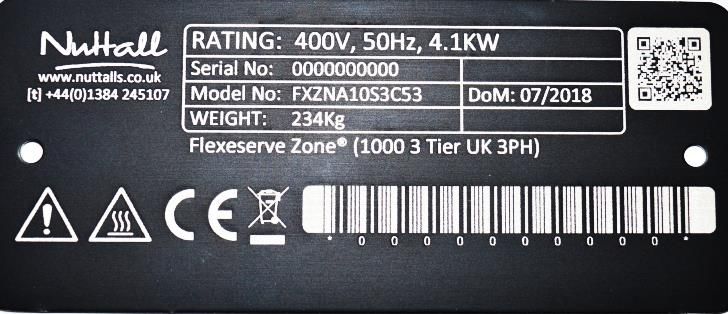
OPERATION MANUAL

Contents

Introduction                                          3

Safety Symbols                                        4

Safety Instructions                                   5

Specifications                                        6

Installation                                         10

Positioning                                          11

Moving                                               11

Electrical Connection                                12

Equipment Configuration                              13

Power On/Off                                         14

Switching On                                         15

Switching Off                                        17

Operation                                            18

Display and Merchandising                            19

Product Probing                                      19

Daily Cleaning                                       20

Troubleshooting                                      21

Spare Parts and Service                              22

Disposal of this Equipment                           22

Contact Us                                           23

IBS 40002210                 Page | 2   V13 (January 2019)

OPERATION MANUAL

Introduction
This manual has been developed as a guide to assist with the continued safe operation of the equipment.

The document covers many aspects of use and maintenance; the relevant level of training and competence
is required from the operators working with the equipment.

This information provided is for guidance only. The Alan Nuttall Partnership Ltd cannot be held responsible
for any accidents or injuries caused by instructions being carried out incorrectly or by the way the
information is depicted. The guide must be read and understood before using the equipment.

This manual has been composed with the utmost care. However, as the result of a constant commitment to
development and improvement, it may be the case that your equipment deviates in detail from what is
described in this manual.

The following instructions are only intended as guidelines for the installation, operation and maintenance
of the equipment. Furthermore, The Alan Nuttall Partnership Ltd accept no liability whatsoever for loss or
injury caused by the failure to strictly adhere to the safety guidelines and instructions in this manual,
whether due to carelessness, lack of the relevant training, qualification or competence, and during
installation, operation, maintenance or repair of the equipment.

This manual should be retained for future use.

© The Alan Nuttall Partnership Ltd 2018
Do not copy without written permission from The Alan Nuttall Partnership Ltd. All contents of this document
remain the intellectual property of The Alan Nuttall Partnership Ltd.

IBS 40002210                                     Page | 3                                V13 (January 2019)

OPERATION MANUAL

Safety Symbols
The symbols defined below, which are relied upon for safety, are used on the Flexeserve Zone® and/or
throughout this document.

                      WARNING/CAUTION
                      An appropriate safety instruction should be followed or caution to a potential
                      hazard exists.

                      DANGEROUS VOLTAGE
                      To indicate hazards arising from dangerous voltages.

                      HEAVY
                      This product is heavy and reference should be made to the safety instructions for
                      provisions of lifting and moving.

                      HOT SURFACE
                      To indicate that the marked item can be hot and should not be touched without
                      taking care.

                      INFORMATION
                      Information provided for trained and skilled operators only.

                      MAINTENANCE
                      Must only be undertaken by fully trained, qualified and competent engineers.

                      PROTECTIVE EARTH (GROUND)
                      To identify any terminal that is intended for connection to an external conductor for
                      protection against electric shock in case of a fault, or the terminal of a protective
                      earth (ground) electrode.

                      WASTE OF ELECTRICAL AND ELECTRONIC EQUIPMENT
                      When the end user wishes to discard this product, it must be sent to separate
                      collection facilities for recovery and recycling.

IBS 40002210                                    Page | 4                                 V13 (January 2019)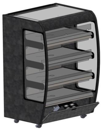
OPERATION MANUAL
Safety Instructions
This equipment may only be used by trained and skilled personnel. Any application that does not
conform to the specified use is considered hazardous.
The equipment must only be used for its intended purpose; any other application will be
considered improper. The equipment is designed to keep food warm that has been cooked, prior to
display. The equipment is not for cooking.
Heated areas of the Flexeserve Zone® exceed 70°C: only touch the components used to control the
equipment.
The equipment is not to be used for the storage or display of uncooked products. All foods must be
displayed in appropriate sealed containers/packaging.
Food products are to be pre-cooked and displayed in appropriate containers/packaging.
Do NOT place anything greater than 20 kg on to the display surface.
Do NOT cover or block exhaust vents.
Children should not be allowed to play with or near the equipment.
Before using the equipment:
- Inspect power cable for damage. If damaged, disconnect and isolate the Flexeserve Zone® unit;
- If the glass display shelf is cracked, isolate the Flexeserve Zone® unit and remove from service;
- Ensure that there are no foreign or combustible objects other than approved food packaging in
contact with the heated surfaces;
- Ensure that the display shelf is checked for signs of damage. If any damage is found, isolate the
electrical supply and report to The Alan Nuttall Partnership Ltd Customer Support Department.
Switch off the appliance:
- When not in use;
- Before carrying out any maintenance task, such as cleaning;
- Before moving the equipment.
To ensure that the equipment remains in optimum technical condition, maintenance work should be
carried out at least once a year by a recommended Nuttall Service Partner.
The end user is fully responsible for the fulfilment of locally applicable safety regulations and guidelines at
all times.
Any safety warnings and/or instructions attached to the equipment are part of the safety features. They
must not be covered or removed, and must be present and legible during the life of the product.
Immediately replace damaged or illegible pictograms, warnings and instructions.
IBS 40002210 Page | 5 V13 (January 2019)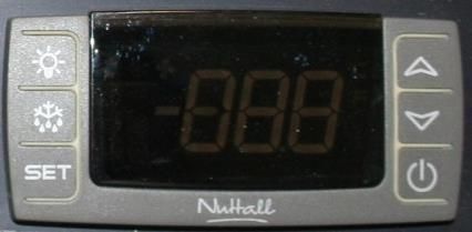
OPERATION MANUAL

Specifications
The Flexeserve Zone® range of products detailed within this manual are a series of hot-holding countertop
or floor standing units for the display of pre-cooked hot food products, in a container or closed packaging in
commercial outlets.

Each zone maintains the food products to a fixed temperature of between 65°C and 90°C by means of an air
circulation heater.

   NOTE: The Flexeserve Zone® will be factory set to maintain a minimum of 85°C air temperature.

The Flexeserve Zone® Countertop display units are provided with two zones (shelves).

The Flexeserve Zone® floor standing display units are provided with three to five zones (shelves). The
Flexeserve Zone® display units are supplied on castors, the front being lockable when in position.

The Flexeserve Zone® range is cord connected and supplied with an appropriate cord set, and for indoor
use only.

The ambient conditions required to operate the equipment are between 18°C to 40°C, with a maximum
relative humidity of 70%.

Overall Dimensions – 2 Tier Unit

                                                                                      A
                           B

                                                                    C

               Width (A)              Depth (B)               Height (C)             Weight

                356 mm                 660 mm                 884 mm                  72 kg

                556 mm                 660 mm                 884 mm                  88 kg

                975 mm                 660 mm                 884 mm                  106 kg

IBS 40002210                                       Page | 6                                   V13 (January 2019)
OPERATION MANUAL

Overall Dimensions – 3 Tier Unit

                        B                                        A

                                                      C

           End Panels       Width (A)   Depth (B)   Height (C)   Weight

               Curved                   830 mm                   132 kg
                            450 mm                  1520 mm
               Square                   855 mm                   136 kg

               Curved                   830 mm                   145 kg
                            556 mm                  1520 mm
               Square                   855 mm                   148 kg

               Curved                   830 mm                   234 kg
                            975 mm                  1520 mm
               Square                   855 mm                   237 kg

IBS 40002210                            Page | 7                     V13 (January 2019)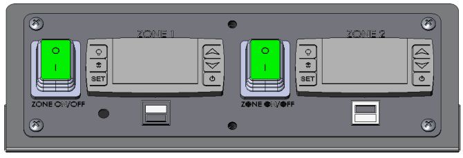
OPERATION MANUAL

Overall Dimensions – 4 Tier Unit

                            B                                        A

                                                         C

               End Panels       Width (A)   Depth (B)   Height (C)   Weight
                Curved                      865 mm                   156 kg
                                450 mm                  1865 mm
                Square                      855 mm                   159 kg

                Curved                      865 mm                   217 kg
                                556 mm                  1865 mm
                Square                      855 mm                   220 kg

                Curved                      865 mm                   320 kg
                                975 mm                  1865 mm
                Square                      855 mm                   323 kg

IBS 40002210                                Page | 8                     V13 (January 2019)
OPERATION MANUAL
Overall Dimensions – 5 Tier Unit
A B
C
End Panels Width (A) Depth (B) Height (C) Weight
Curved 556 mm 873 mm 1970 mm 220 kg
Square 556 mm 855 mm 1970 mm 223 kg
Curved 975 mm 873 mm 1970 mm 340 kg
Square 975 mm 855 mm 1970 mm 343 kg
IBS 40002210 Page | 9 V13 (January 2019)OPERATION MANUAL
Installation
WARNING
Installation of these units should be carried out by appropriately qualified and skilled
personnel. Failure to do so may invalidate the warranty.
The equipment will be delivered to site boxed on a pallet.
Remove all packaging materials from the unit and dispose of correctly, in accordance with local regulations.
Care must be taken when removing packaging so not to damage or scratch the painted, glass or stainless
steel surfaces.
Remove all temporary tape.
Prior to the first use, clean with a proprietary cleaning solution, following the manufacturers’ instructions.
Refer to the cleaning and maintenance section of this document. Ensure that excessive water is NOT used.
Do NOT use abrasive detergents.
If there are any signs of damage, contact The Alan Nuttall Partnership Ltd immediately. Failure to report
faults, defects or missing items upon delivery may incur charges. Deliveries must only be signed off if they
are in a satisfactory condition.
Ensure that safe manual handling practices are employed at all times. The unit should be lifted into position
using the correct lifting procedures, in line with local and regional safety policies.
The following considerations must be given to the site of installation:
Avoid placing sources of heat near the appliance.
Do NOT install the appliance near other equipment that generates high temperatures in order to
avoid damage.
The equipment should be sited so that it is not affected by draughts from doors or air conditioning
systems. Temperature fluctuations are likely to occur if the equipment is not sited appropriately.
This will have an adverse effect on product temperatures and may increase running costs.
Ensure that the floor supports the weight of the unit at full capacity.
Ensure that the unit is installed on a flat, even surface.
The supporting or surrounding surfaces for the appliance must be:
Non-combustible;
Level, flat and even;
Able to support the appliances weight at full load, without undergoing deformation or structural
failure;
Immovable.
IBS 40002210 Page | 10 V13 (January 2019)OPERATION MANUAL
Positioning
WARNING
Installation of these units should be carried out by appropriately qualified and skilled
personnel. Failure to do so may result in unsafe operation or personal injury.
WARNING
Adequate provision should be made for lifting and positioning the unit to avoid risk of
damage or injury. Sufficient personnel should be available to handle each unit without
contravening company or site health and safety policies.
It is recommended that a minimum of two persons are required for placing the equipment into position.
The equipment must be kept in the vertical orientation at all times.
Once the unit is placed in the desired location, it should be prevented from being moved.
The Flexeserve Zone® floor standing units (3, 4 and 5 tier units) have castor brakes fitted that should be
applied. The castor brakes are located to the front elevation of the unit, as shown in the illustration below.
Front counter elevation
showing front brake castors
Moving
Before moving the unit, isolate and disconnect the power cord from the wall socket. Stow the electrical
power cord so that it does not become damaged during repositioning.
The units are not suited to pass over ledges or obstacles. Make sure that the wheels can move freely and
never come into contact with the power cord (see figure below).
Plug Wall socket
IBS 40002210 Page | 11 V13 (January 2019)OPERATION MANUAL
Electrical Connection
WARNING
Connection must only be carried out by suitably trained, qualified and skilled
engineers, in accordance with all regional and local electrical codes.
The appliances are electrically rated for a 230 V or 400 V, 50 Hz electrical supply.
The equipment is designed to be installed as a cord connected device, 13 A single phase, 16 A single phase,
16 A 3 phase and 32 A single phase supplies for the applicable unit. A 13 A plug top, 16 A single phase
commando, 16 A 3 phase commando, or a 32 A single phase commando cord set will be fitted to the
corresponding unit.
The equipment must be connected to a branch circuit protected grounded supply.
Each unit must have its own dedicated power supply.
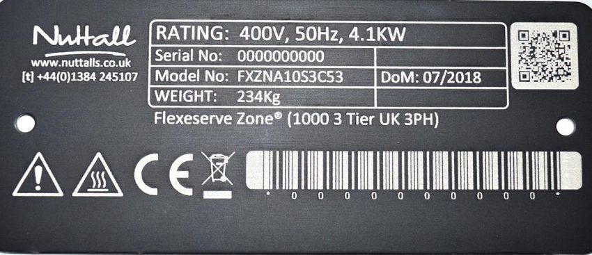
Note: For electrical ratings of the unit, refer to the electrical rating plate located on the side of the
control panel. An example is shown below.
It is highly recommended to provide the equipment with an accessible means of isolation external to the
equipment, i.e. a wall isolator switch.
Electrical Ratings
Total Power
Model Width Countertop 3 Tier Unit 4 Tier Unit 5 Tier Unit
400 mm 1300 W 2100 W 2700 W N/A
600 mm 1300 W 2100 W 2700 W 3400 W
1000 mm 2700 W 4100 W 5500 W 6900 W
WARNING
For all types of installation, ensure that the mains lead is in a safe position. Under no
circumstances should any electrical cables or power points be installed directly in contact
with any part of the unit or pose a risk to safety.
If the mains power lead becomes damaged, isolate the equipment and remove from
service immediately until a replacement is fitted.
IBS 40002210 Page | 12 V13 (January 2019)OPERATION MANUAL
Equipment Configuration
CAUTION
Each zone/shelf must have the polycarbonate risers fitted to ensure safe and correct
operation.
CAUTION
The unit will not operate correctly without the front risers in the correct position.
Slide signage into the ticket edges. Close the valance panel when not in use.
Riser
Double-glazed end panel
Shelf
Ticket strip
Mains lead
Electrical box
Castor brake
IBS 40002210 Page | 13 V13 (January 2019)OPERATION MANUAL
Power On/Off
Each zone is supplied with an isolator or power switch to turn the display cabinet on or off, which is located
within the front valance of the display unit.
Set the switch/isolator to ‘I’ to apply power to the equipment and set to ‘O’ to power off.
2 Tier Units Example:
400 and 600 mm, 3, 4 and 5 Tier Units Example:
Mains isolator switch
1000 mm, 3, 4 and 5 Tier Units Example:
Mains isolator switch
WARNING
In an emergency, switch off the appliance and isolate fully from the mains supply. Ensure
that you take time to familiarise yourself with this location.
IBS 40002210 Page | 14 V13 (January 2019)OPERATION MANUAL
Switching On
Hot Individual Zones/Tiers
WARNING
In an emergency, switch off the appliance and isolate fully from the mains supply.
Ensure that you take time to familiarise yourself with this location.
CAUTION
The surface of the hot zones will become hot, reaching temperatures above 70°C.
Each of the model variants are supplied with one set of controls for each hot zone. The controls are located
behind the valance panel at the base of the equipment.
Ensure that the equipment is empty and clean, prior to switch on. Check the equipment is connected to a
power socket.
Before switching on the equipment, it is the operator’s responsibility to visually inspect the equipment to
ensure that there is no damage that may compromise safety.
Zone power switch
Zone indicator
I: On position
O: Off position
Programmer display
Switch on the zone power switch and the display will illuminate. The display will show the ambient
temperature. The equipment will begin to heat and reach the established temperature set-point
automatically, generally 85°C.
Where multiple hot zones are required, select and set the appropriate zone power switches to ‘on’
separately.
The hot zones should be left empty without interference and may take up to 60 minutes to reach operating
temperature. No products should enter the display area until it has reached the correct operating
temperature.
WARNING
Do NOT place unpacked food products directly on to the hot shelves.
IBS 40002210 Page | 15 V13 (January 2019)OPERATION MANUAL
Ambient Individual Zones/Tiers
WARNING
In an emergency, switch off the appliance and isolate fully from the mains supply.
Ensure that you take time to familiarise yourself with this location.
CAUTION
When switching from hot mode to ambient mode, the surface of the zones will remain
hot for a period of time. Ensure that the unit has sufficiently cooled before placing
ambient products into the zone.
Zone power switch
I: On position Heating
O: Off position enable/disable
button
Programmer display
Switch on the zone power switch and the display will illuminate. The display will show the ambient
temperature.
To select the ambient mode:
Press the heating enable/disable button and the display will read ‘OFF’. Visually, you will see that the fan
has stopped rotating and there is no air circulating around the zone. The zone is now in ambient mode.
Where multiple ambient zones are required, select and set the appropriate heating enable/disable button
to ‘on’ separately.
No products should enter the display area until the zone has cooled adequately to the required ambient
temperature.
To reactivate the heating mode:
Press the heating enable/disable button and the display will read the current operating temperature.
Visually, you will see that the fan has started rotating and air is now circulating around the zone. The zone
is now in heating mode.
IBS 40002210 Page | 16 V13 (January 2019)OPERATION MANUAL
Switching Off
Individual Zones/Tiers
CAUTION
When switched off or disconnected from the power source, the surface of the hot zones
may still be hot, and may take up to two hours to cool down.
WARNING
Cleaning and maintenance should only be carried out when sufficiently cooled and with
the mains supply isolated.
To switch off the respective zone, set the zone power switch to ‘O’ (central) position.
Zone power switch
O: Off position Zone indicator
Programmer display
When the zone is turned off, the temperature display and power switch will go blank, and the zone will be
switched off.
To isolate, fully disconnect the incoming mains supply by the equipment power switch/isolator, or by
disconnecting the power cord from the supply.
IBS 40002210 Page | 17 V13 (January 2019)OPERATION MANUAL
Operation
WARNING
Only if the operator has been trained and is skilled in the operation of the equipment
covered in this guide should this information be followed.
Do NOT attempt to cook products in the Flexeserve Zone® shelves.
Do NOT place cooking vessels into the Flexeserve Zone®.
Do NOT place anything greater than 20 kg onto the display surfaces.
The equipment will only hot-hold products that have initially been cooked, prior to display. Ensure that
food is transferred to the display area immediately after cooking in appropriate display containers or
packaging.
Ensure that temperatures of the displayed products are checked and recorded on a regular basis, in
accordance with local procedures.
The temperature of each zone is displayed by the appropriate zone controller and is for indication only. Do
NOT use this as a reference; regular probing of the product temperatures is to be performed.
The minimum and maximum set-point values have been pre-set in the factory to prevent the equipment
holding temperatures from being adjusted beyond legal and safety limits. These can only be adjusted by a
Nuttall appointed engineer.
To view the temperature of the unit, press the ‘SET’ button for half a second. To change the temperature,
press and hold the ‘SET’ button and, at the same time, press the arrow buttons to increase (▲) or decrease
(▼) the temperature. After the temperature has been set, the display will revert back to the operating
temperature, which will rise or fall as it reaches the set temperature.
The Alan Nuttall Partnership Ltd complies with health regulations, and are tested and certified to NSF
standards. You must operate the equipment properly using only calibrated thermometers to ensure
produce is thoroughly cooked to safety standards.
IBS 40002210 Page | 18 V13 (January 2019)OPERATION MANUAL
Display and Merchandising
Different products require varying display times. These must be considered to ensure the best quality and
temperature for consumption is achieved. The Alan Nuttall Partnership Ltd does not accept responsibility
for variances or loss of quality that may occur due to product differences.
All items placed in the unit should be in the correct packaging/containers, in line with in-store procedures
and best practice.
To ensure good heat conduction into the product, only place a single layer of products on the display area.
Remove products in damaged packaging from the equipment and clean as soon as possible.
Product Probing
INFORMATION
Legal requirements dictate all products displayed for an extended period within any
heated display area should be periodically probed throughout the day’s trading to ensure
the core temperature of the product is above the legal holding temperature of 63°C.
Refer to in-house operations manual for product probing instructions.
It is beneficial for the holding time to enter the product into the hot-hold unit as hot as possible for that
particular food product.
The equipment is not designed to increase product temperature; the products gradually fall in temperature
throughout the display period to ensure good product quality. It is critical that the entry core temperature
is as high as possible so that the maximum display time is achieved. The product will fall in temperature
during its display time regardless of the entry temperature; therefore a low entry temperature will reduce
display time.
At the end of recommended display times, any unsold products should be removed and disposed of, in
accordance with company and food safety standards.
The Alan Nuttall Partnership Ltd does not take responsibility for variances or loss of quality that may occur
due to product differences.
Checking of the Product Temperature
IBS 40002210 Page | 19 V13 (January 2019)OPERATION MANUAL
Daily Cleaning
CAUTION
Isolate the equipment fully before any cleaning is undertaken.
CAUTION
Ensure that the equipment has completely cooled before any cleaning is undertaken.
Only suitably trained personnel should carry out cleaning procedures.
Ensure that the power has been isolated.
Ensure that the zones are allowed to cool to room temperature. Clean the surface of the shelf with a damp
cloth soaked in mild, soapy water; never immerse the shelves in water.
Ensure that water is not allowed to pool or sit on the glass surface. Sanitise and dry, as required.
WARNING
If the surface glass is cracked or damaged, discontinue use.
Do NOT use excessive amounts of water.
Do NOT clean the equipment with high-pressure cleaners, jets of hot water or high-
pressure steam. All traces of food debris should be removed completely.
Do NOT use abrasive cleaning products as these could damage the finish of the
equipment. It is recommended that non-abrasive cleaning products are used. Do NOT
use glass cleaning products.
The risers and ticket edges can be removed and cleaned by lifting.
Risers and ticket edges
Glass merchandiser shelf
Once the front risers are removed, the glass merchandiser shelf, inner side wells, lamp diffuser glass and
external surfaces can be cleaned using mild, soapy water.
WARNING
Do NOT use abrasive detergents.
Ensure that all risers are refitted before use of the unit.
IBS 40002210 Page | 20 V13 (January 2019)OPERATION MANUAL
Troubleshooting
CAUTION
Never attempt to open electrical connection enclosures. Only approved, trained and
competent engineers should access the base of the unit and electrical areas.
WARNING
The information provided is for guidance only. The Alan Nuttall Partnership Ltd cannot be
held responsible for any accidents or injuries caused by instructions being carried out
incorrectly, or by the way the information is depicted.
Fault Cause Solution
It is beneficial for the holding time
Produce has been displayed in the to enter the product into the
equipment at a low temperature. holding unit as hot as possible for
that particular food product.
Relocate the equipment to a
Draughts from doorways and air more suitable location. If this is
Products are not maintaining conditioning units in the vicinity of not possible, raise the
temperature. the equipment can cause the temperature settings (call
temperature to drop. Customer Support, as an
Engineer is required to do this).
Increase the temperature using
Set temperature is too low.
the programmer.
Zone is not heating up. Call Customer Support.
Over-temperature thermostat has
Temperature display is blank. operated. Call Customer Support.
Programmer is faulty.
Check that the isolation switch is
No power.
switched on.
Zone fuse has tripped.
Unit is not operating. Over-temperature thermostat has Call Customer Support.
operated.
Mains circuit breaker of the store Check the mains distribution
has tripped. board in store.
Lights are not working. Light unit has failed. Call Customer Support.
This information is provided for guidance only and is not exhaustive. Always use best practice fault-finding
techniques to establish and eliminate faults.
Some faults must only be investigated by a trained and qualified Engineer. For assistance, contact Customer
Support on [t] +44 (0) 1455 638300.
IBS 40002210 Page | 21 V13 (January 2019)OPERATION MANUAL
Spare Parts and Service
For all spares and service requirements, please contact our Customer Support Helpline 24 hours a day, 7
days a week on [t] +44 (0) 1455 638300. During out of office hours, a technician will be available to provide
technical support.
Your product can be identified by the data plate located on the rear of the unit.
Electrical rating
Serial number
Model number
Model description
To help us process your service call efficiently, we will require the following information:
1. Model number;
2. Model description;
3. Serial number;
4. Site address;
5. Site telephone number;
6. Description of fault.
Disposal of this Equipment
WASTE OF ELECTRICAL AND ELECTRONIC EQUIPMENT
Penalties may be applicable for incorrect disposal of waste, in accordance with national
legislation.
This product should not be mixed with general household waste. For proper treatment, recovery and
recycling, please return this product to The Alan Nuttall Partnership Ltd or take this product to a designated
collection point where it will be accepted free of charge. Contact details can be found on the following
page.
Disposing of this product correctly will help save valuable resources and prevent any potential negative
effects on human health and the environment, which could otherwise arise from inappropriate waste
handling.
IBS 40002210 Page | 22 V13 (January 2019)OPERATION MANUAL
Contact Us
At The Alan Nuttall Partnership Ltd, we strive to make constant improvements. Feedback regarding any
concerns relating to this equipment is always welcome.
Customer Support [t] +44 (0) 1455 638300
Enquiries [t] +44 (0) 1455 638300
Customer Support [e] customer.support@nuttalls.co.uk
Enquiries [e] info@flexeserv.com
Customer Support The Alan Nuttall Partnership Ltd - Orchard House, Dodwells Road,
Hinckley, Leicestershire, United Kingdom LE10 3BZ
Enquiries The Alan Nuttall Partnership Ltd - Orchard House, Dodwells Road,
Hinckley, Leicestershire, United Kingdom LE10 3BZ
Website [w] www.flexeserve.com
IBS 40002210 Page | 23 V13 (January 2019)You can also read