Design of Counter Beam Tunnel Lights for CIE 88 : 2004 Regulation in Threshold Zone
←
→
Page content transcription
If your browser does not render page correctly, please read the page content below
Hindawi
International Journal of Optics
Volume 2020, Article ID 6145638, 9 pages
https://doi.org/10.1155/2020/6145638

Research Article
Design of Counter Beam Tunnel Lights for CIE 88 : 2004
Regulation in Threshold Zone

 Ming-Jui Chen,1 Hien-Thanh Le ,1,2 Lanh-Thanh Le ,1,2 Wei-Hsiung Tseng,3
 Wei-Yang Lee,1 Si-Yuan Chen,1 Sheng-Yen Chen,1 Hsing-Yuan Liao,1 Yung-Cheng Li,4
 and Hsiao-Yi Lee 1,5
 1
 Department of Electrical Engineering, National Kaohsiung University of Science and Technology, Kaohsiung 80778, Taiwan
 2
 Department of Technology, Dong Nai Technology University, Bien Hoa 830000, Dong Nai, Vietnam
 3
 Department of Aviation & Communication Electronics, Air Force Institute of Technology, Kaohsiung City 820, Taiwan
 4
 Department of Materials Science and Engineering, National Tsing Hua University, No. 101, Section 2, Kuang-Fu Road,
 Hsinchu 30013, Taiwan
 5
 Department of Graduate Institute of Clinical Medicine, Kaohsiung Medical University, Kaohsiung 807, Taiwan

 Correspondence should be addressed to Hsiao-Yi Lee; leehy@nkust.edu.tw

 Received 5 December 2019; Revised 27 February 2020; Accepted 3 March 2020; Published 30 March 2020

 Academic Editor: Sulaiman W. Harun

 Copyright © 2020 Ming-Jui Chen et al. This is an open access article distributed under the Creative Commons Attribution
 License, which permits unrestricted use, distribution, and reproduction in any medium, provided the original work is
 properly cited.
 To enhance driving safety, a counter beam light is proposed to meet CIE (International Commission on Illumination) speci-
 fications for tunnel lighting. The proposed new counter beam light (CBL) acts as a qualified counter beam light to help tunnel road
 lighting meet the CIE 88 : 2004 regulation standard in the threshold zone in both simulation and in practice. Through appropriate
 arrangements of the counter beam light and conventional fluorescent lights on the tunnel ceiling, we demonstrate that road tunnel
 lighting meeting CIE 88 : 2004 standards can be accomplished. Based on LiteStar four-dimensional simulation, the source file
 created through the measurement of the proposed CBL prototype achieved an average road surface brightness of 121 cd/m2, which
 is greater than the minimum regulation level of 105 cd/m2, a brightness uniformity of 0.88 (minimum regulation level of 0.4),
 longitudinal brightness uniformity of 0.98 (minimum regulation level of 0.6), a glare factor of 4.41% (maximum level of 15%), and
 a contrast revealing coefficient of 1.08, which is above the 0.6 minimum level in the threshold zone.

1. Introduction 100% for the first half of the threshold zone and reduces to
 40% by the end of the zone. The k factor is inversely pro-
The main objective of tunnel lighting is to allow traffic to portional to the contrast revealing coefficient qc, so if qc can
enter, pass through, and exit the enclosed section of the be elevated, the required Lth can be decreased, which can
tunnel safely [1–4]. These aims are achieved through the provide the necessary lighting conditions for the tunnel road
adequate illumination of the tunnel interior, which allows while decreasing the consumed electrical power and the
drivers to quickly adjust to the light and identify possible maintenance cost of lighting. However, since the new CIE
obstacles on the road in tunnels. The threshold zone is the 88 : 2004 regulation was published, updating tunnel lights to
first zone within the actual tunnel that extends for the same achieve a high contrast revealing coefficient is rarely per-
length as the stopping sight distance for the design [5–8]. formed, so few commercial tunnel lights are qualified as
When using the L20 method, the target luminance level Lth counter beam lights [12, 13, 7]. Many newly built tunnels,
(threshold zone luminance) for this zone is derived from the such as the Conway Eastbound tunnel on the A55 in the
portal luminance (L20) factored by the k value associated U.K., adopt symmetrical lights in threshold zone, guaran-
with the class of tunnel [9, 10, 11]. This level is maintained at teeing a qc of only more than 0.2 [14, 15, 16]. To decrease the
2 International Journal of Optics

Lth level and follow the CIE 88 : 2004 regulation and as where Ltr is the road surface luminance in the transition
counter beam lights can guarantee a qc higher than 0.6, they zone, Lth is the road surface luminance in the threshold zone,
are always considered for tunnel lighting. and t is the driving time in seconds. The necessary driving
 In this study, a freeform surfaced luminaire is proposed time in the transition zone ttr is then given by
to handle 400 W high-pressured sodium lamps to act as the − 0.714
 Lin
counterbeam lights for CIE 88 : 2004 tunnel road lighting. ttr � − 1.9 seconds. (2)
The efficiency and lifespan of white light emitting diodes Lth
(LEDs) have improved, but the golden light of high-pres-
 The threshold zone is the first inner region encountered
sured sodium lamps has the specific advantage of high fog
 when entering a tunnel and where the black-hole effect
permeability and low insect attraction, which increase driver
 critically dominates. Based on the CIE 88 : 2004 regulation,
safety in the threshold and exit zones, where the dangerous
 the threshold zone luminance is usually set to be higher than
black-hole effect or white hole effect need to be addressed. As
 Lth.:
a result, lights with high-pressured sodium lamps are still
commonly used in the entrances and exits of tunnels. The Lm
 Lth � , (3)
proposed counterbeam light was prototyped and its intensity 1/Cm ρ/π.qc − 1 − 1
distribution was measured using a goniophotometer to
obtain its far field data. By importing the data into tunnel where Lm � (τ ws × Latm + Lws + Lseq )/(τ ws × τ atm ), Cm is
lighting analysis software, we found that the counter beam the minimum required perceived contrast (–0.28), ρ is the
light combined with conventional fluorescent lights can reflectance factor of the target (0.2), τ ws is the windscreen
meet tunnel road lighting CIE 88 : 2004 regulations in the transmission factor (0.8), τ atm is the atmosphere trans-
threshold zone, yielding an average road surface luminance mission factor (1.0), Lseq = 5.1 × 10⁻⁴Σ Lije with Lije � (τ ws ×
Lav of 130 cd/m2, which is greater than the minimum reg- Lij ) + Lws is the equivalent veiling luminance, Lije is the
ulation level of 105 cd/m2, a luminance uniformity Uo of luminance of each section in front of the eye (cd/m2), Lij is
0.89 > 0.4 (minimum regulation level), a longitudinal lu- the average luminance of each section measured outside the
minance uniformity UL of 0.99 > 0.6 (minimum regulation car in front of the windscreen (cd/m2), Latm is the atmo-
level), a glare factor TI of 5.5% < 15% (maximum level), and a spheric veiling luminance (200 cd/m2, medium veiling level),
contrast display factor qc of 1.24 > 0.6 (minimum level) in Lws is the windscreen veiling luminance (100 cd/m2, medium
the threshold zone. veiling level), and qc is the contrast revealing coefficient
 (≥0.2 for symmetrical light systems or ≥0.6 for counterbeam
 light systems).
2. Principles Based on the Holladay–Stiles formula, the equivalent
 veiling luminance Lseq can be determined busing a graphical
The major difference between tunnel lighting and conven- method to identify Lth . The equivalent veiling luminance Lseq
tional road lighting is in the need for lighting by day is found from Lseq � 5.1 × 10⁻⁴Σ Lije with Lije � (τ ws ×
[17, 18, 19]. A driver needs to be able to see a certain distance Lij ) + Lws . The contrast revealing coefficient (qc � L/Ev) is the
ahead so that if an unexpected hazard appears, the driver can ratio between the luminance of the road surface and the
react and stop within that distance. When this distance vertical illuminance Ev at a specific location in the tunnel.
extends into a tunnel, the lighting level inside should be Cm is the minimum required perceived contrast, where 28%
sufficiently high to maintain visibility. If the lighting level is is recommended. This contrast is mostly negative (for any qc
not high, the driver will be unable to see into the tunnel, greater than 0.06 with a reflectance factor of the target equal
which is called the black-hole effect. During approach and to 0.2). To determine the threshold road luminance, the
entry into a tunnel, drivers’ eyes adapt to the darker sur- designer should start from the standardized figures for the
roundings. This adaptation is a continuous process, so the contrast revealing coefficient (either 0.2 for symmetrical
further into the tunnel the driver travels, providing the light systems or 0.6 for counterbeam light systems). To
tunnel is of sufficient length, the lighting level may be identify a more precise threshold luminance value, an it-
steadily reduced until it reaches a constant level in the tunnel erative process is necessary. After selecting an initial esti-
interior zone. On emerging from a tunnel into daylight, the mated figure for the average qc of the installation and
eye adapts far more quickly to the higher luminance level. calculating the correlated Lth, the real average qc of the
The lighting of a tunnel should be sufficient to prevent the installation may need to be calculated to verify initial as-
black-hole effect when a driver is unable to see into the sumptions. In general, the atmospheric transmissivity (τ atm )
tunnel. As such, tunnel road lighting must satisfy some for design purposes is assumed to be 1.0 and the trans-
stringent requirements, such as the CIE 88 : 2004 regulation. mission factor for the windscreen (τ ws ) is assumed to be 0.8.
 In order to avoid encountering the black-hole effect Disability glare reduces visibility and shall be minimized. If
when approaching the portal of a tunnel and to help drivers disability glare is controlled under tunnel lighting condi-
adapt to the lighting environment in a tunnel, there are five tions, then discomfort glare will also be controlled. Disability
lighting zones distributed throughout a tunnel such as access glare effects shall be quantified by means of threshold in-
zone, threshold zone, transition zone, interior zone, and exit crement (TI). Good uniformity of luminance must be
zone. The transition zone is given by provided on the road surface. The recommended minimum
 Ltr � Lth ×(1 · 9 + t)− 1,4 , (1) to the average value of the luminance on the road surface in
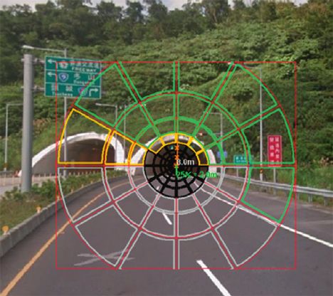
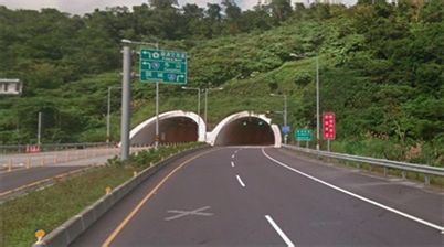
International Journal of Optics 3

clean conditions of the tunnel is 0.4. A longitudinal uni-
formity of 0.6 along the center of each lane is recommended
for the road. It is recommended that these values are in-
dependently reached on the length of the step. The values of
0.4 and 0.6 are those corresponding to the values for normal
road lighting provided in CIE 115-1995 [7, 13]. Figure 1: The entrance to the studied tunnel.
 Asymmetrical directional lighting, such as counterbeam
and probeam lighting, distributes patterns in only one di-
rection, either with or against traffic. Counterbeam lighting Lights to lights: 5.2m

directs the maximum optical intensity against traffic along
the driver’s line of vision, creating a high negative contrast.
By minimizing glare, drivers can clearly see the contours of
 Height of
the vehicle ahead. Probeam lighting directs the maximum Height of ceiling: 8.05 m
candlelight with the traffic away from the driver, providing lights: 4.9m
high object luminance and low road luminance, creating a
positive contrast. This system operates by minimizing lu-
minaire glare and increasing distance visibility.
 Sidewalk width: 1 m Road width: 4 m
3. Experimental Setup and Results Figure 2: The configuration of the trial tunnel geometry.
The tunnel for the study is located in the eastern part of
Taiwan, and its entrance is shown in Figure 1. The geometry
of the tunnel is shown in Figure 2, and its details are as with two T5 MASTER TL5 HE 35 W/840 SLV/20 fluores-
follows: motorway tunnel, 2 unidirectional bores; two traffic cence tubes with efficacy of 94 lumen/W were arranged
lanes, 3.75 m each; total width, 10 m; ceiling height, 8.05 m; regularly in the threshold zone. The layout of the lighting
and length of tunnel, >500 m. The tunnel orientation is south design is shown in Figure 6. The spacing of the lights was set
to north. to 1.6 m with one linear light followed by three counterbeam
 The amount of lighting required within a tunnel is de- lights in, and then repeating the same arrangement until the
pendent on the level of ambient lighting at which visual end of the zone. For the experiments, the design process of
adaptation for the driver is possible on the tunnel approach the proposed CBL with sodium lamps is presented. The CBL
and inside the tunnel. To achieve this, the lighting of a tunnel was prototyped to demonstrate its feasibility for tunnel road
is divided into specific zones; the threshold zone and the lighting for CIE 88 : 2004.
transition zone are shown in Figure 3. Using the Holla- The new CBL is composed of a freeform surfaced re-
day–Stiles formula, the equivalent veiling luminance Lseq flector and one 400 W ORSAM high-pressured sodium
can be determined using a graphical method embedded in lamp. With the aim of achieving a contrast revealing co-
LiteStar4D software (OxyTech, Milan, Italey), as shown in efficient qc higher than 0.6, the new CBL model was built
Figure 4. The overlay lines and segments are related to the using SolidWorks (DASSAULT SYSTEMES, USA) me-
Holladay–Stiles formula [1], which results in a luminance chanical software, analyzed using TracePro (Lambda Re-
reduction curve and Lth � 178 cd/m2, as shown in the green search, USA) optical software, and optimized with
curve of Figure 5. In the threshold zone, considering the LightTools (Synopsys, USA) software. The design workflow
daylight shining into the tunnel, the minimum average road is shown in Figure 7.
surface brightness Lav due to tunnel light greater than During the design process, the optical models of the
105 cd/m2 is sufficient. Based on CIE 115-1995, the lamp and reflector were built first, as shown in Figures 8(a)
brightness uniformity Uo and the longitudinal brightness and 8(b), respectively. To determiend the accuracy of the
uniformity UL should be higher than 0.4 and 0.6, respec- lamp model, the model file was imported into TracePro
tively; the glare factor TI needs to be larger than 15%; and the software for evaluation. Then, we connected the lamp model
contrast revealing coefficient must be larger than 0.6 for to the reflector model in TracePro and LightTools as the
economic reasons. complete counterbeam light, as shown in Figure 9, to
 The criteria of the tunnel lighting design are as follows: conduct ray tracing analysis and optimization, respectively.
 The initial reflector model was built, as shown in
 (1) The speed limit of approach road � 70 km/h Figure 10(a), in which surface radii R1 and R2 were set to 137
 (2) Stopping distance � 49.4 m and 115 mm, respectively, and the lamp position was set to
 (3) Tunnel Class 2, one-way traffic, motorized only (49, –36,100)xyz.
 Using TracePro, the intensity distribution of the CBL was
 (4) Traffic flow rate: 500–1000 vehicles per hour per lane
 analyzed, as shown in Figure 10(b), and its far field source
 during peak hour
 file was obtained. However, based on the geometry of the
 To meet the abovementioned targets, counterbeam lights trial tunnel and the criteria of the tunnel lighting design,
(CBLs) with one OSRAMVIALOX Nav-T Super 400 W/ after importing the source files of CBL and the T5 fluo-
56,500 lumen sodium lamp and linear symmetrical lights rescence light into LiteStar 4D for tunnel road lighting
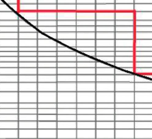
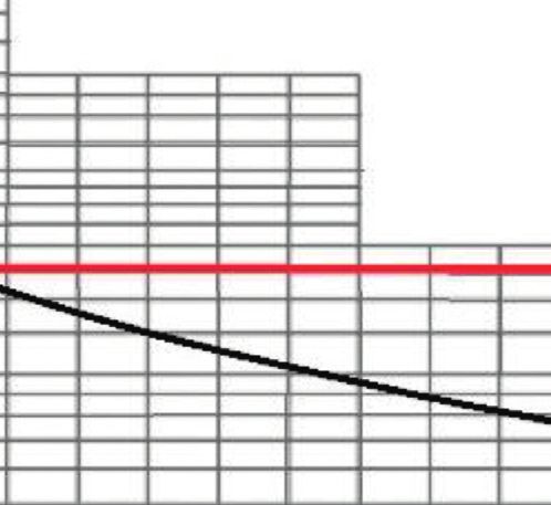
4 International Journal of Optics

 0.5 SD
 Lth
 %
 100
 80
 50
 40
 30

 20

 10
 8
 5
 4
 3
 2

 1 L.sec
 0 2 4 6 8 10 12 14 16 18 20
 Threshold zone
 stopping distance Transition zone

Figure 3: The black line is the luminance reduction curve for CIE 88 : 2004 standard. The length of threshold zone � 0.5 SD, where Lth is 100
%. Threshold zone length � stopping distance (SD). The red lines indicate the target luminance in the zones of tunnels.

 Figure 4: Lseq evaluation diagram of the trial tunnel.

 260
 240
 This curve is only present in UNI 11095 2011
 220
 200
 180
 160
 cd/m2

 140
 120
 100
 80
 60
 40
 20
 (LI = 3.0)
 0m 40m 80m 120m 160 m 200 m 240m 280 m 320 m 360m
Figure 5: The luminance reduction curve, which indicates the minimum required luminance for accomplishing the standards for the trial
tunnel generated by LiteStar 4D software (green curve: CIE 88 : 2004 standar, blue curve: UNI 11095.

simulation, the output report showed that its contrast re- with the target of a qc larger than 1.0 in the threshold zone.
vealing coefficient qc was 0.24, which is less than 0.6. That Through the global searching method with reflector surface
means that the initially designed CBL was insufficient. radius and lamp position acting as the variables, the CBL was
Therefore, the CBL model was optimized using LightTools optimized, as shown in Figure 11(a). Its intensity
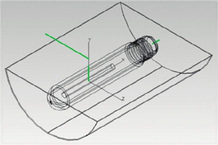
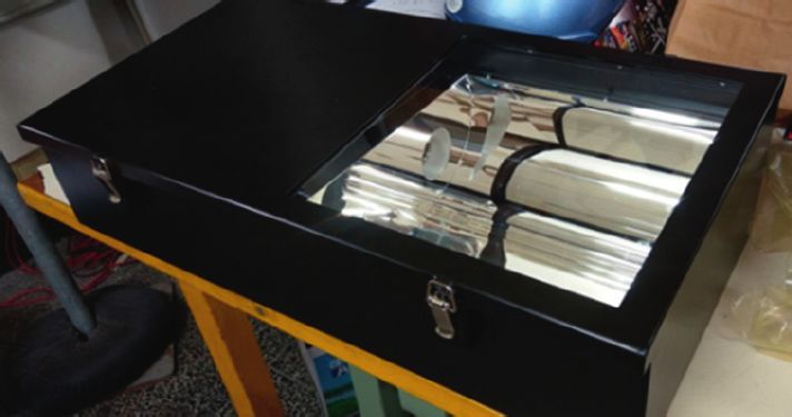
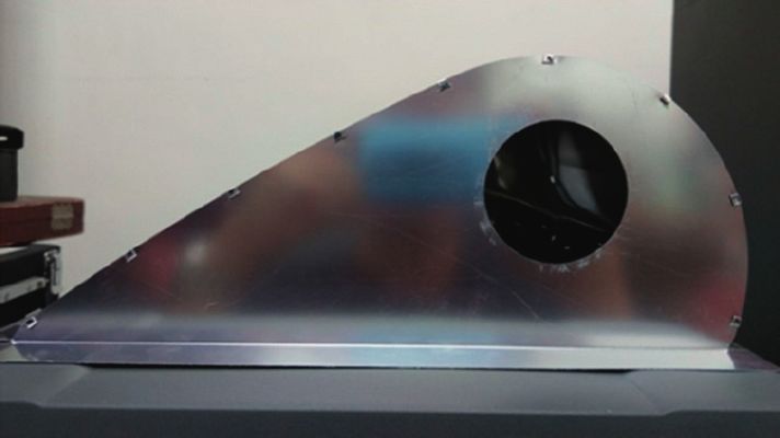
International Journal of Optics 5

 1.6 m 1.6m 1.6m

 Discharging
 Discharging
 Discharging
 T5 (70W)

 400 W
 400 W
 400 W

 lights
 lights
 lights
Figure 6: The tunnel lighting configuration of one 75 W T5 fluorescence light followed by three 400 W discharging lights with sodium lamp
for each traffic lane is repeated from the entry to the end of threshold zone.

 Start

 CBL reflector
 Prototyping End
 optimization
 Optimized CBL
 (light tools)
 Sodium lamp modelling
 (solidworks)

 Optical intensity distribution Intensity distribution
 analysis and far field source measurement of optimized
 file generation of CBL CBR prototype to get its
 New counterbeam light (tracepro) source file
 (CBL) reflector modelling
 (solidworks)

 Input far field source file of Input far field source file of
 optimized CBR model and T5 CBR sample and T5 lights for
 lights for tunnel road tunnel road lighting analysis
 Assembling lamp lighting analysis (litestar 4D)
 and reflector to (litestar 4D)
 proceed optical analysis
 (tracepro)
 No No

 Regulation Regulation
 Arranging CBLs and pass or not? pass or not?
 fluorescent light in
 threshold zone of trial
 tunnel (litestar 4D)

 Yes Yes

 Figure 7: The workflow of optimizing counter beam light to accomplish CIE 88 : 2004 tunnel lighting design.

distribution is shown in Figure 11(b). After optimization, the composed of stainless steel was prototyped for optical
CBL had an R1 of 1000 mm and R2 of 85 mm, and the lamp analysis, as shown in Figure 12. The new CBL fixture in-
position shifted to (74, –65,90) xyz from (49, –36,100) xyz. We stallation with the 400 W sodium lamp with 56,500 lumens is
input the far field source of the optimized CBL into LiteStar shown in Figure 13, which was measured by imaging
4D; the output report showed that its contrast revealing goniophotometers (Radiant Imaging Co. Ltd.) to obtain its
coefficient qc was 1.11, which is above 0.6, indicating that the intensity distribution (Figure 14) and its far field source file,
new design would qualify as a counterbeam light. The tunnel which shows the fixture output power was 37,054 lumens.
road lighting performance evaluation items, including av- Therefore, the efficacy was calculated as 37,054/400 � 93
erage road surface luminance Lav, brightness uniformity Uo, lumen/W. Therefore, after the source file of the optimized
longitudinal brightness uniformity UL, glare factor TI, and qc CBL sample was loaded in LiteStar 4D, the output report
of the initial and final designs of the new CBL are listed in showed that its qc was 1.19 (>0.6), which means that the
Table 1 for comparison. optimized CBL could act as a counterbeam light for tunnel
 To show that the optimized CBL allows the tunnel lighting in practice. The tunnel lighting evaluation items,
lighting to meet CIE 88 : 2004 specifications, a reflector including average road surface luminance Lav, brightness
6 International Journal of Optics

 (a) (b)

Figure 8: (a) Model of ORSAM VIALOX NAV-T SUPER 4Y series 400 W sodium lamp; (b) model of the initial designed reflector of the
proposed counterbeam light.

 Figure 9: The model of the new counterbeam light.

 170 180 170
 160 160
 150 150
 140 140
 130 130
 120 120

 110 110

 100 100

 90 90
 50
 80 80
 100
 70 150 70
 200
 60 60
 250
 50 300 50
 40 350 40
 30 400 30
 20
 10 0 10 20
 Total flux: 32,989 lm
 (a) (b)

Figure 10: (a) The side view of the the new counterbeam light before optimization; R1 and R2 are the surface radius of the light. (b) The
simulated intensity distribution of the new counterbeam light before optimization.

uniformity Uo, longitudinal brightness uniformity UL, glare To demonstrate the advantage of the optimized new
factor TI, and qc of the optimized CBL design and the CBL, the 400 W sodium lamp tunnel light GE17734 (General
measurements from the sample are both listed in Table 2 to Electric Co., Ltd.), broadly used in tunnels, was used to
compare the performance differences. compare their performance in the threshold zone. The
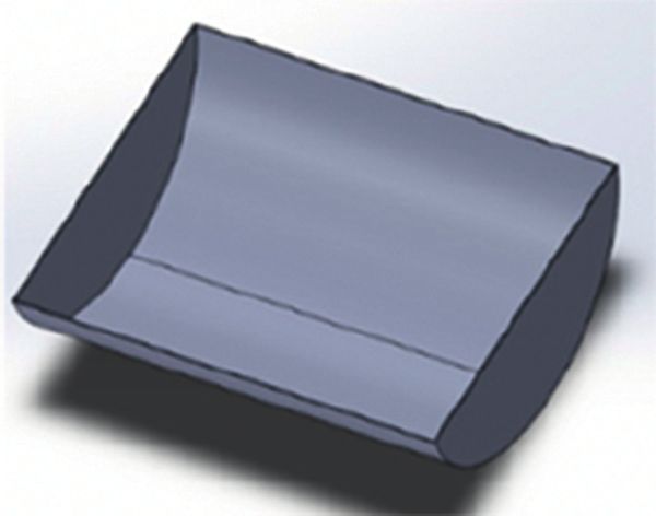
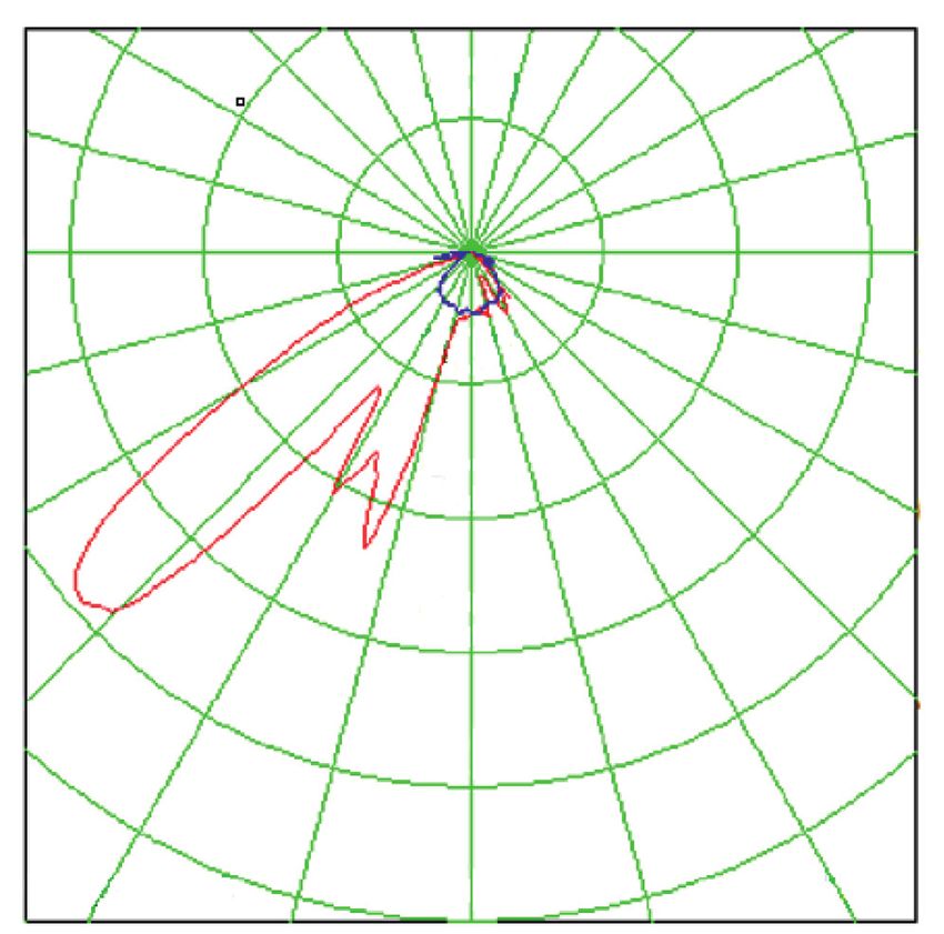
International Journal of Optics 7

 170 180 170
 160 160
 150 150
 140 140
 130 130
 120 120

 110 110

 100 100

 90 90
 50
 80 80
 100
 70 150 70
 200
 60 60
 250
 50 300 50
 40 350 40
 30 400 30
 20
 10 0 10 20
 Total flux: 28,992 lm
 (a) (b)

Figure 11: (a) The side view of the new counterbeam light after optimization; (b) the simulated intensity distribution of the optimized CBL
with a 400 W sodium lamp.

Table 1: The comparison of lighting performance between the 120 135 150 180 150 135 120
initially designed new CBL and the new optimized CBL for the
tunnel threshold zone. 300
 5 5
 CIE
Variable Before optimization After optimization
 standard
Lav (cd/m2) 121 (pass) 123 (pass) >105 90 90
Uo 0.87 (pass) 0.84 (pass) >0.4
UL 0.98 (pass) 0.97 (pass) >0.6 75 300 75
TI 3.6% (pass) 10.41% (pass) 0.6
 600
 60 60

 900

 45 45
 1200

 Gamma 1500 Cd/klm
 30 15 0 15 30
 Total flux: 24,000 lm
 Figure 14: The measured intensity distribution of the optimized
 Figure 12: The prototype of the optimized CBL reflector. CBL with the 400 W sodium lamp.

 measured intensity distribution of the GE17734 (General
 Electric Co., Ltd.) is shown in Figure 15; the output power
 was 36,865 lumens, and the efficacy was calculated as 36,865/
 400 � 92 lumen/W. The lighting performance between the
 optimized new CBL and the GE17734 (General Electric Co.
 Ltd.) in threshold zone of tunnel is compared in Table 3. The
 qc of GE17734 was 0.55, which is below the standard and
 Figure 13: The prototype of the optimized CBL light. much smaller lower than that (1.08) of the optimized CBL.
8 International Journal of Optics

Table 2: Comparison of lighting performance between the opti- physical source model, the new counterbeam can produce an
mized new CBL design and prototype sample measurements in average road surface brightness of 123 cd/m2 (minimum
threshold zone of a tunnel. regulation level � 105 cd/m2), a brightness uniformity Uo of
 Simulation model of Prototyped sample of 0.84 (minimum regulation level � 0.4), a longitudinal
 CIE brightness uniformity UL of 0.97 (minimum regulation
Variable the optimized new the optimized new
 standard
 CBL CBL level � 0.6), a glare factor TI of 10.41% (maximum lev-
Lav el � 15%), and a contrast revealing coefficient qc of 1.19
 123 (pass) 121 (pass) >105 (minimum level � 0.6) in the threshold zone. For demon-
(cd/m2)
Uo 0.84 (pass) 0.88 (pass) >0.4 strating the feasibility of the new CBL in tunnels, a prototype
UL 0.97 (pass) 0.98 (pass) >0.6 was constructed and measured using an imaging gonio-
TI 10.41% (pass) 4.41% (pass) 0.6 created through the measurement of the new CBL sample
 achieved an average road surface brightness Lav of 121 cd/m2
 (minimum regulation level � 105 cd/m2), a brightness uni-
 120 135 150 180 150 135 120
 formity Uo of 0.88 (minimum regulation level � 0.4), a
 150 longitudinal brightness uniformity UL of 0.98 (minimum
 5 5 regulation level � 0.6), a glare factor TI of 4.41% (maximum
 level � 15%), and a contrast revealing coefficient qc of 1.08
 90 90
 (minimum level � 0.6) in the threshold zone. As a result, we
 concluded that the proposed CBL can act as a qualified
 counterbeam light to help tunnel road lighting meet CIE 88 :
 150
 75 75 2004 standards both in simulation and in practice.
 We compared the performance of the GE17734 tunnel
 300 light and the new CBL before and after optimization. The
 60 60
 experimental results (Tables 1–3) showed that the road
 luminance produced by the optimized new CBL is the lowest
 450
 but has the highest qc , which means cars, people, or other
 45
 objects observed on road are the most contrasted, revealed
 45
 600 by the optimized CBL. The results shown in Figures 15,
 10(b), and 11(b) show that the optimized new CBL has a
 750
 weaker light intensity at 40°–45°, meaning light dominates
 Gamma Cd/klm
 the road luminance of drivers, so the optimized new CBL
 30 15 0 15 30
 cannot provide as much luminance as the other fixtures.[20]
 Total flux: 36,865 lm
Figure 15: The measured intensity distribution of the GE17734 Data Availability
CBL (General Electric Co. Ltd.) with the 400 W sodium lamp.
 No data were used to support this study.
Table 3: Comparison of the lighting performance between the
GE17734 sodium tunnel light and the optimized new CBL. Conflicts of Interest
 GE17734 The authors declare that they have no conflicts of interest.
 Prototyped sample of CIE
Parameter sodium tunnel
 the optimized new CBL standard
 light Authors’ Contributions
Lav
 139 (pass) 121 (pass) >105 The authors contributed equally to all parts of this study.
(cd/m2)
Uo 0.82 (pass) 0.88 (pass) >0.4
UL 0.98 (pass) 0.98 (pass) >0.6 References
TI 1.55 % (pass) 4.41% (pass) 0.6 [1] R. H. Simons and A. R. Bean, Lighting Engineering: Applied
 Calculations, Routledge, Abingdon, UK, 2008.
 [2] J. A. Vrooman, Crossing the Threshold: Nabi Depictions of
 Masculinity in Public, Private, and Performative Spaces of Fin-
4. Discussion and Conclusions De-SiècleParis, Dissertation, New York University, New York,
To improve driving safety, a new counterbeam light (CBL) NY, USA, 2017.
 [3] M. Rea, J. Bullough, and Y. Akashi, “Several views of metal
was proposed to meet CIE 88 : 2004 regulations for tunnel
 halide and high-pressure sodium lighting for outdoor ap-
lighting. Using appropriate arrangements of the counter- plications,” Lighting Research & Technology, vol. 41, no. 4,
beam light and conventional fluorescent lights on the ceiling pp. 297–320, 2009.
of a tunnel, we demonstrated that road tunnel lighting with [4] M. S. Rea, A. Bierman, T. McGowan, F. Dickey, and
CIE 88 : 2004 regulations can be accomplished in the LiteStar J. A. Havard, “Eld study comparing the eŒectiveness of metal
4D simulation environment. Based on the simulated halide and highpressure sodium illuminants under mesopic
International Journal of Optics 9

 conditions,” in Proceedings of the Visual Scales: Photometric
 and Colorimetric Aspects, London, UK, March 1997.
 [5] Guide for the Lighting of Road Tunnels and Underpasses, 2nd
 EdCIE 088-1990, 1990.
 [6] J. Da Silva FM, H. M. Bártolo, P Bártolo et al., Challenges for
 Technology Innovation: An Agenda for the Future: Proceedings
 of the International Conference on Sustainable Smart
 Manufacturing (S2M 2016), CRC Press, Lisbon, Portugal,
 2017.
 [7] J. E. M. Teoh, C. K. Chua, Y. Liu, and J. An, “4D printing of
 customised smart sunshade: a conceptual study,” Challenges
 for Technology Innovation: An Agenda for the Future, vol. 105,
 no. 108, pp. 105–108, 2017.
 [8] P. R. Boyce, N. H. Eklund, B. J. Hamilton, and L. D. Bruno,
 “Perceptions of safety at night in different lighting condi-
 tions,” Lighting Research and Technology, vol. 32, no. 2,
 pp. 79–91, 2000.
 [9] W. V. Bommel, Road Lighting: Fundamentals, Technology and
 Application, Springer, Berlin, Germany, 2014.
[10] S. W. Smith and M. S. Rea, “Relationships between office task
 performance and ratings of feelings and task evaluations
 under different light sources and levels,” in Proceedings of
 the19th Session of Commission Internationale de
 l’Éclairage,Kyoto, Japan, 1980.
[11] Y. Akashi, M. S. Rea, and J. D. Bullough, “Driver decision
 making in response to peripheral moving targets under
 mesopic light levels,” Lighting Research & Technology, vol. 39,
 no. 1, pp. 53–67, 2007.
[12] Z. Feng, Y. Luo, and Y. Han, “Design of LED freeform optical
 system for road lighting with high luminance/illuminance
 ratio,” Optics Express, vol. 18, no. 21, pp. 22020–22031, 2010.
[13] Commission Internationale de l’Éclairage, Lighting of Roads
 for Motor and Pedestrian Traffic: CIE 115, CIE, Peter Blattner;
 Switzerland, 2010.
[14] C. Knight, “Field surveys of the effect of lamp spectrum on the
 perception of safety and comfort at night,” Lighting Research
 & Technology, vol. 42, no. 3, pp. 313–329, 2010.
[15] S. Fotios and R. Gibbons, “Road lighting research for drivers
 and pedestrians: the basis of luminance and illuminance
 recommendations,” Lighting Research & Technology, vol. 50,
 no. 1, pp. 154–186, 2018.
[16] A. Scott, “White light-the UK balance sheet,” Lighting Journal,
 vol. 70, no. 1, 2005.
[17] S. Hecht, C. Haig, and A. M. Chase, “The influence of light
 adaptation on subsequent dark adaptation of the eye,” The
 Journal of General Physiology, vol. 20, no. 6, pp. 831–850, 1937.
[18] B. Ahmed, Road Lighting, 2017.
[19] P. R. Boyce, Lighting for Driving: Roads, Vehicles, Signs, and
 Signals, CRC Press, Boca Raton, FL, USA, 2008.
[20] P. R. Boyce and L. D. Bruno, “An evaluation of high pressure
 sodium and metal halide light sources for parking lot light-
 ing,” Journal of the Illuminating Engineering Society, vol. 28,
 no. 2, pp. 16–32, 1999.
You can also read