Investigation on ultrasonic assisted friction stir welding of aluminum/steel dissimilar alloys
←
→
Page content transcription
If your browser does not render page correctly, please read the page content below
High Temperature Materials and Processes 2021; 40: 45–52
Research Article
Kairong Hong, Yong Wang, Jianjun Zhou, Canfeng Zhou*, and Luming Wang
Investigation on ultrasonic assisted friction stir
welding of aluminum/steel dissimilar alloys
https://doi.org/10.1515/htmp-2021-0011
received September 23, 2020; accepted December 11, 2020
1 Introduction
Abstract: The extensive use of light metal material such With the increasingly prominent problems of energy crisis
as aluminum has brought about problems in its joining and environmental pollution, the energy conservation
with steel. However, the weak metallurgical bonding and emission reduction have become the consensus in
between the dissimilar materials and the formation of the manufacturing industries [1,2]. Choosing light alloy
hard and brittle intermetallic compounds (IMCs) lead to materials such as aluminum and magnesium alloys to
unsatisfactory joint strength. Aiming at achieving high- realize the product lightweight is an effective approach
quality joining of aluminum and steel, 6061-T6 alu- to achieve the above aims. Because of the wide applica-
minum and 301L steel alloys were lap joined by ultra- tions of aluminum and steel alloy materials, the aluminum/
sonic assisted friction stir lap welding (UaFSLW) in this steel hybrid welding is an inevitable topic in automobile,
study. The UaFSLW joints were well formed with uniform rail transit, and other equipment manufacturing indus-
flashes and even arc lines. The strong plastic flow of the tries. At present, the welding of aluminum/steel dissimilar
aluminum material driven by the dual effects of mecha- materials can be realized by brazing [3] and fusion welding
nical stirring and ultrasonic vibration inhibited the exces- methods such as arc welding [4], laser welding [5], and
sive growth of the Al–Fe IMCs at the lap interface. Thanks electron beam welding [6]. In recent years, a relatively
to the enhanced metallurgical bonding and the effective
new solid-state welding technique of friction stir welding
control of the layer thickness of IMCs, the tensile load of
(FSW) has been proved to be successfully applied in the
the UaFSLW joint under 1,800 rpm reached 16.5 kN, which
welding of aluminum/steel dissimilar alloys [7,8].
was an increase of 27.9% compared to that of the conven-
The FSW technique has advantages such as low
tional FSLW joint.
welding temperature and small welding distortion because
Keywords: ultrasonic vibration, friction stir lap welding, of its process characteristics [9,10]. During FSW, large
dissimilar materials, tensile property plastic deformation and severe material flow occur in the
weld, and the welded joint is obtained with extremely fine
grains and dense texture [11,12]. The FSW process is proved
to be suitable in the welding of dissimilar materials [13]. In
the friction stir lap welding (FSLW) of aluminum/steel dis-
similar materials without penetrating the upper plate, the
* Corresponding author: Canfeng Zhou, State Key Laboratory of interfacial metallurgical bonding is the main joining mode
Shield Machine and Boring Technology, Department of Technology, [14]. Because of the low solid solubility of iron element in
Zhengzhou, 450001, China; Beijing Institute of Petrochemical aluminum matrix, the bonding of aluminum/steel lap joint
Technology, Beijing Higher Institution Engineering Research Center mainly depends on the layer of Al–Fe intermetallic com-
of Energy Engineering Advanced Joining Technology, Beijing,
pounds (IMCs) formed at the interface [14]. In general, the
102617, China, e-mail: abelms@qq.com
Kairong Hong, Jianjun Zhou: State Key Laboratory of Shield Machine thin layer of IMCs is beneficial to obtain the high strength
and Boring Technology, Department of Technology, Zhengzhou, of the hybrid joint, but the excessively growing thick layer
450001, China of IMCs becomes an obstacle to further enhance the inter-
Yong Wang: Shanghai Institute of Aerospace Chemical Engineering face bonding [15]. When the joint is loaded, the crack is
and Application, Process and Technology Department, Shanghai,
easy to initiate and expand along with the thick brittle layer
201109, China
Luming Wang: Beijing Institute of Petrochemical Technology,
of IMCs, which leads to the decrease in joint strength [16].
Beijing Higher Institution Engineering Research Center of Energy The process parameter optimization is the accessible
Engineering Advanced Joining Technology, Beijing, 102617, China method to control the thickness of the layer of Al–Fe
Open Access. © 2021 Kairong Hong et al., published by De Gruyter. This work is licensed under the Creative Commons Attribution 4.0
International License.
46 Kairong Hong et al.
Table 1: Elemental compositions of alloy materials in weight (wt%)
Alloys Al Mg Si Cu Mn Cr Ni C Fe
6061-T6 Bal. 0.70–0.80 0.40–0.50 0.18 0.08 0.06 — — 0.19
301L steel — — 1.00 — 2.00 16–18 6–8 0.03 Bal.
IMCs. The studies of Boumerzoug and Helal [17] and controlling the formation of Al–Fe IMCs and then obtain-
Ibrahim et al. [18] showed that the relatively low heat ing high-quality hybrid joint. This study is meaningful for
input is the reason for the thin layer of Al–Fe IMCs, which expanding the applications of light alloy materials and the
contributed to the joint strength improvement. In addi- FSW technique in the industries.
tion, introducing zinc element by adding zinc interlayer
or using galvanized steel is proved as an available
method to inhibit the formation of Al–Fe IMCs [19]. In
FSLW, thanks to its high automatic feature, it is feasible 2 Experimental procedure
to apply auxiliary processes in the welding process. It has
been proved that the ultrasonic vibration can effectively In this study, 6061-T6 aluminum alloys and SUS301L aus-
improve the atomic diffusion and the material flow during tenitic stainless steel alloy plates were the base materials
welding [20], and this ultrasonic assisted friction stir to be welded, and the material compositions are pre-
lap welding (UaFSLW) technique has been successfully sented in Table 1. The dimensions of the plates were
applied in the joining of aluminum/magnesium alloys 180 × 150 × 2 mm. The UaFSLW process diagram is shown
[21] and aluminum/titanium alloys [22]. However, the in Figure 1a. The aluminum alloy plate was placed on the
researches on the surface morphology, microstructure, top of the steel plate for lap welding, and the ultrasonic
and mechanical properties of aluminum/steel hybrid joint system consisting of ultrasonic generator and horn was
by UaFSLW are insufficient [23]. applied to the bottom surface of the 301L steel plate. The
In this study, the UaFSLW of 6061-T6 aluminum and ultrasonic frequency was set as 20 kHz, and the ultra-
301L steel alloys was carried out. The strong plastic flow sonic power was 2,000 W. The adopted welding tool is
of the upper aluminum material at the interface was shown in Figure 1b. The shoulder diameter and the pin
achieved by the dual effects of mechanical stirring and length of the welding tool were 15.0 and 1.7 mm, respec-
ultrasonic vibration, which aimed at improving the tively. In this study, the non-threaded pin was used. In
metallurgical bonding of dissimilar material interface, the welding process, the shoulder plunge depth was
Figure 1: Images of (a) UaFSLW process diagram, (b) welding tool geometry, and (c) joint cross-sectional diagram.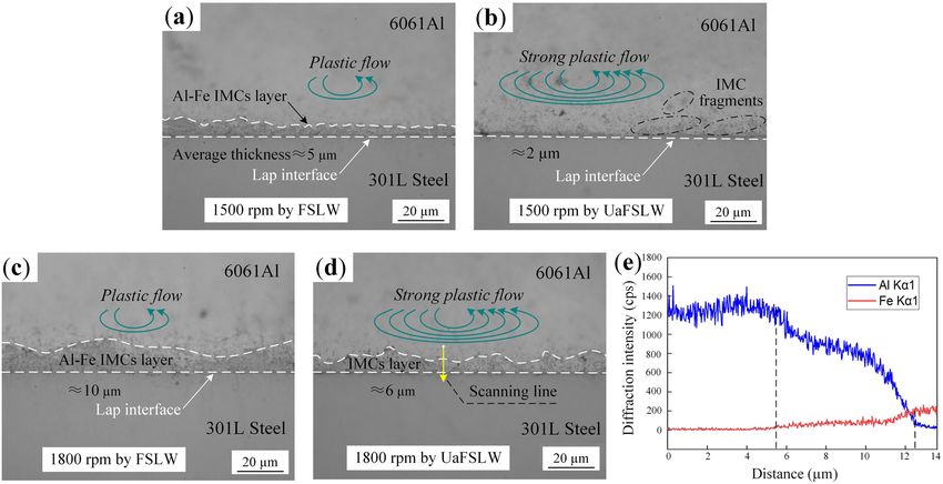
Investigation on ultrasonic assisted FSW of aluminum/steel dissimilar alloys 47
selected as 0.15 mm, so the pin tip has a close distance of and welding time were essential for the hybrid joint
0.15 mm away from the lap interface, as shown in Figure 1c. strength. Therefore, the welding parameter configuration
The distance between the pin tip and the interface has a of high rotational speed and low welding speed was
great influence on the joining of the interface. In this study, selected to ensure stable and reliable welding of hybrid
the displacement control mode of the equipment can ensure joint.
the accuracy of this distance and its uniformity along the The joint surface morphologies are shown in Figure 2.
weld during the welding process. In general, under the selected welding parameters, the
The welding speed was set as 20 mm/min, and the welding heat inputs are adequate, and the sufficient
rotational speeds were selected as 1,500 and 1,800 rpm material flows result in the well-formed joint surfaces
in this study. After welding, the metallographic specimens with clear arc lines. In FSLW joints welded under 1,500
and tensile samples were taken along the direction per- and 1,800 rpm (Figure 2a and c), uneven flashes appear
pendicular to the weld, and the tensile sample was fabri- on the advancing side (AS) and retreating side (RS) of the
cated according to the standard of ISO 4136 [24]. The joint weld. For the UaFSLW process, the flashes are uniform,
microstructure and mechanical properties were observed and the joint surfaces present relatively smooth features
and tested by the Olympus-GX71 optical microscope and (Figure 2b and d). Ultrasonic vibration has the effect of
the Instron-8801 tensile testing machine, respectively. reducing the material flow stress, which is helpful to
The interface elements were analyzed by the scanning improve the joint surface quality [25].
electron microscope (SEM) with an energy dispersive
X-ray spectrometer. After the tensile test, the fracture
morphology of the joint was observed by the SEM.
3.2 Cross sections and microstructures
The typical cross section of UaFSLW joint under 1,800 rpm
is shown in Figure 3a. According to the uneven thermal-
3 Results and discussion mechanical cycles experienced by materials in different
zones, the upper aluminum material in the joint can
3.1 Joint surface morphology be generally divided into shoulder-affected zone, pin-
affected zone (PAZ), thermo-mechanically affected zone,
The joining mechanism of aluminum/steel hybrid joint and heat-affected zone. The joint lap interface remains flat
without tool pin penetration is mainly the interfacial because no penetration of the interface occurs during
metallurgical bonding, and the previous experiments in welding. The lap joining mainly depends on the metallur-
our research group showed that sufficient heat generation gical bonding between dissimilar materials at the lap
Figure 2: Joint surface morphologies obtained under 1,500 rpm of (a) FSLW and (b) UaFSLW; under 1,800 rpm of (c) FSLW and (d) UaFSLW.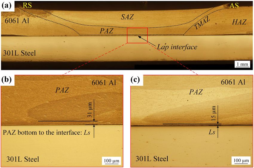
48 Kairong Hong et al.
As shown in the microstructures of the joint in Figure 4,
along with the lap interface, the thickness of the layer of
IMCs is constantly changing, so the thickness values for
different positions are different. In this study, Image J
software was used to measure the thickness of the layer
of IMCs at an interval of 10 µm along with lap interfaces
made by different parameters, and the average of 10
measured values was taken. As shown in Figure 4a and c,
the layers of Al–Fe IMCs with the average thicknesses
of about 5 and 10 μm are observed under 1,500 and
1,800 rpm by FSLW, respectively. This indicates that the
Al–Fe IMCs grow heavily with the increase in heat input,
resulting in the thicker layer of IMCs under 1,800 rpm.
Figure 3: (a) Joint cross section under 1,800 rpm by UaFSLW; PAZ Under UaFSLW, the average thicknesses of the layer of
bottom regions under 1,800 rpm by (b) FSLW and (c) UaFSLW.
IMCs at 1,500 and 1,800 rpm are 2 and 6 μm, respectively,
as shown in Figure 4b and d. The ultrasonic vibration
enhances the material plastic flow of aluminum alloy at
interface below PAZ. During welding, the violent mechan- the PAZ bottom and then restrains the formation of a
ical stirring driven by the rotational tool pushes the plas- continuous thick layer of IMCs at the interface. Besides,
ticized aluminum material to downwards flow to the lap the ultrasonic vibration can smash the layer of IMCs,
interface, which has an active effect on the interfacial forming the separated IMC fragments close to the thin
joining. As shown in Figure 3b and c, the distance Ls layer of IMCs, as shown in Figure 4b.
between the PAZ bottom and the lap interface is 31 μm The assisted ultrasonic can promote the atomic dif-
at 1,800 rpm by FSLW, and the Ls is 15 μm at 1,800 rpm fusion and then thicken the layer of Al–Fe IMC, whereas
by UaFSLW. The ultrasonic vibration significantly pro- in this study, a thinner layer of IMC is observed by
motes the material flow [26], and the enlarged PAZ area UaFSLW both at 1,500 and 1,800 rpm. It is considered
under the pin tip is beneficial to enhancing the interface that the strong plastic flow close to the interface induced
joining. by ultrasonic smashes away the IMC fragments during
Figure 4: Joint interfacial microstructures obtained at 1,500 rpm by (a) FSLW and (b) UaFSLW, at 1,800 rpm by (c) FSLW and (d) UaFSLW;
(e) element analysis by SEM line scanning of interface marked in (d).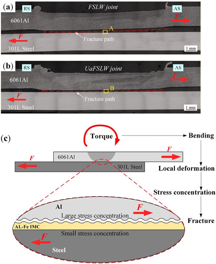
Investigation on ultrasonic assisted FSW of aluminum/steel dissimilar alloys 49
the dynamic formation process of Al–Fe IMCs, and this hybrid joint. Generally, the existence of the layer of IMC
effect is greater than the thickening effect on the layer of is beneficial to the joint strength when the IMC is reason-
IMC caused by the atomic diffusion. The path perpendi- ably thin. However, with the excessive increase in the IMC
cular to the interface of UaFSLW joint is selected for the layer thickness, the joint strength will be deteriorated [14].
element line scanning analysis, as shown in Figure 4d. It The joint-strength improvement rate of UaFSLW to FSLW
is found that the element concentration at the lap inter- at 1,800 rpm is higher than that at 1,500 rpm, which is
face shows a gradual trend because of atomic diffusion related to the effective thinning of the layer of IMCs under
behavior (Figure 4e), and the layer of IMCs is distributed higher welding input condition.
on both sides of the aluminum and steel alloys. Most of The fracture paths of the joints under 1,800 rpm by
the layer of IMC is located on the aluminum side, and the FSLW and UaFSLW are shown in Figure 6a and b. The
thickness of the layer of IMCs at the steel side is relatively upper aluminum plate bears the tensile force from the AS,
thin. Along the selected scanning line, the concentration and the cracks are initiated at the regions of lap interface
of the two elements changed alternately. According to the at the AS where the effective bonding is not formed. The
previous studies of van der Rest et al. [27] and Movahedi cracks propagate rapidly along the layer of IMCs at the
et al. [28], the layer of Al–Fe IMCs at the interface is mainly lap interface to the RS, resulting in the joint failure.
composed of FeAl3 close to the aluminum alloy side and The stress concentration is more likely to occur at the
Fe2Al5 close to the steel alloy side. interface of the hard and brittle layer of IMCs and the
aluminum alloy side, because of the greater difference
of physical properties between these two heterogeneous
materials. In the process of joint fracture, the boundary
3.3 Joint tensile property and fracture between the hard and brittle layer of IMCs and the alu-
behavior minum alloy side is more prone to induce crack propaga-
tion [29]. According to the research by Chen et al. [30],
Three tensile specimens of joint under each welding con- local deformation occurs in the tensile specimen under
dition were used to perform the tensile test, and their the external tensile load, and then the tensile load on the
average tensile loads and standard deviations of mea-
surements were calculated for analyzing. The tensile
loads under different welding conditions are displayed
in Figure 5. The tensile load of the FSLW joint at
1,500 rpm is 15.3 kN. The tensile load of the UaFSLW joint
at 1,500 rpm is 17.4 kN, which is 13.7% higher than that of
the FSLW joint. At 1,800 rpm, the UaFSLW joint has a
tensile load of 16.5 kN, which presents an obvious increase
of 27.9% compared to the 12.9 kN of FSLW joint. In fact,
there is no linear relationship between the thickness of the
layer of Al–Fe IMC and the tensile load of aluminum/steel
Figure 6: Joint fracture paths under 1,800 rpm by (a) FSLW and
Figure 5: Joint tensile properties by different processes. (b) UaFSLW; (c) the typical fracture diagram during the lap-shear test.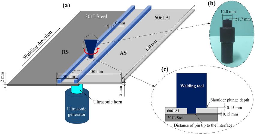
50 Kairong Hong et al.
local deformation of the interface. This effect aggravates
the stress concentration on the interface between the layer
of IMCs and the aluminum alloy. Therefore, the crack
easily initiates and then quickly propagates along this
boundary, thus resulting in the shear fracture of the joint.
As the fracture path is located at the boundary between
the aluminum alloy plate and the Al–Fe IMCs, the fracture
morphologies as shown in Figure 7 are observed on the steel
Figure 7: Joint fracture morphologies in (a) position A in Figure 6(a)
by FSLW, and (b) position B in Figure 6(b) by UaFSLW.
alloy side at positions A and B marked in Figure 6a and b.
Figure 7a shows the fracture morphology of the FSLW joint,
which presents the typical brittle fracture features of the
layer of IMCs is increased. As the typical fracture diagram thick IMCs. The diffusion rate of dissimilar materials at
shown in Figure 6c, during the lap-shear test, the non- the interface of the UaFSLW joint has been enhanced,
parallel and opposite tensile forces provide a torque effect and the adequate element diffusion increases the metallur-
to the lap joint, which drives the bending and then the gical bonding of the interface [31,32]. Therefore, the shear
Figure 8: Diagrams of interfacial joining of dissimilar aluminum/steel alloys: (a) UaFSLW process and (b) FSLW process.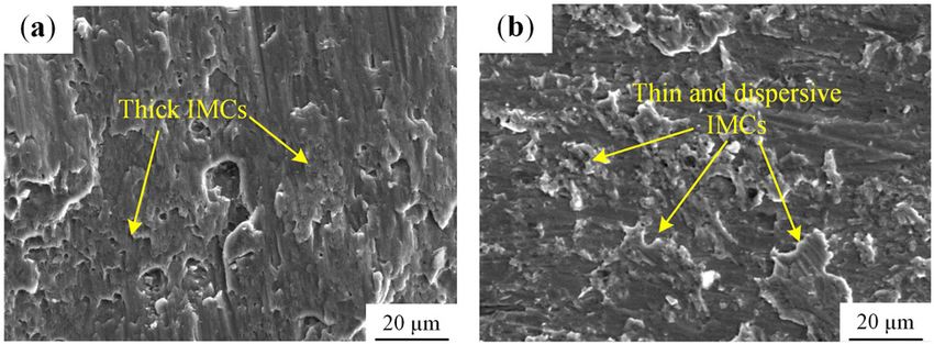
Investigation on ultrasonic assisted FSW of aluminum/steel dissimilar alloys 51
fracture of the UaFSLW joint leaves the thin and dispersive between the PAZ bottom and the interface was shor-
IMCs in its fracture morphology of Figure 7b. This indicates tened compared to that of the conventional FSLW
that the ultrasonic vibration inhabits the formation of con- joint.
tinuous layer of IMCs and also improves the metallurgical (2) The strong plastic flow of the aluminum material on
bonding at the interface. the joint lap interface driven by the dual effects of
mechanical stirring and ultrasonic vibration inhi-
bited the excessive growth of the layer of Al–Fe
IMCs. At 1,800 rpm, the average thickness of the
3.4 Interfacial joining enhancement in continuous layer of IMCs was reduced from 10 μm
aluminum/steel UaFSLW by FSLW to 6 μm by UaFSLW.
(3) In the tensile test, the joints shear fractured along
For the non-penetration FSLW of aluminum/steel alloys, the lap interface. The tensile load of the UaFSLW
the tensile properties of the joint deeply depend on the joint under 1,800 rpm reached 16.5 kN, which was
metallurgical bonding of dissimilar materials at the inter- an increase of 27.9% compared to that of the conven-
face. The material flow close to the lap interface driven by tional FSLW joint.
the rotational pin tip accelerates this effect, which can
produce fine grains and ensure to attain an effective diffu-
sion bonding. However, because the welding temperature Funding information: This work was supported by the
satisfies the thermodynamic condition of Al–Fe metallur- National Natural Science Foundation of China (40776054)
gical reaction, the atomic interactive diffusion leads to the and the Open Project Funds of State Key Laboratory of
formation of Al–Fe IMCs. Generally, the thin and smashed Shield Machine and Boring Technology (SKLST-2018-K01).
IMCs are conducive to improving the joint strength [14],
but the excessively thick layer of IMCs provides a crack Author contribution: The joint study was conducted by
propagation path when the joint is tensile loaded. There- researchers from four institutions. Kairong Hong and
fore, enhancing the material flow and controlling the layer Jianjun Zhou are responsible for the writing of the article,
thickness of Al–Fe IMCs are both important to attain Canfeng Zhou is responsible for the verification and
the high-quality hybrid joint. As shown in Figure 8, the editing of the article, Luming Wang is responsible for
material flow in UaFSLW is strongly enhanced by the the experiment and test, and Yong Wang is responsible
dual effects of mechanical stirring and assisted ultra- for the material characterization and drawing.
sonic vibration. On the contrary, the assisted ultrasonic
also promotes the atomic diffusion. Because of the domi- Conflict of interest: The authors declare that they have no
nant effect of strong plastic flow, some of the thick IMC known competing financial interests or personal relation-
layer at the aluminum side is smashed into IMC frag- ships that could have appeared to influence the work
ments, and the thickness of IMC layer is kept in a thin reported in this paper.
status which is beneficial to the enhancement of alu-
minum/steel hybrid joint strength.
References
4 Conclusions
[1] Kalyankar, V. and G. Chudasama. Influence of electrode tip
diameter on metallurgical and mechanical aspects of spot
To achieve high-quality aluminum/steel hybrid joint,
welded duplex stainless steel. High Temperature Material
6061-T6 aluminum and 301L steel alloys were lap joined
Processes, Vol. 39, 2020, pp. 317–327.
by UaFSLW. Meanwhile, the surface morphology, micro- [2] Liu, Z., K. Yang, and D. Yan. Refill friction stir spot welding of
structure, tensile property, and fracture behavior of the dissimilar 6061/7075 aluminum alloy. High Temperature
hybrid joint were investigated, and the brief conclusions Material Processes, Vol. 38, 2019, pp. 69–75.
can be drawn as follows: [3] He, H., W. Gou, S. Lin, C. Yang, and P. Mendez. GTA weld
brazing a joint of aluminum to stainless steel. Welding journal,
(1) The surface of aluminum/steel UaFSLW joint was
Vol. 98, No. 12, 2019, pp. 365–378.
well formed with uniform flashes and even arc lines. [4] Chang, Q., D. Sun, X. Gu, and H. Li. Microstructures and
The assisted ultrasonic enhanced the fluidity of the mechanical properties of metal inert-gas arc welded joints of
material near the pin tip in UaFSLW, and the distance aluminum alloy and ultrahigh strength steel using Al-Mg and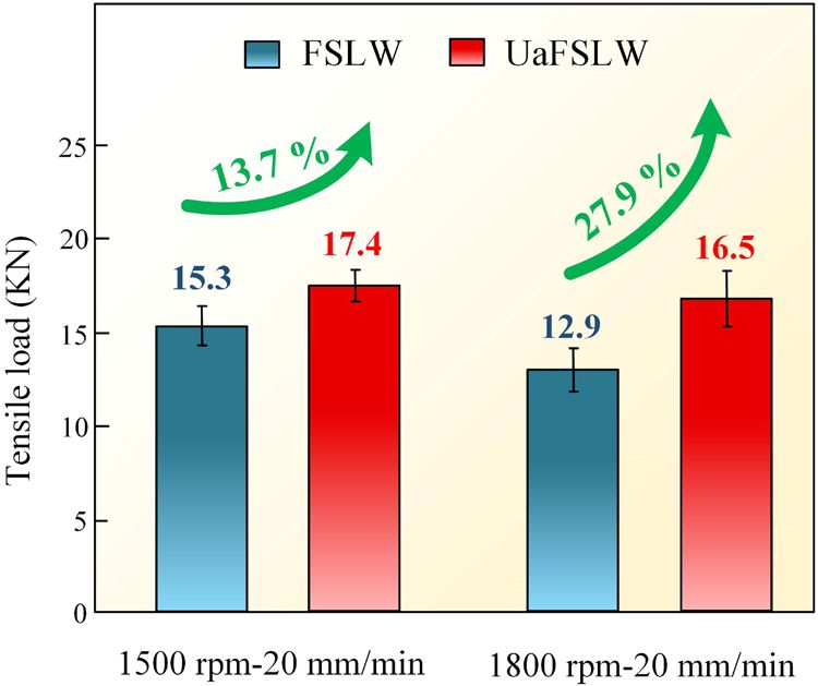
52 Kairong Hong et al.
Al-Cu fillers. Journal of Materials Research, Vol. 32, No. 3, using 5052 Al alloy. Journal of Manufacturing Processes,
2017, pp. 666–676. Vol. 34, 2018, pp. 451–462.
[5] Yuce, C., F. Karpat, and N. Yavuz. Investigations on the [19] Zheng, Q., X. Feng, Y. Shen, G. Huang, and P. Zhao. Dissimilar
microstructure and mechanical properties of laser welded friction stir welding of 6061 Al to 316 stainless steel using Zn
dissimilar galvanized steel-aluminum joints. International as a filler metal. Journal of Alloys and Compounds, Vol. 686,
Journal of Advanced Manufacturing Technology, Vol. 104, 2016, pp. 693–701.
No. 5–8, 2019, pp. 2693–2704. [20] Liu, X., C. Wu, and G. Padhy. Characterization of plastic
[6] Zhang, B., G. Chen, C. Zhang, and J. Ni. Structure and deformation and material flow in ultrasonic vibration
mechanical properties of aluminum alloy/Ag interlayer/steel enhanced friction stir welding. Scripta Materialia, Vol. 102,
non-centered electron beam welded joints. Transactions of 2015, pp. 95–98.
Nonferrous Metals Society of China, Vol. 21, No. 12, 2011, [21] Ji, S., S. Niu, and J. Liu. Dissimilar Al/Mg alloys friction stir lap
pp. 2592–2596. welding with Zn foil assisted by ultrasonic. Journal of
[7] Tanaka, T., M. Nezu, S. Uchida, and T. Hirata. Mechanism of Materials Science and Technology, Vol. 35, No. 8, 2019,
intermetallic compound formation during the dissimilar fric- pp. 1712–1718.
tion stir welding of aluminum and steel. Journal of Materials [22] Ma, Z., Y. Jin, S. Ji, X. Meng, L. Ma, and Q. Li. A general strategy
Science, Vol. 55, No. 7, 2020, pp. 3064–3072. for the reliable joining of Al/Ti dissimilar alloys via ultrasonic
[8] Wang, T., H. Sidhar, R. Mishra, Y. Hovanski, P. Upadhyay, and assisted friction stir welding. Journal of Materials Science and
B. Carlson. Effect of hook characteristics on the fracture Technology, Vol. 35, No. 1, 2019, pp. 94–99.
behaviour of dissimilar friction stir welded aluminium alloy [23] Thoma, M., G. Wagner, S. Benjamin, C. Conrad, and
and mild steel sheets. Science and Technology of Welding and F. Wolfram. Realization of ultrasound enhanced friction stir
Joining, Vol. 24, No. 2, 2019, pp. 178–184. welded Al/Mg- and Al/Steel-joints: Process and robustness,
[9] Ji, S., Q. Wen, and Z. Li. A novel friction stir diffusion bonding mechanical and corrosion properties. Friction Stir Welding and
process using convex-vortex pin tools. Journal of Materials Processing IX, 2017, pp. 179–194.
Science and Technology, Vol. 48, 2020, pp. 23–30. [24] Standardization. ISO 4136, Destructive Tests on Welds in
[10] Xu, W., X. Wu, J. Ma, H. Lu, and Y. Luo. Abnormal fracture of Metallic Materials-Transverse Tensile Test. Geneva, 2001.
7085 high strength aluminum alloy thick plate joint via friction [25] Meng, X., Y. Jin, S. Ji, and D. Yan. Improving friction stir
stir welding. Journal of Materials Research and Technology, weldability of Al/Mg alloys via ultrasonically diminishing pin
Vol. 8, 2019, pp. 6029–6040. adhesion. Journal of Materials Science and Technology,
[11] Meng, X., Y. Huang, J. Cao, J. Shen, and J. Dos Santos. Recent Vol. 34, No. 10, 2018, pp. 1817–1822.
progress on control strategies for inherent issues in friction [26] Amini, S. and M. Amiri. Study of ultrasonic vibrations’ effect on
stir welding. Progress in Materials Science, Vol. 115, 2021, friction stir welding. International Journal of Advanced
100706. Manufacturing Technology, Vol. 73, No. 1–4, 2014,
[12] Li, M., C. Zhang, D. Wang, L. Zhou, D. Wellmann, and Y. Tian. pp. 127–135.
Friction stir spot welding of aluminum and copper: a review. [27] van der Rest, C., P. Jacques, and A. Simar. On the joining of
Materials, Vol. 13, 2020, pp. 1–23. steel and aluminium by means of a new friction melt bonding
[13] Zhou, L., M. Yu, B. Liu, Z. Zhang, S. Liu, X. Song, and H. Zhao. process. Scripta Materialia, Vol. 77, 2014, pp. 25–28.
Microstructure and mechanical properties of Al/steel dissim- [28] Movahedi, M., A. Kokabi, S. Reihani, W. Cheng, and C. Wang.
ilar welds fabricated by friction surfacing assisted friction stir Effect of annealing treatment on joint strength of aluminum/
lap welding. Journal of Materials Research and Technology, steel friction stir lap weld. Materials and Design, Vol. 44, 2013,
Vol. 9, No. 1, 2020, pp. 212–221. pp. 487–492.
[14] Wan, L. and Y. Huang. Friction stir welding of dissimilar alu- [29] Patterson, E., Y. Hovanski, and D. Field. Microstructural char-
minum alloys and steels: a review. International Journal of acterization of friction stir welded aluminum-steel joints.
Advanced Manufacturing Technology, Vol. 99, No. 5–8, 2018, Metallurgical and Materials Transactions A-Physical
pp. 1781–1811. Metallurgy and Materials Science, Vol. 47, No. 6, 2016,
[15] Wan, L. and Y. Huang. Microstructure and mechanical pp. 2815–2829.
properties of al/steel friction stir lap weld. Metals, [30] Chen, Z., S. Yazdanian, and G. Littlefair. Effects of tool posi-
Vol. 7, No. 12, 2017, pp. 1–14. tioning on joint interface microstructure and fracture strength
[16] Haghshenas, M., A. Abdel-Gwad, A. Omran, B. Gokce, of friction stir lap Al-to-steel welds. Journal of Materials
S. Sahraeinejad, and A. Gerlich. Friction stir weld assisted Science, Vol. 48, No. 6, 2013, pp. 2624–2634.
diffusion bonding of 5754 aluminum alloy to coated high [31] Springer, H., A. Szczepaniak, and D. Raabe. On the role of zinc
strength steels. Materials and Design, Vol. 55, 2014, on the formation and growth of intermetallic phases during
pp. 442–449. interdiffusion between steel and aluminium alloys. Acta
[17] Boumerzoug, Z. and Y. Helal. Friction stir welding of dissimilar Materialia, Vol. 96, 2015, pp. 203–211.
materials aluminum Al6061-T6 to ultra low carbon steel. [32] Haghshenas, M., A. Abdel-Gwad, A. Omran, B. Gökce,
Metals, Vol. 7, No. 2, 2017, pp. 1–9. S. Sahraeinejad, and A. Gerlich. Friction stir weld assisted dif-
[18] Ibrahim, A., F. Al-Badour, A. Adesina, and N. Merah. Effect of fusion bonding of 5754 aluminum alloy to coated high
process parameters on microstructural and mechanical pro- strength steels. Materials and Design, Vol. 55, 2014,
perties of friction stir diffusion cladded ASTM A516-70 steel pp. 442–449.You can also read