Multi-objective design optimization of five-phase fractional-slot concentrated-winding surface-mounted permanent-magnet machine
←
→
Page content transcription
If your browser does not render page correctly, please read the page content below
ARCHIVES OF ELECTRICAL ENGINEERING                                                                            VOL. 69(4), pp. 873–889 (2020)

                                                    DOI 10.24425/aee.2020.134636

     Multi-objective design optimization of five-phase
  fractional-slot concentrated-winding surface-mounted
                permanent-magnet machine

                   AMIR NEKOUBINo , JAFAR SOLTANI, MILAD DOWLATSHAH

          Department of Electrical Engineering, Islamic Azad University Khomeinishahr Branch
                                     Khomeinishahr/Isfahan, Iran
          e-mails: nekoubin@yahoo.com, {jafar.soltanizamani/milad.dowlatshahi}@gmail.com

                                   (Received: 06.02.2020, revised: 09.07.2020)

        Abstract: The multi-phase permanent-magnet machines with a fractional-slot concentrated-
        winding (FSCW) are a suitable choice for certain purposes like aircraft, marine, and elec-
        tric vehicles, because of the fault tolerance and high power density capability. The paper
        aims to design, optimize and prototype a five-phase fractional-slot concentrated-winding
        surface-mounted permanent-magnet motor. To optimize the designed multi-phase motor a
        multi-objective optimization technique based on the genetic algorithm method is applied.
        The machine design objectives are to maximize torque density of the motor and maximize
        efficiency then to determine the best choice of the designed machine parameters. Then, the
        two-dimensional Finite Element Method (2D-FEM) is employed to verify the performance
        of the optimized machine. Finally, the optimized machine is prototyped. The paper found
        that the results of the prototyped machine validate the results of theatrical analyses of the
        machine and accurate consideration of the parameters improved the acting of the machine.
        Key words: Finite Element Method, genetic algorithm, optimization, permanent-magnet
        motors

                                                     1. Introduction
    A multi-phase motor has several advantages that make this motor preferable to three-phase
motors. Multiphase motors can operate under fault condition by using the healthy phases [1–5].
The ability to reduce amplitude and boost the frequency of torque ripple, and the minimization
of the stator current per phase without developing the voltage per phase, are the other merits of
multiphase motors [6–8]. By adding a number of phases, it is also feasible to develop the torque
                        © 2020. The Author(s). This is an open-access article distributed under the terms of the Creative Commons Attribution-
                        NonCommercial-NoDerivatives License (CC BY-NC-ND 4.0, https://creativecommons.org/licenses/by-nc-nd/4.0/), which per-
                        mits use, distribution, and reproduction in any medium, provided that the Article is properly cited, the use is non-commercial,
   0                    and no modifications or adaptations are made.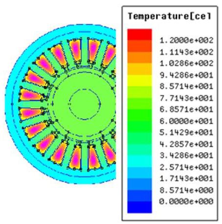
874                         A. Nekoubin, J. Soltani, M. Dowlatshah                      Arch. Elect. Eng.

per RMS ampere for the same volume machine [9, 10]. A multiphase motor is a suitable choice
for use where high reliability is needed such as in aircraft, marine, and electric vehicles [11, 12].
     Permanent magnet synchronous motors with fractional-slot concentrated windings have
higher slot fill factor and lower end windings. In addition, the phase’s mutual inductances are
decreased remarkably. These features enhance the power density of the machine and efficiency.
Further, cogging torque will be diminished [3].
     Sadeghi [13], have introduced an optimal design of a five-phase Halbach permanent-magnet
motor in order to achieve high efficiency, high torque, and high acceleration. The proposed optimal
design is validated through finite-element analysis. It is shown that the optimized multi-phase
permanent magnet machine offers good performance. The effects of different design variables on
torque ripple and torque linearity that should be investigated at the design stage is studied in [14],
it is concluded that torque ripple and torque linearity will be improved by reducing electrical
loading.
     In [15] a five-phase fault-tolerant permanent magnet synchronous machine (PMSM) for
electric vehicles is investigated and, for getting sinusoidal back-electromotive force (EMF), two
typical methods consisting of rotor eccentricity and a Halbach permanent-magnet array are studied
and compared. Also, a PM method is proposed to decrease PM eddy current loss, it is seen that
after PM segmentation, the eddy current loss is reduced significantly. In [16] a FEM model is used
to optimize the radius of the magnet with a mention to the number of poles, rotor size, and magnet
thickness. Features of a permanent-magnet synchronous motor (PMSM) are affected significantly
by the back-electromotive force waveforms in the motor, which are directly dependent on magnet
shape, it is seen that the optimized motor produces very low total harmonic distortion.
     In [17] a new surrogate-assisted multi-objective optimization algorithm is introduced. The
introduced algorithm is employed to an optimal design process of a three-phase IPM motor to
decrease the noise, vibration, and cost. It is seen that, the introduced algorithm can reduce the
design time and effort in IPM motors design using FEM analysis.
     In another study [18], the new design optimization technique of interior permanent magnet
(IPM) synchronous motors based on the Finite Element Method is presented. The presented
optimization technique is implemented to design two IPM motors for an industrial city electric
scooter. It is observed that the simulation results are effective and confirm the proposed technique.
     In [19] a single objective optimization to maximize the torque density for a three- phase
surface-mounted PM motor is applied. In this work, discontinuous variables such as determination
of steel type, permanent-magnet (PM) type, and conductor type are also regarded. It is found that,
the optimized motor produces high torque density. Multi-objective genetic algorithms consist
of two types, non-elitist and elitist [20]. The elitist strategies are completely applicable because
they effectively identify and retain the non-dominated individuals [21]. In [22] simulation of
a 5-phase PM motor with a trapezoidal back-EMF is done. To minimize copper losses a new
control technique is proposed and experimentally verified. It is seen that, the proposed method
has suitable performance for multi phase motors.
     In [23] an IPM motor with a five-phase and fractional-slot stator is investigated. It is seen
that the presented five-phase motor with a fractional slot produces lower torque ripple. In [24]
a design model of a three-phase surface-mounted PM motor is presented. The proposed model
is suitable to be employed for optimal machine design. There is extra attention to the optimized
design of PM motors using a genetic algorithm (GA).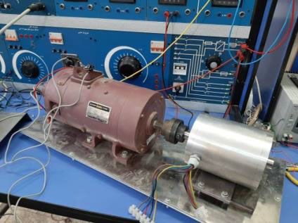
Vol. 69 (2020)                            Multi-objective design optimization                           875

    To promote the performance of multi-phase machine design optimization of the machine is
necessary. In this work, the elitist non-dominated sorting GA (NSGA-II) strategy is employed to
optimize the multi-phase PM machine [25]. Then, the optimized machine is verified by an FEM
model. Finally, the optimized five-phase, surface-mounted PM machine (SPMSM) is prototyped.
Thus, the main contributions of this paper are:
   1) to design and optimize multi-objectively a five-phase FSCW motor based on the NSGA-II
      strategy to maximize torque density of the motor, maximize efficiency and determination
      the best choice of the designed machine parameters;
   2) two-dimensional Finite Element Method (2D-FEM) analysis to attest the acting of the
      optimized motor;
   3) prototyping an FSCW 20-slot/22-pole five-phase, surface-mounted PM machine (SPMSM).
    The analytical design and results are introduced in the second section. In the third section, the
designed machine is optimized multi-objectively. In the fourth section, 2D-FEM analysis of the
optimized machine is done then it is prototyped and experimental results are presented.

                              2. Design of five-phase PMSM motor

    The winding factors and MMF harmonic components of an FSCW motor are mainly indicated
by slot/pole combination. Also, other chrectrestics of the motor like ripple torque, net radial
force and rotor loss, are affected. Hence, determining an optimized slot/pole combination is
fundamental in the motor design steps. The main component of winding factors for possible
slot/pole combination of a 5-phase machine is computed and shown in Table 1.

                             Table 1. Main winding factors of the multi-phase motor

   s/p           2    4          6       8       12       14      16      18          20    22     24
    5       0.58     0.951     0.95     0.58    0.58     0.95    0.95    0.58         –    0.58    0.95
   10            –   0.58      0.80     0.95    0.95     0.80    0.58    0.30         –    0.30    0.58
   15       0.20     0.40      0.58     0.73    0.95     0.98    0.98    0.95         –    0.73    0.58
   20            –    –        0.44     0.58    0.80     0.88    0.95    0.97         –    0.975   0.95
   25       0.12     0.24      0.36     0.47    0.67     0.75    0.81    0.89     0.95     0.96    0.98
   30            –   0.20        –      0.40    0.58     0.65    0.73    0.80         –    0.90    0.95
   35       0.08     0.17      0.26     0.34    0.50     0.58    0.64    0.71         –    0.82    0.86
   40            –    –        0.22      –      0.44     0.51    0.58    0.69         –    0.74    0.80
   45       0.06     0.13      0.20     0.27    0.40     0.41    0.52    0.58         –    0.68    0.73
   50            –   0.12      0.18     0.24    0.36     0.41    0.47    0.48     0.58     0.62    0.67

   From the results of Table 1 it can be concluded that 20-slot/22-pole combination has the
highest winding factors among other combinations.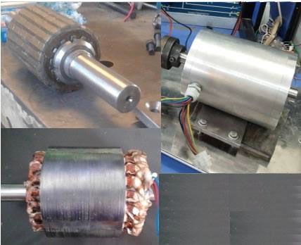
876                         A. Nekoubin, J. Soltani, M. Dowlatshah                       Arch. Elect. Eng.

    Double layer windings compared with single layer windings have shorter end windings, more
sinusoidal back-EMF, lower rotor losses because of lower magnetic motive force (MMF) space
harmonic and support many slot/pole combinations [3]. According to all the conditions connected
to a fraction slot winding, double layer FSCW 20-slot/22-pole configuration is considered for
designing a five-phase surface-mounted permanent-magnet machine.
    The initial design of the machine according to the correlation between the machine design
specification and the machine geometrical dimensions based on an analytical method is presented
in this part. The geometry of a permanent-magnet motor is mainly determined on the basis of
torque capability requirements. Other criteria affecting the motor dimensioning are the motor
speed rating, and the minimum rotor critical speed. The desired output power of the motor to
be designed is 1100 W at a base speed of 1500 rpm; thus, the rated torque to be reached is
about 7 Nm.
    The first harmonic of the air gap magnetic flux density Bg1 is [26]:

                                         ∫
                                        0.5αiπ
                                   1                               2        αi π
                           Bg1   =               Bg cos α dα =       Bg sin      ,                   (1)
                                   π                               π         2
                                       −0.5αiπ

where: the coefficient αi is named the pole-shoe arc-to-pole-pitch ratio, Bg is the magnetic flux
density of the air gap.
   The rotor outer diameter Rro is calculated as:

                                                         pBgNi
                                                 Rro =         ,                                     (2)
                                                          πσ
where: p is the number of magnet pole pairs, σ is shear stress, Ni stands for the coils’ ampere-turns
and g is the air-gap thickness.
   The air-gap thickness g for p > 1 (number of magnet pole pairs) should be expressed as [26]:

                                          g = 0.18 + 0.006P0.4,                                      (3)

where P is the output power in watt.
   The peak value of the stator (armature) line current density (A/m) or specific electric loading
Am is given by [26]
                                   √            √           √
                               2m 2N Ia       m 2N Ia     m 2N Ja Sa
                        Am =              =             =              ,                       (4)
                                  πDsin          pτ             pτ
where: Dsin is the stator inner diameter, Ja is the current density in the stator (armature) conductors
(A/m2 ), N is the number of armature turns per phase, Ia is the armature current, τ is the pole
pitch, s a is the cross section of armature conductors including parallel wires and m is the number
of parallel paths.
    The physical size of the motor is formulated as a function of the flux density in the air gap
Bg , in the tooth Bt , and in the back iron Bbi . The back-iron thickness hbi is calculated as [26]:

                                                     Bg πDsin
                                             hbi =            .                                      (5)
                                                     2Bbi 2p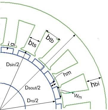
Vol. 69 (2020) Multi-objective design optimization 877
The tooth height ht is expressed as a function of external diameter Dsout and internal diameter
Dsin as [26]:
Dsout − Dsin
ht = − hbi . (6)
2
Then the tooth width btb is calculated as [26]:
Bg πDsin L
btb = , (7)
Bt QL
where Q is the number of slots, and L is the stack length.
The slot area Sslot is expressed as [26]:
π [ ]
Sslot = (Dsout − 2hbi ) 2 − Dsin
2
− btb ht . (8)
4Q
The number of turns per coil Ncoil for double-layer winding is given by [26]
1 Jc Sslot Ks f
Ncoil = , (9)
2 IR
where: Sslot is the slot area, Ks f is the slot fill factor, IR is the rms phase current.
The volume of all permanent magnets used in a motor calculated by Equation (10), [26].
VM = 2ph M w M l M , (10)
where h M , w M and l M are the height, width, and length of the PM, respectively.
Considering all the flux generated by the permanent magnet is linked with a stator winding,
the fundamental component of back EMF can be calculated by [26]
2 πD
E = 4.44 f Nc B1 Kw1 L, (11)
π p
where: B1 is the first harmonic of the air gap magnetic flux density, f is the frequency, Nc is the
number of turns per phase and Kw1 is the fundamental winding factor, D is the stator bore, L is
the active length of the motor.
The electromagnetic torque is formulated as [3]:
Selm cos ψ π
Td = = Kw Dsin
2
LBg Am cos ψ, (12)
2πns 4
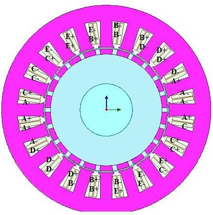
where Kw is the winding factor. Fig. 1(a) indicates a cross-section of a PM motor with its
geometrical dimensions.
Some of more significant considerations for the design of an electric motor are the current
density restriction, and the motor temperature limitation, maximum flux densities in the stator
teeth and back iron. With regard to the motor concerns and the design considerations, the initial
design of the motor, according to the analytical relations, was investigated. The designed five-
phase motor with 20-slots and 22-poles is shown in Fig. 1(b).
The motor parameters derived from the analysis are shown in Table 2 and the analytical results
are listed in Table 3.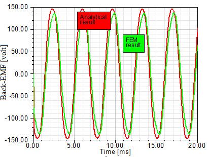
878                              A. Nekoubin, J. Soltani, M. Dowlatshah                 Arch. Elect. Eng.

                           (a)                                               (b)
Fig. 1. Cross-section of the designed SPMSM (a); the five-phase SPMSM motor with 20-slots/22-poles (b)

                                    Table 2. Machine key design parameters

                   Quantity                          Values of the five-phase motor    Symbol
            Outer diameter of stator                          128.324 (mm)              Dsout
                 Active length                                94.895 (mm)                 L
                     Air gap                                    0.7 (mm)                  g
              Thickness of magnet                              3.56 (mm)                 hm
      Pole arc to pole pitch ratio (percent)                      82%                     ya
            Inner diameter of stator                          74.428 (mm)                Dsin
                   Slot depth                                 15.431 (mm)                 ht
          Stator back iron depth (mm)                             13.15                  hbi
                Type of magnet                                   NdFe35                   –
                  Type of steel                                M19_24 G                   –
              Terminal resistance                             2.495 (ohm)                 R
                 Wire diamete                                 0.5106 (mm)                 d
        Number of conductors per slot                              198                    N
               Parallel branches                                    2                     m

    As we can see from Table 3, the values of the electric loading and armature current density
of the machine are reasonable. It can be concluded that the results of the initial design of the
machine are in an acceptable range. But the total loss is high and the efficiency of the machine
is under 90 percent. Also, the total mass of the machine is relatively high. In the next part for
developing the performance of the machine a multi-objective optimization will be done.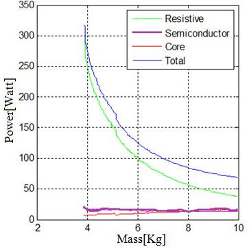
Vol. 69 (2020)                             Multi-objective design optimization                    879

                                           Table 3. Initial design results

                        Quantity                                 Values of the five-phase motor
                  Maximum back-EMF                                            146.583 (V)
                  Armature thermal load                               112.736 (A^2/mm^3)
                  Linear current density                                 17.5201 (A/mm)
                 Armature current density                               6.72008 (A/mm^2)
                      Iron-core loss                                          27.837 (W)
                  Armature copper loss                                       120.268 (W)
                        Total loss                                           148.091 (W)
                      Output power                                           1100.21 (W)
                       Input power                                           1248.552 (W)
                        Efficiency                                               88.10 (%)
                      Rated torque                                           7.00416 (N·m)
                       Total mass                                              6.75 (kg)
                     Torque density                                              1.037

                                              3. Optimization

    In this section optimization for the designed five-phase motor is done. The design variables
are determined as the magnet depth, air gap length, pole arc to pole pitch ratio, active length, depth
of tooth base, and the depth of stator back-iron. The variation range of the variables are shown
in Table 4. The first purpose of this paper is to maximize torque density considering constraints.
The objective function is:
                                                    Tem
                                     G1 (d) =                  ,                                  (13)
                                               Ws + Wm + Wc
where: d is the vector of variables to be explored, Tem is the electromagnetic torque, Ws , Wm , Wc
are the weight of used steel, magnets and copper, respectively.
    The second objective is to maximize the efficiency subject to considering constraints.

                                                             P
                                       G2 (d) =                       ,                           (14)
                                                     Ps + Pr + Pc + P

where: Pc indicates the core loss which consists of hysteresis loss (Ph ) and eddy current loss
(Pedd ), Pr denotes the resistive loss in the machine and Ps is the semiconductor loss.
    Due to guarantee the suitable performance of the machine, a few of the constraints on the
design are considered. The first limitation is concerned to the machine geometry, it is interested
to determine the length of the teeth acceptable compared to their width. The current density of
the wire is the second constraint that should not increase from a reasonable value. The third
constraint is the permanent magnet demagnetization. The tooth flux density must be lower than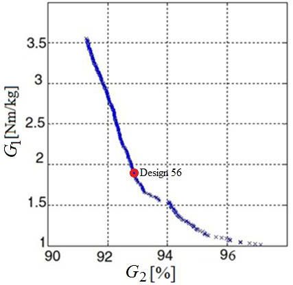
880 A. Nekoubin, J. Soltani, M. Dowlatshah Arch. Elect. Eng.
the maximum allowable value of the tooth flux density, this is the forth constraint and the same
constraints must be considered for the stator back iron and the rotor. All of the constraint functions
is introduced as:
∏N
M (d) = Mi (D), (15)
i=1
where M (d) is the constriants function and N is the number of constraints. M is equal to 1 when
all constraints are satisfied and it is equal to 0 as one or more constraints fail to be satisfied.
Actually, it is interested to investigate the tradeoff between torque density and efficiency. The
fitness function is defined as:
G (d)
G(d) = M (d),
1
G2 (d)
(16)
where G1 (d) and G2 (d) are indicated by (13) as well as (14), respectively, and M (d) is defined by
(15). Multi-objective evolutionary algorithms (EAs) that employ traditional genetic algorithms
have been abolished because of their:
1) high computational complexity of non-dominated sorting (where the number of objectives
and the population size are);
2) non-elitism approach;
3) the need for specifying a sharing parameter.
In this paper, a non-dominated sorting-based multi-objective EA (MOEA), called non-
dominated sorting genetic algorithm II (NSGA-II) is used, which moderates all the above three
drawbacks. Simulation results on optimization show that the employed NSGA-II is able to find
much better spread of solutions and better convergence near the true Pareto-optimal front. The
optimization is planned for a population size of 250 over 250 generations. The first step for the
optimization is determining design variables and a range for each of them. These ranges are
specified depend on the design specifications and the motor design constraints. Table 4 depicts
the design variables and ranges for this study.
Table 4. Design variables ranges
Quantity Min Max Symbol
Air gap (mm) 0.3 1 g
Magnet depth (mm) 1 5 hm
Pole arc to pole pitch ratio (percent) 40 100 ya
Active length (mm) 20 120 L
Stator back iron depth (mm) 5 30 hbi
Depth of tooth base (mm) 1 25 ht
In the multi-objective technique, all objective functions are optimized at the same time by
determining the design parameters. The Genetic Algorithm technique is effectively employed as
a powerful method for multi-objective optimization of permanent-magnet machines [27]. This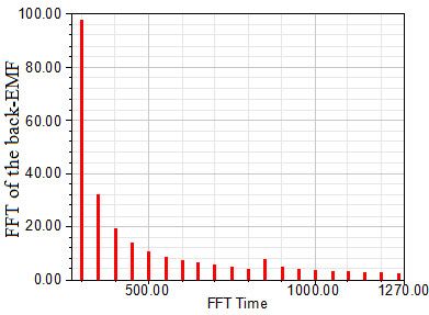
Vol. 69 (2020)                         Multi-objective design optimization                             881

algorithm consists of initialization, evaluation, selection, cross-over and mutation. An initial
population is produced randomly or according to expert data in the first step.
     Over an optimization objective function, the fitness of each individual in this population
is inspected. For choosing the parents a selection method is employed to the initial population.
A new population is generated by applying the genetic operators to parents. To avoid ignoring elite
individuals in each population elitist rules are also used. This method is repeated until optimal
parameter quantities are reached. In this paper the objectives are to maximize torque density and
the efficiency of the machine, subject to considering constraints.

3.1. Optimization results
    The multi-objective optimization is used to optimize two objectives at the same time. This
causes a set of so-called Pareto optimal results. Fig. 2(a) shows the result of the multi-objective
optimization between torque density and efficiency for the five-phase motor.

                          (a)                                                    (b)
Fig. 2. Pareto-optimal front result for the five-phase motor (a); power loss components versus mass for the
                                              five-phase motor (b)

    For the designed five phase motor, it is observed that, as the torque torque density changes
from 3.5 to 1 the efficiency increases from 90 to 96 percent. Loss components versus mass are
shown in Fig. 2(b) Stator resistance loss decreases remarkably with mass but, semiconductor loss
and core loss are approximately steady as mass changes. In fact, the conductor mass goes up as
the total mass increases. Based on requirements and limitations in motor applications one of the
optimized designs must be selected. Due to aircraft and electric vehicle applications, torque and
mass of the used electrical motor are two main factors, the 56th design was selected for next
studies. The optimized variables and the design results of the 56th design of the pareto-optimal
front are listed in Table 5 and Table 6, respectively. It is observed that the specific electric loading
and the armature current density of the selected design are in acceptable values. The core loss
and armature copper loss are decreased. Also, it is viewed that the efficiency is increased by
about five percent and the torque density is increased by about thirty percent. Therefore, proper
multi-objective optimization is applied.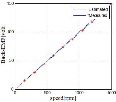
882                          A. Nekoubin, J. Soltani, M. Dowlatshah                             Arch. Elect. Eng.

                                Table 5. The optimazed design variables

                       Quantity                                  Value                   Symbol
                     Air gap (mm)                                0.545                     g
                  Magnet depth (mm)                              0.315                    hm
          Pole arc to pole pitch ratio (percent)                   85                      ya
                  Active length (mm)                             91.15                     L
              Stator back iron depth (mm)                        11.41                    hbi
               Depth of tooth base (mm)                          13.19                     ht

                                    Table 6. Pareto-optimal front results

                       Quantity                              Values of the five-phase motor
                Maximum back-EMF                                         148.146 (V)
               Armature thermal load                                 99.819 (A2 /mm3 )
                Linear current density                                  19.812 (kA/m)
              Armature current density                                  5.021 (A/mm2 )
                    Iron-core loss                                       11.8379 (W)
                Armature copper loss                                     72.268 (W)
               Outer diameter of stator                                  120.32 (mm)
               Inner diameter of stator                                  72.42 (mm)
            Number of conductors per slot                                      180
                   Parallel branches                                            2
                       Total loss                                        84.578 (W)
                    Output power                                         1100.11 (W)
                     Input power                                        1184.578 (W)
                      Efficiency                                              92.86 (%)
                     Rated torque                                        7.141 (Nm)
                      Total mass                                            5.151 (kg)
                    Torque density                                            1.359

                       4. Numerical modelling of PMSM motor

    The initial design was performed depending on the analytical equations of the electric machine.
In this section a finite-element analysis was employed to verify the model accuracy. A comparison
Vol. 69 (2020) Multi-objective design optimization 883
was done to verify the optimized variables of the machine concluded from the analytical method
and the FEM model.
4.1. Back-EMF
Transient simulation with MAXWELL-2D is done to calculate back-emf of the optimized
motor when the rotor has its rated speed (1500 rpm). As we can see in Fig. 3, due to slot/pole
combination, it was selected properly, the back-EMF waveforms are completely sinusoidal and
their harmonics are eliminated remarkably. The results show acceptable agreement between the
analytical calculations and FEM method. The FFT analysis of the back-EMF waveforms of the
five-phase motor is shown in Fig. 4. It is observed that the back-EMF of the five-phase motor has
satisfactory harmonics analysis.
Fig. 3. Back-EMF calculations at rated speed
Fig. 4. FFT analysis of the back-EMF waveform of the five-phase motor884 A. Nekoubin, J. Soltani, M. Dowlatshah Arch. Elect. Eng.
4.2. Electromagnetic torque
The electromagnetic torque of a five-phase motor during a full-load condition for the analytical
design and the FEA method is shown in Fig. 5, the average torque of the five phase motor is 7.2 Nm.
It should be considered that the analytical design method only implements the fundamental of
the air-gap magnetic field and thus the resulting torque is an average value without pulsations.
However, this average agrees with the average value of the FEA method.
7.46
7.25
(Moving1.Torque) [NewtonMeter]
Analytical
Design(red
7.00 line)
FEM
Deisgn(blue
line)
6.75
6.50
6.25
1.02 1.50 2.00 2.50 3.00
Time [ms]
Fig. 5. Electromagnetic torque of the five-phase SPMSM motor
Finite element analysis results are employed to validate the optimized motor. The results are
depicted in Table 7. From the results, it is understood that the inaccuracy is below 5% and it is
concluded that the FEM method confirms the accuracy of the optimized design.
Table 7. Optimum design results for five- phase motor
Quantity Analytical FEM
Output power (W) 1100.11 1100.05
Output torque (Nm) 7.141 7.014
Total loss (W) 84.578 88.231
Total mass (kg) 5.151 5.672
Machine efficiency 92.86% 92.57%
Torque density 1.359 1.234
4.3. Thermal analysis of the designed machine
It is essential to have enough information about the temperature distribution in the motor.
An FEA is a reliable thermal analysis tool for electrical motors. The thermal distribution of theVol. 69 (2020) Multi-objective design optimization 885
optimized five-phase motor is shown Fig. 6. For the designed SPMSM operation, the main heat
sources are the stator copper loss and the stator core loss. As we can see from Table 8 all parts of
the optimized motor are operating in acceptable temperature.
Fig. 6. The thermal distribution of the optimized five- phase motor
Table 8. The result of thermal analysis of the designed five- phase motor
Part Temp [◦ C]
Rotor 98.3
Winding slot 119.7
Stator yoke 105.9
Stator teeth 107.5
4.4. Prototype and experiment
The optimized FSCW five-phase, surface-mounted PM machine with 20-slot/22-pole is pro-
totyped and tested for validation. The rotor with 22 poles, the stator core with the windings and
the prototyped machine are shown in Fig. 7.
At first, the winding inductance of each machine phase is measured by using a LCR meter.
In addition, DC phase resistance is measured. The maesurments compared to the resistance and
inductance values are calculated during the intial design of the machine (Table 9). The higher
value of the resistance can be observed due to the fact that the prototype machine has larger
end-windings than expected and the measured phase inductance is 5 percent lower than expected.
To measure the back-EMF, the machine phase windings are connected in star form and the
test is done for a number of speeds, ranging from 0 to 1500 rpm. Fig. 8 shows the experimental886 A. Nekoubin, J. Soltani, M. Dowlatshah Arch. Elect. Eng.
Fig. 7. Rotor core, stator core with windings and prototyped machine
Table 9. Comparison between measured and estimatated resistance and inductance
Part Measured Estimated
Resistance (ohm) 2.156 1.99
Inductance (mH) 14.126 14.834
setup. A comparison between the estimated and measured back-EMF at different speed is shown
in Fig. 9(a). It can be seen that the obtained results are highly reasonable. The small differences
between the estimated and measured results are due to a number of reasons, like different
characteristics of the used PM and iron materials as well as manufacturing tolerances.
Fig. 8. Experimental setup
The experimental back-EMF of the prototyped machine at a rated speed of 1500 rpm is shown
in Fig. 9(b). It could be concluded that the value and waveform of lab the measured back-EMF of
the prototype five-phase machine are approximately the same as theoretical measurements.Vol. 69 (2020) Multi-objective design optimization 887
(a) (b)
Fig. 9. Comparison between estimated and measured back-EMF at different (a); the experimental back-EMF
of the prototyped machine at a rated speed of 1500 rpm (b)
5. Conclusions
In this paper, a five-phase surface-mounted permanent-magnet motor was designed and op-
timized, also the advantages of a multi-phase motor over a three-phase motor were investigated.
To optimize the designed motors, a multi-objective optimization based on a genetic algorithm
method was used. To evaluate the performance of the optimized machine, the 2D-FEM was ap-
plied. It was concluded that the analytical model confirms the accuracy of the design, also it was
shown that a multi-phase motor can produce higher electromagnetic torque and back-EMF and
lower cogging torque compared with the three-phase motor.
References
[1] Gang L., Bo R., Zi Q., Design guidelines for fractional slot multi-phase modular permanent magnet
machines, IET Electric Power Application, vol. 11, no. 6, pp. 1023–1031 (2017).
[2] Listwan J., Analysis of fault states in drive systems with multi-phase induction motors, Archives of
Electrical Engineering, vol. 68, no. 4, pp. 817–830 (2019).
[3] EL-Refaie A.M., Fractional-Slot Concentrated-Windings Synchronous Permanent Magnet Machines:
Opportunities and Challenges, IEEE Transactions on Industrial Electronics, vol. 57, no. 1, pp. 107–121
(2010).
[4] Caramia R., Piotuch P., Pałka R., Multi-objective FEM based optimization of BLDC motor using Matlab
and Maxwell scripting capabilities, Archives of Electrical Engineering, vol. 63, no. 1, pp. 115–124
(2014).
[5] Sarikhani A., Mohammed O., Multiobjective design optimization of coupled PM synchronous motor-
drive using physics-based modeling approach, IEEE Transactions on Magnetics, vol. 47, no. 5,
pp. 1266–1269 (2011).
[6] Cros J., Viarouge P., Synthesis of high performance PM motors with concentrated windings, IEEE
Transactions on Energy Conversion, vol. 17, no. 2, pp. 248–253 (2002).
[7] Zhu Z., Howe D., Instantaneous magnetic field distribution in brushless permanent magnet motors,
part III: Effect of stator slotting, IEEE Transactions on Magnetics, vol. 29, no. 1, pp. 143–151 (1993).888 A. Nekoubin, J. Soltani, M. Dowlatshah Arch. Elect. Eng.
[8] Proca A., Keyhani A., El-Antably A., Lu W., Dai M., Analytical model for permanent magnet motors
with surface mounted magnets, IEEE Transactions on Energy Conversion, vol. 18, no. 3, pp. 386–391
(2003).
[9] Refaie A.M., Jahns T.M., Novotny D.W., Analysis of surface permanent magnet machines with frac-
tional slot concentrated windings, IEEE Transactions on Energy Conversion, vol. 21, no. 1, pp. 34–43
(2006).
[10] EL-Refaie A.M., Jahns M., Optimal flux weakening in surface PM machines using fractional slot
concentrated windings, IEEE Transactions on Industry Applications, vol. 41, no. 3, pp. 790–800
(2005).
[11] Chen J., Zhu Z., Winding configurations and optimal stator and rotor pole combination of flux-switching
PM brushless AC machines, IEEE Transactions on Energy Conversion, vol. 25, no. 2, pp. 293–302
(2010).
[12] Yong K., Hong C., Chang K., Pan S., A back EMF optimization of double layered large-scale BLDC mo-
tor by using hybrid optimization method, IEEE Transactions on Magnetics, vol. 47, no. 5, pp. 998–1001
(2011).
[13] Sadeghi S., Parsa L., Multiobjective Design Optimization of Five-Phase Halbach Array Permanent-
Magnet Machine, IEEE Transactions on Magnetics, vol. 47, no. 6, pp. 828–837 (2011).
[14] Islam S., Islam R., Sebastian T., Experimental Verification of Design Techniques of Permanent-Magnet
Synchronous Motors for Low-Torque-Ripple Applications, IEEE Transactions on Industry Applications,
vol. 47, no. 1, pp. 28–37 (2011).
[15] Li Y., Xing J., Wang T., Lu Y., Programmable Design of Magnet Shape for Permanent Magnet
Synchronous Motors With Sinusoidal Back EMF Waveforms, IEEE Transactions on Magnetics, vol. 44,
no. 9, pp. 18–25 (2008).
[16] Parasiliti F., Villani M., Lucidi S., Finite-Element-Based Multiobjective Design Optimization Proce-
dure of Interior Permanent Magnet Synchronous Motors for Wide Constant-Power Region Operation,
IEEE Transactions on Magnetics, vol. 6, no. 10, pp. 211–219 (2012).
[17] Lim D., Kyung Y., Sang J., Optimal Design of an Interior Permanent Magnet Synchronous Motor
by Using a New Surrogate-Assisted Multi-Objective Optimization, IEEE Transactions on Magnetics,
vol. 51, no. 11, pp. 11–19 (2015).
[18] Parsa L., Toliyat A., Five-Phase Interior Permanent-Magnet Motors With Low Torque Pulsation, IEEE
Transactions on Industry Applications, vol. 43, no. 1, pp. 128–137 (2007).
[19] Cassimere B., Sudhoff D., Population based design of surfacemounted permanent magnet synchronous
machines, IEEE Transactions on Energy Conversion, vol. 24, no. 2, pp. 41–48 (2009).
[20] Deb K., Multi-Objective Optimization Using Evolutionary Algorithms, Wiley (2001).
[21] Kim J., Cho D., Jung H., Lee C., Niching genetic algorithm adopting restricted ompetition selection
combined with pattern search method, IEEE Transactions on Magnetics, vol. 38, no. 2, pp. 1001–1004
(2002).
[22] Fatima M., Seifeddine B., Analysis, simulation and experimental strategies of 5-phase permanent
magnet motor control, Archives of Electrical Engineering, vol. 68, no. 3, pp. 629–641 (2019).
[23] Zheng P., Sui Y., Zhenxing F., Investigation of a Five-Phase 20-Slot/18-Pole PMSM for Electric Vehi-
cles, 17th International Conference on Electrical Machines and Systems, Hangzhou, China, pp. 22–25
(2014).
[24] Sudhoff D., Cale J., Cassimere N., Swinney D., Genetic algorithm design of a permanent magnet
synchronous machine, in Proc. IEEE International Conference Electrical Machines and Drives, New
York, US, pp. 1011–1019 (2005).Vol. 69 (2020) Multi-objective design optimization 889
[25] Sudhoff D., Lee Y., Energy Systems Analysis Consortium (ESAC) Genetic Optimization System Engi-
neering Tool (GOSET) Version 1.05 Manual, School of Electrical and Computer Engineering, Purdue
Univ., West Lafayette (2003).
[26] Hendershot M., Miller J., Design of Brushless Permanent Magnet Motors, Monographs in Electrical
and Electronic Engineering, Oxford University Press (1995).
[27] Di Barba P., Mognaschi M., Venini P., Wiak S., Biogeography-inspired multi-objective optimization
for helping MEMS synthesis, Archives of Electrical Engineering, vol. 66, no. 3, pp. 607–62 (2017).You can also read