Study on online active balancing system of rotating machinery and target control method
←
→
Page content transcription
If your browser does not render page correctly, please read the page content below
WSEAS TRANSACTIONS on SYSTEMS                                          Pan Xin, Wu Hai-Qi, Gao Jin-Ji, Mu Yu-Zhe

    Study on online active balancing system of rotating machinery and
                           target control method
                       PAN XIN, WU HAI-QI, GAO JIN-JI, MU YU-ZHE
Beijing Key Laboratory of Health Monitoring and Self-recovery for High-end Mechanical Equipment
                           Beijing University of Chemical Technology
          P.O.Box.No.130, 15 Beisanhuan East Road, Chaoyang District, Beijing 100029
                                           P.R.China
                                      panxinyes@163.com

Abstract: - In order to reduce the unbalance vibration of the rotating machinery automatically during the work
process, a new type of liquid-transfer active balancing system was proposed. In the system, a balancing disc
divided into four liquid storage chambers was mounted on the rotor. When the unbalance response of the
rotating machinery was higher than the limiting value, compressed air was injected to the target chambers and
drove the balancing liquid to transfer between opposite chambers. Through the liquid redistribution in the
balancing disc, a correction mass was generated to compensate the initial unbalance. The balancing device
could be mounted both in the middle of rotor and at two ends. A target control method utilizing influence
coefficients was also proposed to determine the balancing target and calculate the time of gas injection.
Different control paths would generate different balancing effects, so simulations on several control
paths were done to find the optimal solution. In addition, two experimental devices were constructed and
active balancing experiments were carried out to verify the feasibility and availability of the balancing system.

Key-Words: - Rotating machinery; Unbalance vibration; Active balancing; Liquid transfer; Compressed air;
Target control

1 Introduction                                                     On-line automatic balancing can be divided into
Mass imbalance of rotor is one of the common                  two categories: passive balancing and active
faults for the rotating machinery. In the machining           balancing. The working principle of passive
process, machine tools need to be changed                     balancing originates from the self-alignment
frequently. Even though the tools are pre-balanced            phenomenon when the rotation speed of the system
before installation, small misalignment in the                exceeds its critical speed. Therefore, passive
installation and uneven wear in the working process           balancing only applies to the flexible rotor. Due to
will also destroy the initial balance and then affect         the different balancing medium, passive balancing
the precision of work pieces. In the industrial               can be grouped into several types, such as ball
production, rotating machines such as turbo-                  balancing [1], hydraulic balancing [2], pendulum
machine are the core equipments for the production            balancing [3]. Active balancing can be further
chain. Once the unbalance response is higher than             divided into two categories: magnetic force
the limiting value, operations people must stop the           balancing and mass redistribution balancing. The
machines and do off-line balancing, such as the               magnetic force balancing system such as
dynamic balancing for rotor on dynamic balancer               electromagnetic bearings directly applies rotating
and field balancing for the whole machine                     electromagnetic force to compensate rotor
balancing. If there is no backup machine, the                 imbalance [4, 5]. For the mass redistribution
production is interrupted, which causes a great               balancing, a balancing actuator corotating with the
amount of economic losses. The demand of                      rotor is used to reduce unbalance response [6-9].
engineering makes people to research the on-line              Through the mass redistribution of the balancing
automatic balancing technology which is done                  actuator, a correction mass is generated to
automatically to reduce the unbalance vibration of            compensate the initial unbalance.
rotor with the rotating machine running. On-line                   Liquid active balancing, which has a balancing
automatic balancing is helpful to improve operation           disc to store balancing liquid, is one type of mass
efficiency and accuracy, reduce the downtime due to           redistribution balancing. The balancing disc is
unbalance fault, and ensure the long-term running of          evenly divided into three or more annular chambers.
machines.                                                     The liquid redistribution of balancing disc is used to

    E-ISSN: 2224-2678                                   302                                        Volume 13, 2014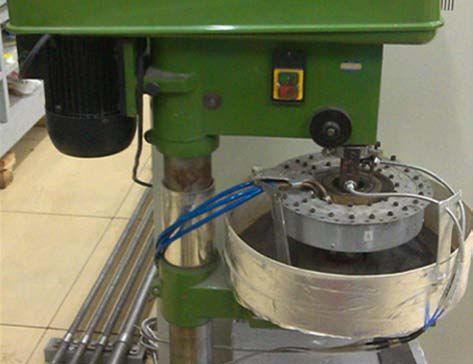
WSEAS TRANSACTIONS on SYSTEMS                                                     Pan Xin, Wu Hai-Qi, Gao Jin-Ji, Mu Yu-Zhe

produce the correction mass online. Dieter et al.                      Section 3. In order to find the optimal control path,
presented a liquid injection balancer for the first                    simulations on several paths were also done. In
time in 1976 [10]. It had a simple construction, was                   addition, we performed balancing experiments on
easy to manufacture and didn’t have movable                            two test rigs without stopping the machines in
assembly in rotating part, which made it the perfect                   Section 4.
solution for high speed application. However, such a
balancer also had several disadvantages: (1) the
liquid injection subordinate system was complex                        2 System design
and expensive, (2) the balancing capacity decreased                    The balancing device introduced in this paper is one
with increasing balancing number, (3) the balanced                     of the liquid- transfer balancing devices. The power
state could not be maintained when the machines                        source of liquid transfer in the device is compressed
stopped. In order to overcome these disadvantages,                     air, so the device is known as Liquid-transfer
many improvement works have been done [11-14].                         automatic balancing device driven by compressed
     Different with the passive balancing, the active                  air. The system block diagram of the device is
balancing requires an extra controller to form                         shown in Fig.1, and its working principle is as
commands. Many studies have been performed on                          follows: a displacement sensor and a speed sensor
the advanced control methods [15-29]. For the                          are fitted above the rotor to detect the amplitude and
active balancing controller, two major methods are                     phase of unbalance vibration; only when the
used to determine the position of initial unbalance:                   synchronous vibration amplitude is higher than the
optional control method and influence coefficient                      limiting value, the control unit starts working;
method. The former utilizes trial action of whole                      according to these two parameters, the control unit
cycle or several positions to find the final solution,                 determines the correction weight of rotor and sends
while the latter calculates the correction mass using                  control commands to the solenoid valves in valve
influence coefficient before balancing [30-32]. After                  block; compressed air is then led to the required
that, the optimization of control path is also                         chamber by the gas channels in the device, and the
important to minimize the balancing time and                           liquid in corresponding chamber is driven to its
reduce unbalance response effectively [33].                            opposite chamber; through the liquid transfer
     In this study, we proposed a new type of liquid                   between opposite chambers, the liquid distribution
active balancing device in which compressed air is                     is changed and a compensation weight is produced
used for driving the balancing liquid to transfer                      to balance the rotor. In the balancing system, an air
between opposite chambers. Due to different                            compressor is needed to work as air source. An air
requirements of installation, two specific structures                  filter and a pressure reducing valve are also needed
were described in Section 2: one can be mounted in                     to adjust the compressed air.
the middle of rotor and the other can be mounted at                          In the balancing system, balancing actuator is a
one end. The target control method utilizing                           core component which is comprised by balancing
influence coefficients was used to calculate                           disc and air distributor.
compensation weight and form control commands in

 1. Counterweight wheel 2. Connecting flange 3. Drive shaft 4. Acceleration sensor 5. Displacement sensor 6. Speed sensor 7.Control
   unit 8. Air source 9. Air filter 10. Pressure reducing valve 11. Electromagnetic valve block 12. Air distributor 13. Balancing disc
                                        Fig.1 Principle diagram of balancing system

     E-ISSN: 2224-2678                                           303                                             Volume 13, 2014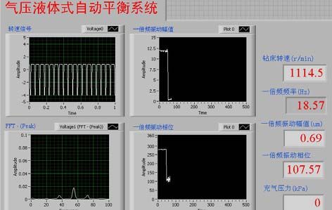
WSEAS TRANSACTIONS on SYSTEMS                                            Pan Xin, Wu Hai-Qi, Gao Jin-Ji, Mu Yu-Zhe

      The balancing disc is mounted on the rotor and            this air gap should be about dozens of microns. Two
corotates with the rotor. Shown in Fig. 2, balancing            ball bearings are required to ensure the long-term
disc includes four chambers, substantially disposed             operation of the air distributor in such a small gap.
at equal angular intervals, for containing the                  The stator cannot corotate with the balancing disc,
balancing liquid which has been infused before the              but it can move with the balancing disc in other
device starts up. At the bottom of these chambers,              directions. Owing to the soft support of the stator,
there are two liquid tubes, each connecting two                 the bearings only bear the gravity and the harmonic
opposite chambers. The two ends of each                         vibration force of the stator, which makes the
connecting tube are at the maximum radius of the                bearings have a long service life.
chambers so as to immerse in the balancing liquid
during the rotation of the rotor. In this way,
compressed air is also prevented from entering the
connecting tube. Each connecting tube extends on a
decreasing radius of curvature from one end to the
centre of the tube. This uses centrifugal force during
rotation to prevent the balancing liquid in the tube
from transferring into the chamber at the other end
of the tube, so the centre of the tube must be lower
than the liquid level of both chambers. In addition,
the balancing disc also includes four gas tubes for                             a) Mounted in the middle
supplying compressed air to the chambers. When
the compressed air is led to one chamber, the
pressure of the chamber rises gradually. When the
pressure is high enough to overcome the centrifugal
force, the balancing liquid is transferred to the
diametrically opposite chamber through the
connecting tube.

                                                                                 b) Mounted at the end
                                                                     Fig.3 Structure drawings of air distributor

                                                                      According to the different requirements of
                                                                installation site, the balancing actuator can be
                                                                divided into two specific structures: one can be
                                                                mounted in the middle of the rotor and the other can
                                                                mounted at the two ends. Their differences are
                                                                mainly in air distributor, shown in Fig.3. For the air
     Fig.2 Schematic diagram of balancing disc                  distributor mounted in the middle, its outer ring is a
                                                                stationary part used to install air pipelines and inner
     The air distributor is used to deliver air from            ring is a rotating part corotating with the rotor.
the stationary air pipelines to the rotating balancing          Compared with this structure, the structure mounted
disc and consists of a stationary part, a rotating part         at two ends is simpler: its rotating part is integrated
and two ball bearings. The stationary part is                   into the inner wall of the liquid chamber and only a
connected with air pipelines and the rotating part is           middle stator is needed.
connected with balancing disc. For the mating
surfaces of these two parts, there is at least one
surface which has annular grooves to transfer                   3 Control strategy
compressed air. The stationary and rotating parts are           In order to control the balancing actuator, a
separated by an air gap which should be as small as             target control method is proposed to calculate
possible without allowing frictional contact between            the compensation weight and form the control
them during machine operation. More particularly,

    E-ISSN: 2224-2678                                     304                                        Volume 13, 2014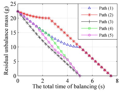
WSEAS TRANSACTIONS on SYSTEMS                                         Pan Xin, Wu Hai-Qi, Gao Jin-Ji, Mu Yu-Zhe

commands. The method has three main                          used to calculate the amount and phase of the initial
features: 1) before the balancing actuator starts            unbalance which is the balancing target, and the
working, the control unit has already                        influence coefficients representing the relationship
determined the amount and phase of the                       between vibration and unbalance are entered into
unbalance; 2) during the balancing process, the              the control unit in advance.
                                                                  3) Transition. In this part, the amount of
gas injection operation has a definite target; 3)
                                                             unbalance is converted to the total time of gas
during the balancing process, the vibration                  injection. The transition method can be Proportion
amplitude of the rotor decreases monotonically               Coefficient method or Adaptive control method.
and there is no misadjustment phenomenon.                         4) Distribution. According to the phase of
The circular flow diagram is shown in Fig.4.                 unbalance, the total time is distributed to the
            1- Begin Active balancing                        corresponding chambers. That is to say, the action
                                                             time of each solenoid valve corresponding to one
                                                             liquid chamber can be got through this part.
                                                                  5) Command formation. The action time of
         2- Data collection and extraction
                                                             these four solenoid valves in valve block are
                                                             combined in a fixed order to form the control
                                                             command, and the order will be discussed in the
                                              No             next section.
                   3-Vibration>
                    Limit value?
                                                             3.2 Data extraction
                          Yes                                When the vibration signal passes through digital
         4- Calculate the initial unbalance                  filter, part of the signal distortion and a time delay
                                                             will happen, which definitely causes error for
                                                             measuring results. In order to extract the vibration
                                                             phase accurately, Tracking Filter method is used to
           5- Calculate the total time of                    process the vibration signal in this system. The
                   gas injection                             initial vibration signal is written as follows:
                                                                                               N
                                                               x(t ) A0 cos(ω0t − ϕ0 ) + ∑ Ai cos(ωi t − ϕi ) (1)
                                                               =
          6- Calculate the action time of                                                     i =1
               each liquid chamber                           where ω0 is the working speed of the detected
                                                             machines.
                                                                 The control program provides two orthogonal
           7- Control paths optimization
                                                             sinusoidal signals y1 and y2 to multiply the
                                                             vibration signal separately. The frequency of the
                  8- Gas injection                           two signals is equal to the working speed, so they
                                                             can be written as,
                                                                   y1 (t ) = sin(ω0t )                       (2)
 Fig.4 Circular flow-diagram of balancing system
                                                                  y2 (t ) = cos(ω0t )                                  (3)
                                                                  Multiplying Eq. (1) by Eq. (2) gives,
3.1 Basic principle                                                             1           1
                                                                 x(t ) y1 (t ) = A0 sin ϕ0 + A0 sin(2ω0t − ϕ0 )
The target control method can be divided into five                              2           2
parts:                                                                               N
                                                                                  1
     1) Data collection and extraction. This part is                            + ∑ Ai sin [ (ω0 + ωi )t − ϕi ] (4)
used to receive the real-time vibration signals of                                2 i =1
detected device and extract synchronous component                                 1 N
induced by unbalance. For the extraction process,                               + ∑ Ai sin [ (ω0 + ωi )t + ϕi ]
there are several common methods, such as
                                                                                  2 i =1
Tracking filter method and FFT method.                            Similarly, multiplying Eq. (1) by Eq. (3) gives
     2) Target determination. From the synchronous
vibration signal, influence coefficient method is

    E-ISSN: 2224-2678                                  305                                           Volume 13, 2014
WSEAS TRANSACTIONS on SYSTEMS Pan Xin, Wu Hai-Qi, Gao Jin-Ji, Mu Yu-Zhe
1 1 =
T m=q U qk
x(t ) y2 (t ) = A0 cos ϕ0 + A0 cos(2ω0t − ϕ0 )
2 2 (13)
1 N For the balancing device proposed in this
+ ∑ Ai cos [ (ω0 + ωi )t − ϕi ] (5) paper, if compressed air is injected to one chamber,
2 i =1 a correction vector is formed in its opposite
1 N chamber. The phase of gas injection ψ is defined
+ ∑ Ai cos [(ω0 + ωi )t + ϕi ]
2 i =1 by,
Through a low pass filter, two DC components ψ= θ + 180
can be extracted as, (14)
According to sine or cosine theorem, the total
Vx = 1 A0 sin ϕ0 Vy = 1 A0 cos ϕ0 (6) time is resolved to these four chambers and the open
2 2
Therefore, the amplitude and phase of time of each solenoid valve is confirmed.
unbalance vibration can be given by,
V0 2 Vx2 + Vy2 ; ϕ0 = arctan(Vx / Vy )
= (7)
3.4 Control paths optimization
During the resolving process of gas injection time,
there are several cases: 1) when the phase of gas
3.3 Calculation of action time injection is at 0, 90, 180 or 270 degree, the
According to influence coefficient method, the balancing device only needs to inject gas to one
relationship between the initial unbalance vibration chamber; 2) when the phase of gas injection is at 45,
signal V0 and the unbalance vector U 0 of the 135, 225 or 315 degree, the balancing device needs
to inject gas to two neighbouring chambers
detected device before balancing can be defined as,
simultaneously, and the gas injection times of these
V0= K ⋅ U 0 (8) two chambers are also equal; 3) when the phase of
Similarly, the unbalance response after gas injection is at other positions, the balancing
balancing is given by, device needs to inject gas to two chambers, but
these two chambers have different times. For the
V1 =K ⋅ (U 0 + U1 ) (9)
case 3), we should consider the gas injection order
where U1 is the correction mass vector formed by of these two chambers and choose one control path
the balancing actuator after balancing. in which the unbalance response can be reduced
Subtracting Eq. (8) from Eq. (9) gives quickly.
{ }
In order to compare the control results of
V1 − V0 = K ⋅ (U 0 + U1 ) − U 0 different control paths, we take the gas injection
(10) phase (45 < ψ < 90) for example.
The key of balancing is to find correction mass Assuming that the initial unbalance mass is
vector that makes the response zero after balancing. m and its phase is β which is equal to gas injection
Hence, the correction vector can be
phase, we resolve the initial unbalance vector to the
U1 = U θ
− K −1 ⋅ V0 =∠ real and imaginary axis and the process can be
(11) written as,
→
where U and β are the amplitude and phase of M = m∠β = m cos β + i ⋅ ( m sin β ) (15)
correction mass vector, respectively.
where β = ψ , and 45 < β < 90 .
If the balancing ability formed by a unit mass
of balancing liquid is represented as k , the mass of In this case, compressed air is delivered to
balancing liquid transferred by compressed air can Chamber A and B. The mass flows q in these two
be represented as, connecting tubes are equal, and the gas injection
→ time of Chamber A and B can be written as,
M = m∠θ = (U k ) ∠θ ta = m cos β q , tb = m sin β q (16)
(12) where tb > ta > 0 , which means that the time of
During the transfer process, the mass flow rate
q in the connecting tube of two opposite chambers Chamber B is longer than that of chamber A.
In this case, there are five control paths for
can be considered as a constant. Therefore, the total
different gas injection order:
time of gas injection T can be written as,
E-ISSN: 2224-2678 306 Volume 13, 2014WSEAS TRANSACTIONS on SYSTEMS Pan Xin, Wu Hai-Qi, Gao Jin-Ji, Mu Yu-Zhe
(1) Open the solenoid valve of chamber B During the balancing process, the residual
firstly, and the solenoid valve of chamber A does unbalance can be represented as,
not begin to work till the gas injection of chamber B (m cos β − 2tq) + i ⋅ (m sin β − 2tq) (0 ≤ t ≤ ta )
is finished. So the balancing process is divided into mrest =
(m cos β − 2ta q) + i ⋅ (m sin β − 2tq) (ta < t ≤ tb )
two parts, and the residual unbalance can be
represented as, (19)
(4) Open the solenoid valve of chamber B
(m cos β ) + i ⋅ (m sin β − 2tq ) (0 ≤ t ≤ tb )
mrest = firstly. After a little while, the solenoid valve of
(m cos β − 2(t − tb )q ) + i ⋅ (m sin β − 2tb q ) (tb < t ≤ ta + tb )
chamber A is also open, and these two solenoid
(17) valves are closed at the same time. During the
(2) Open the solenoid valve of chamber A balancing process, the residual unbalance can be
firstly, and the solenoid valve of chamber B does represented as,
not begin to work till the gas injection of chamber A (m cos β ) + i ⋅ (m sin β − 2tq) (0 ≤ t ≤ tb − ta )
is finished. The balancing process is also divided mrest =
(m cos β − 2(t − (tb − ta ))q) + i ⋅ (m sin β − 2tq) (tb − ta < t ≤ tb )
into two parts, and the residual unbalance can be
(20)
represented as,
(5) The gas injection time of chamber A is
(m cos β − 2tq) + i ⋅ (m sin β ) (0 ≤ t ≤ ta )
mrest = divided into several parts. During the gas injection
(m cos β − 2ta q) + i ⋅ (m sin β − 2(t − ta )q) (ta < t ≤ ta + tb ) process of chamber B, open the solenoid valve of
(18) chamber A discontinuously. If the time of chamber
(3) Open the solenoid valves of chamber A and A is divided into j parts, the balancing process is
B at the same time. When the gas injection of divided into 2j parts and the residual unbalance can
chamber A is finished, its corresponding solenoid be represented as,
valve is closed, but the solenoid valve of chamber B
is still open until its gas injection is also finished.
(m cos β ) + i ⋅ (m sin β − 2tq ) (0 ≤ t ≤ (ta − tb ) / j )
(m cos β − 2(t − (t − t ) / j )q) + i ⋅ (m sin β − 2tq) ((ta − tb ) / j < t ≤ ta / j )
a b
(m cos β − 2tb q / j ) + i ⋅ (m sin β − 2tq) (ta / j < t ≤ (2ta − tb ) / j )
(21)
mrest = (m cos β − 2(t − 2(ta − tb ) / j )q) + i ⋅ (m sin β − 2tq) ((2ta − tb ) / j < t ≤ 2ta / j )
(m cos β − 2( j − 1)tb q / j ) + i ⋅ (m sin β − 2tq ) (( j − 1)ta / j < t ≤ ( jta − tb ) / j )
(m cos β − 2(t − j (ta − tb ) / j )q ) + i ⋅ (m sin β − 2tq ) (( jta − tb ) / j < t ≤ ta ) 2 j×1
For example, m cos β = 10 ( g ) , Comparing these five control curves, the control
speed and control effect of Path (3) are better than
m sin β = 20 ( g ) , q = 2 ( g / s ) . In this situation, the others. So when the control unit forms the
ta = 2.5 ( s) , tb = 5 ( s ) . Utilizing Eq. (17) – (21), the control command, it should follow Path (3) and the
command formation is comprised by three steps: 1)
change curve of residual unbalance for different open the solenoid valves of two targeting chambers
control paths can be calculated, and the results are simultaneously, 2) close the solenoid valve of one
shown in Fig. 5. chamber, the time of which is shorter than the other,
3) close the other solenoid valve and the gas
injection process is finished.
4 Balancing experiment
4.1 Balancing device mounted in the middle
The bench drilling machine is remodeled to build a
vertical-type experimental setup, shown in Fig. 6. Its
drill bit is the detected rotor, in the middle of which
the active balancing device is mounted. Two eddy
current sensors are used to measure the unbalance
Fig.5 Comparison of control paths vibration of the drill bit.
E-ISSN: 2224-2678 307 Volume 13, 2014WSEAS TRANSACTIONS on SYSTEMS Pan Xin, Wu Hai-Qi, Gao Jin-Ji, Mu Yu-Zhe
The balancing disc and the inner ring of the air Fig.7 Data processing program using Labview
distributor are fixed to the rotor through a
connecting flange which is welded to the drill bit. Limited by the running speed of bench drilling
The outer ring of the air distributor stays still during machine, a balancing experiment is performed at
operation and has four gas-type fittings, connected 1080 rpm, and the balancing result is shown in Fig.
with four gas pipelines, to deliver compressed air to 8. After the rotor ran stably at the working speed,
the inner ring and the balancing disc. The outer ring the amplitude of initial unbalance response was
is fixed to the machine foundation through a soft about 26.1 um peak-to-peak and the phase is 203
method, that is to say, this method only limits its degree. The active balancing system was then
rotation, but does not limit its movements in other started and the total gas injection time was about 5
directions. This fixed mode reduces the operating seconds. The response decreased to 1.0 um peak-to-
load of bearings between the outer and inner rings peak after balancing and the amount of vibration
greatly, which is good for a long service life. decreased by 96.2%. Restricted by the accuracy of
the drilling machine, when the vibration amplitude
was lower than 1.0 um, the phase of vibration
fluctuated up and down between 220 degree and 150
degree, which affected the improvement of
Rotor Speed sensor
balancing accuracy. Even so, the results has already
proved the availability of the proposed active
balancing device.
Driving motor
Air pipelines
Balancing disc Air distributor
Fig.6 Experimental device of balancing system
installed in the middle of rotor
The NI DAQ card PCI6220 and Digital I/O
card PCI 6515 are adopted as the hardware module.
In order to control the active balancing device
automatically, we develop a data processing and
active control program using the Labview software, Fig.8 Balancing result of balancing system installed
shown in Fig.7. While the detected machine is in the middle of rotor
running, the program always monitors the vibration
status of the drill bit. Once the synchronous
vibration amplitude is higher than the limiting value, 4.2 Balancing device mounted at the end
the program sends out control command and the The spindle system for cylindrical grinding
balancing actuator starts working. The compressed machine, capable of mounting the active balancing
air used during active balancing is supplied by an device we proposed in this paper, is shown in Fig.9.
oilless air compressor, and its air outlet pressure is Single plane balancing that uses one balancing
set to 0.1 MPa. device was performed, by aiming at the end of the
spindle.
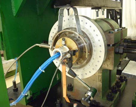
The counterweight wheel, which has the same
geometrical dimensions as the standard grinding
wheel and is installed to the spindle by two wheel
flanges, is the vibration source of active balancing
experiment. The balancing disc of balancing
actuator is integrated into one wheel flange, which
is quite near the vibration source and good for active
balancing. The structure of the air distributor is
simplified, which only need one still stator in the
centre hole of the balancing disc. In the stator, there
E-ISSN: 2224-2678 308 Volume 13, 2014WSEAS TRANSACTIONS on SYSTEMS Pan Xin, Wu Hai-Qi, Gao Jin-Ji, Mu Yu-Zhe
are four axial gas channels which are connected to peak-to-peak and the phase was 200 degree. The
four air pipelines and used to deliver compressed air active balancing system was then started and the
to the balancing disc. Two ball bearings are required total gas injection time was about 15 seconds. The
to ensure the running clearance between the stator response decreased to 0.3 um peak-to-peak after
and balancing disc. The stator cannot corotate with balancing and the amount of vibration decreased by
the balancing disc, but it can move with the 96.5%. Due to the small value of vibration
balancing disc in other directions. Owing to the soft amplitude, the phase of vibration was no longer a
support of the stator, the bearings only bear the fixed value, but fluctuated between 150 degree and
gravity and the harmonic vibration force of the 170 degree.
stator, which are about dozens of N. Compared with
the limit load of these bearings, which is more than
2000 N, the operating load is quite small. The air 5 Conclusion
source, the valve block and the control unit are the In this paper, we propose a liquid active
same with the devices used in the vertical-type balancing device which can be mounted both in
experimental setup, but the air outlet pressure is set
the middle and at one end of the rotor. We
to 0.3 MPa.
provided a target control method in which the
gas injection target has already confirmed
Spindle
Displacement sensor before balancing and the unbalance response of
rotor decreases monotonically during balancing
process.
Wheel Different control paths would generate
different balancing effects, so simulations on
Air pipelines several control paths were done to find the
Balancing disc optimal solution. The chosen control path is as
follows: when compressed air needs to be
Speed sensor
injected into two chambers, the solenoid valves
of the two target chambers should be open at
the same time; when the gas injection of one
Fig.9 Experimental device of balancing system chamber is finished, its corresponding solenoid
installed at the end of rotor valve is closed, but the solenoid valve of the
other chamber is still open until its gas injection
is also finished.
Based on the target control method, active
balancing works were also carried out on two
experimental setups. The results showed that
both of the two active balancing devices could
reduce the unbalance response by more than
90% within 15 s, which verified the feasibility
and availability of the balancing devices.
Acknowledgements
This study was supported by the Major State
Basic Research Development Program of China
(973 Program No. 2012CB026000) and Natural
Fig.10 Balancing result of balancing system
Science Foundation of China in Key Projects ( No.
installed at the end of rotor
51135001). The authors would like to thank for
supporting this work.
The balancing experiment is performed at 5000
rpm, and the balancing result is shown in Fig. 10.
After the rotor ran stably at the balancing speed, the
References:
amplitude of initial unbalance response was 8.6 um
E-ISSN: 2224-2678 309 Volume 13, 2014WSEAS TRANSACTIONS on SYSTEMS Pan Xin, Wu Hai-Qi, Gao Jin-Ji, Mu Yu-Zhe
[1] D.J. Rodrigues, A.R. Champneys, M.I. Friswell, [12] S.Z. He. Study of liquid release auto-balancing
R.E. Wilson, Experimental investigation of a head. Journal of Zhejiang University
single-plane automatic balancing mechanism (Engineering Science), Vol. 35, No. 4, 2001,
for a rigid rotor, Journal of Sound and pp. 418-422.
Vibration, Vol. 330, No.3, 2011, pp.385-403. [13] Y. Li, W. M. Wang, L.Q. Huang, et al. A rotor
[2] H.W. Chen, Q.J. Zhang and S.Y. Fan, Study on auto-balance device with continuously
steady-state response of a vertical axis injecting and draining liquid based on
automatic washing machine with a hydraulic peristaltic pumps. Journal of Vibration and
balancer using a new approach and a method Shock, Vol. 30, No. 4, 2011, pp.38-41.
for getting a smaller deflection angle, Journal [14] Y. Zhang, X.S. Mei, Z.B. Hu, et al. Design and
of Sound and Vibration, Vol. 330, No.9, 2011, performance analysis of hydrojet-typed
pp. 2017–2030. balancing device for high-speed machine tool
[3] R. Horvath, G.T. Flowers, J. Fausz, Passive spindle. Journal of Xi’an Jiaotong University,
Balancing of Rotor Systems Using Pendulum Vol. 47, No. 3, 2013, pp.y1-y6.
Balancers, Journal of Vibration and Acoustics, [15] A. V. Doroshin, F. Neri. Open research issues
Vol. 130, No.4, 2008, pp.041011. on Nonlinear Dynamics, Dynamical Systems
[4] R.G. Thomas, F.L. Alan. Precision tracking of a and Processes. Wseas Transactions on Systems,
rotating shaft with magnetic bearings by Vol. 13, 2014, in press.
nonlinear decoupled disturbance observers. [16] C.Ciufudean, F. Neri. Open research issues on
IEEE Transactions on Control systems Multi-Models for Complex Technological
technology, Vol. 15, No.6, 2007, pp.1112- Systems. Wseas Transactions on Systems, Vol.
1121. 13, 2014, in press.
[5] K.J. Jiang, C.S. Zhu and M. Tang, A Uniform [17] F. Neri. Open research issues on Computational
Control Method for Imbalance Compensation Techniques for Financial Applications. Wseas
and Automation Balancing in Active Magnetic Transactions on Systems, Vol. 13, 2014, in
Bearing-Rotor Systems, Journal of Dynamic press.
Systems,Measurement, and Control, Vol. 134, [18] P.Karthikeyan, F. Neri. Open research issues
No.2, 2012, pp. 021006. on Deregulated Electricity Market:
[6] V.J. Vande, Continuous automatic balancing of Investigation and Solution Methodologies.
rotating systems, Journal of Mechanical Wseas Transactions on Systems, Vol. 13, 2014,
Engineering Science, Vol. 6, No.3, 1964, pp. in press.
264-269. [19] M.Panoiu, F. Neri. Open research issues on
[7] S.W. Dyer and J. Ni, Adaptive influence Modeling, Simulation and Optimization in
coefficient control of single-plane active Electrical Systems. Wseas Transactions on
balancing systems for rotating machinery, Systems, Vol. 13, 2014, in press.
Journal of Manufacturing Science and [20] F. Neri. Open research issues on Advanced
Engineering, Vol. 123, No.5, 2001, pp.291- Control Methods: Theory and Application.
298. Wseas Transactions on Systems, Vol. 13, 2014,
[8] W. Shen, L.D. He, J.J. Gao, et al. Dealing with in press.
vibration problems of a fume turbine’s rotor by [21] P. Hájek, F. Neri. An introduction to the special
using an electromagnetic active balancing issue on computational techniques for trading
device. Journal of Power Engineering, Vol. 26, systems, time series forecasting, stock market
No. 3, 2006, pp.337-341. modeling, financial assets modelling. Wseas
[9] Y.R. Su, L.D. He, Z.W. Wang, et al. Study on Transactions on Business and Economics, Vol.
dual-plane active hydraulic balancing 10, No. 4, 2013, pp. 201-292.
technology for single-disk rigid rotor system. [22] M. Azzouzi, F. Neri. An introduction to the
Proceedings of the CSEE, Vol. 29, No. 35, special issue on advanced control of energy
2009, pp. 119-124. systems. Wseas Transactions on Power
[10] D. Birkenstack and O. Jager, Multi-chambered Systems, Vol. 8, No. 3, 2013, pp. 103.
fluid balancing apparatus, U.S. Patent, US395 [23] Z. Bojkovic, F. Neri, An introduction to the
0897, 1976. special issue on advances on interactive
[11] C.C. James, T.L. Richard, A.M. Frank, et al. multimedia systems. Wseas Transactions on
Liquid-chamber apparatus for active, dynamic Systems, Vol. 12, No. 7, 2013, pp. 337-338.
balancing of rotating machinery. U.S.Patent, [24] L. Pekař, F. Neri. An introduction to the special
US 5490436, 1996. issue on advanced control methods: Theory and
E-ISSN: 2224-2678 310 Volume 13, 2014WSEAS TRANSACTIONS on SYSTEMS Pan Xin, Wu Hai-Qi, Gao Jin-Ji, Mu Yu-Zhe
application. Wseas Transactions on Systems, systems: Applications, methodology,
Vol. 12, No. 6, 2013, pp. 301-303. technology. Wseas Transactions on Systems,
[25] C. Guarnaccia, F. Neri. An introduction to the Vol. 11, No. 9, 2012, pp. 477-478.
special issue on recent methods on physical [30] L.Q. Huang, W.M. Wang, Y.R. Su, et al.
polluting agents and environment modeling Optimal control method and test for rigid rotor
and simulation. Wseas Transactions on auto-balancing, Journal of Vibration and
Systems, Vol. 12, No. 2, 2013, pp. 53-54. Shock, Vol. 30, No. 5, 2011, pp.101-105.
[26] F. Neri. An introduction to the special issue on [31] S.W. Dyer, J. Ni, J.J. Shi, et al., Robust
computational techniques for trading systems, optimal influence-coefficient control of
time series forecasting, stock market modeling, multiple-plane active rotor balancing systems,
and financial assets modelling. Wseas Journal of Dynamic Systems, Measurement,
Transactions on Systems, Vol. 11, No. 12, 2012, and Control, Vol. 124, No. 3, 2002, pp.41-46.
pp. 659-660. [32] J.D. Moon, B.S. Kim, and S.H. Lee,
[27] M. Muntean, F. Neri. Foreword to the special Development of the active balancing device for
issue on collaborative systems. Wseas high-speed spindle system using influence
Transactions on Systems, Vol. 11, No. 11, 2012, coefficients, International Journal of Machine
pp. 617. Tools & Manufacture , Vol. 46, No. 9, 2006,
[28] L. Pekař, F. Neri. An introduction to the special pp.978-987.
issue on time delay systems: Modelling, [33] L.F. Chen, X. Cao, J.J. Gao. A study on
identification, stability, control andapplications. electromagnetic driven bi-disc compensator for
WSEAS Transactions on Systems, Vol. 11, No. rotor auto-balancing and its movement control.
10, 2012, pp. 539-540. Wseas transactions on systems and control,
[29] C. Volos, F. Neri. An introduction to the Vol. 5, No. 5, 2010, pp.333-342.
special issue: Recent advances in defense
E-ISSN: 2224-2678 311 Volume 13, 2014You can also read