A Breath of Fresh Air in Electro-Hydraulic Cooling Control - HYDAC
←
→
Page content transcription
If your browser does not render page correctly, please read the page content below
A Breath of Fresh Air
               in Electro-Hydraulic
               Cooling Control

Designed for
EU Stage V
 Emission
 Directive

                                       EN 5.315.2 / 09.18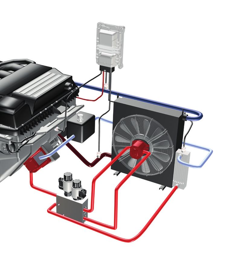
Your partner for expertise
in electro-hydraulic
needs-based cooling control
Optimal HYDAC components are designed for TIER 5 and EU stage V emission directive
As a result of the increased requirements concerning energy efficiency and noise development
operating in mobile machines, cooling systems for these vehicles have to be designed to the limits of
physical possibility. Special design features lay the foundation for optimal cooling systems.
temperatures
for low fuel NOX PM [g/kWh]
consumption
Applicable to all Applicable to all
work machinery and units work machinery,
EU-Stage I with diesel engines machines, units and
and a clean
9.2 | 0.54 for the NRMM sector combustions engines
10.0 0.50 from 19 kW up to < 560 kW which are used
in the NRMM sector
environment 8.0
6.0
0.40
0.30
EU-Stage II
6.0 | 0.20
EU-Stage IIIA
from 0 kW up to > 560 kW
4.0 | 0.20
4.0 0.20
EU-Stage IIIB
Selecting the right cooler and the 2.0 | 0.025 EU-Stage IV EU-Stage V
2.0 0.10
relevant fan control is one of the 0.4 | 0.025 0.4 | 0.015
0
most important stages in machine 1998 1999 2000 2001 2002 2003 2004 2005 2006 2007 2008 2009 2010 2011 2012 2013 2014 2015 2016 2017 2018 2019 2020 2021 2022
0
development.
0.4 | 0.01
Approximately 5 - 10% of the 2.0 0.10
2.0 | 0.02 EURO VI
nominal power of the drive motor is 4.0 0.20 3.5 | 0.02
EURO V
allotted to the fan drive alone. 6.0 0.30 5.0 | 0.10
EURO IV
EURO III
8.0 0.40
Generally speaking, fan drives are
divided into three different drive 10.0 0.50
concepts: NOX PM [g/kWh]
1 Direct fan drive
2 Electric fan drive
3 Hydrostatic fan drive
Our technology Your advantages
HYDAC offers electric and hydro- Flexibility
static fan drives. The choice of fan
lF
an controls in various nominal sizes l Specifically adapted
drive is based primarily on the
with / without reversing function to customer requirements
machine design, the cooling
requirement and of course the Safety
installation space available. lF
ail-safe mode in event of power failure l Maximum protection for motor / cooler
lO
ptional reversal of direction of rotation l Cooler cleaning
Hydraulic components already
installed in the machine simplify the (reversing function)
choice of fan drive (see matrix on lS
oft start and speed control l Prevents pressure peaks
page 3). in the hydraulic system
Energy efficiency and life cycle cost
In the current combustion engine
generation, the legally required lF
an control with optimized consumption l Reduction in fuel requirement
reduction in emissions is achieved by (10 % reduction in speed reduces
optimal combustion temperatures, the energy requirement by approx. 27 %)
amongst other things. lF
an speed can be controlled l Precise temperature regulation according
The appropriate needs-based cooling proportionally to cooling requirement and increased
capacity is provided by controlled fan service life of the machine
drives built onto the cooling module. lC
onstructive characteristics l Low hydraulic energy losses
in design process
Other advantages are a reduction in
noise level and fuel consumption. lN
eeds-based cooling l Energy saving
lQ
uickly reaches operating temperature l Reduced friction protects the material
Noise reduction
l3
dB(A) reduction in noise can be l Lower noise level (lower statutory noise
achieved by just 13 % reduction emission value – 70 % of nominal)
Note
in speed for continuously controlled fans than for
EN 5.315.2 / 09.18
The information in this brochure relates
to the operating conditions and applications fans operated in ON/OFF mode
described. For applications and operating
conditions not described, please contact
Comfort
the relevant technical department. lV
ibration resistant design l No vibrations in the machine
Subject to technical modifications.
2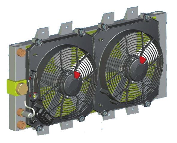
System diagram
                     Cooler / fan

                     Matrix for system selection

                                                      Ambient conditions (simplified)
                         Fan power                 Clean                     Contaminated

                       > approx. 25 kW
                                         Variable displacement pump    Variable displacement pump
                                          without reversing function     with reversing function

                       < approx. 25 kW
                                         Fixed displacement pump        Fixed displacement pump
                                              with fan control               with fan control
                                         without reversing function      with reversing function

                                                                              Electric drive
                       < approx. 18 kW          Electric drive                with electrical
                                                                            reversing function
EN 5.315.2 / 09.18

  3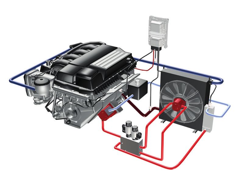
Electro-hydraulic control
                     for needs-based cooling

                     As a single-source supplier of products for
                     hydraulic systems, HYDAC also offers controls
                     for needs-based cooling in mobile machines.
                     Starting with coolers, gear motors, pumps,
                     hydraulic fan controls and sensors, through
                     to electronic controls, HYDAC provides all
                     components both individually and as complete
                     systems.

                     Hydraulic fan controls
                     Hydraulic fan controls from HYDAC
                     are at the hydraulic heart of the system.
                     They control the speed of the fan depending
                     on the temperature of the medium.
                     They are supplied by a variable or fixed
                     displacement pump and can be installed
                     directly on the fan motor, on the cooler or
                     other location. As an option, these controls
                     can also be supplied with a reversing
                     function, to “purge” the cooler of external
                     dirt (e. g. dust, sand...)
                     Right from the design stage, these fan
                     controls in mobile machines are always
                     designed to be fuel efficient thus helping
                     to reduce emissions and also to meet
                     future environmental regulations efficiently
                     (e. g. Stage 5 Emission directive 2019).

                     Reversing manifold and variable
                     displacement pump
                     In the case of a variable displacement
                     pump which is controlled directly by             Gear pump fixed
                     sensors according to need, the fan control       displacement PGE
                     is no longer required and a reversing manifold   Constant supply
                     is used instead to reverse the direction         of hydraulic energy
                     of rotation of the fan motor.                    to the fan control
                     The technological basis for these controls       system.
                     is the reliable valve technology from HYDAC.
                     Systematic R&D work and completely
                     new valves provide a high degree of security
                     against system failure and long service life.
                     These valves have been specifically
                     developed for this type of control and
                     are protective against cavitation erosion.
                     This valve technology can either be              Axial piston pump
                     installed directly in external gear motors or    variable displacement
                     connected in the separate manifold.              PPV
                     This produces a compact unit for customized
                                                                      Variable supply
                     solutions.
                                                                      of hydraulic energy to
                                                                      the fan control system.
EN 5.315.2 / 09.18

  4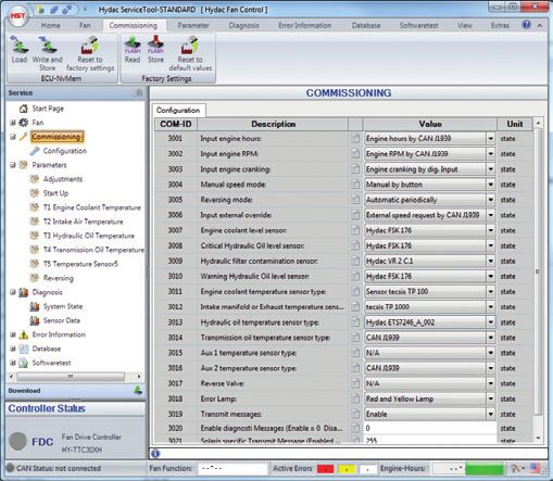
Mobile Controller                        Electronic temperature
          HY-TTC 30                                transmitters ETS 7200
                                                   and HTT 8000,
          Electronic control of the
                                                   pressure transmitters
          whole system:
                                                   HDA 8000,
          Integration of the sensors,
                                                   electro-mechanical
          control of the proportional
                                                   flow switches
          valves in the fan manifold
                                                   HFS 2000 and
          and possibly the variable
                                                   speed sensors HSS
          displacement pump.
                                                   Comprehensive range
                                                   of sensors covering all
                                                   aspects of hydraulics
                                                   for direct evaluation in
                                                   the electronic control.

                                                                  Mobile cooler
Hydraulic                                                         OK-ELH
Fan Control
B-BM                                                              Maximum cooling
                                                                  capacity is ensured
Proportional control                          Gear motor
                                                                  by the combination
of the speed of the fan                       MGE
                                                                  of high performance
motor.                                        Constant            cooling elements
Available with reversing                      supply              and hydraulic drive
option to reverse the                         of hydraulic        motors for long-term
direction of rotation.                        energy to           and trouble-free
                                              the fan.            operation.

                                        Hydraulic
                                        reversing
                                        of fan motor
                                        B-BM Rev.
                                                                                    EN 5.315.2 / 09.18

                                                                                      5
Electrical control for needs-ba
                     Electric drive fans are used primarily
                     for cooling capacities of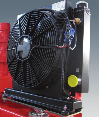
ased cooling
                                                                                  Mobile Controller HY-TTC 30
                                                                                  Electronic control of the whole system:
                                                                                  Integration of the sensors, control of the
                                                                                  proportional valves in the fan control manifold
                                                                                  and possibly the variable displacement pump.

                                                                                            Electronic temperature transmitters
                                                                                            ETS 7200 and HTT 8000,
                                                                                            pressure transmitters HDA 8000,
                                                                                            electro-mechanical flow switches
                                                                                            HFS 2000 and speed sensors HSS
                                                                                            Comprehensive range of sensors
                                                                                            covering all aspects of the hydraulics
    Oil/air cooler                                                                          for direct evaluation in the electronic
    with DC motor                                                                           control.

                                              Double fan DC
                                              with 2 integrated fuses

                                IBT

                                              1 NTC for 2 fans           1 ESC for 2 fans

                  200

 Max Speed
                  100

                   80
    Speed set %

                   60

                   40

  Min Speed
                   20

                    0
                        0   1   2     3   4    5     6   7      8   9   10   11   12   13
                                                   Analogue V
                                                                                                                                      EN 5.315.2 / 09.18

                                                                                                                                        7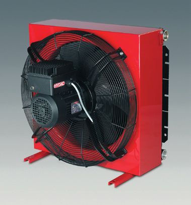
At a glance – all the HYDAC compon
                     Mobile coolers for charge air, water, hydraulic oil, gear oil
                     OK-ELH / AC-LNH or CMS
                                                        Oil/air coolers –
                                                        with hydraulic drive motor
                                                        These coolers have been specially
                                                        developed for mobile applications and
                                                        as such must guarantee high capacities
                                                        and efficiency. In addition, the coolers
                                                        must be highly compact and simple
                                                        to install in the limited space available.
                                                        Typical applications are:
                                                        l Construction machinery
                                                        l Agricultural machinery
                                                        l Forestry machinery
                                                        l Cranes

                                                        These coolers use a combination
                                                        of high-capacity cooling elements and
                                                        hydraulic drive motors to ensure long
                                                        and trouble-free operation of the
                                                        hydraulic system in the mobile sector.

                                                        Technical data:
                                                        l Cooling capacity range: 2 – 140 kW
                                                        l Hydraulic motors from 6.3 to 22 cm³/rev
                                                        l Speed of up to 2,500 rpm
                                                        l Easy disassembly of components

                                                        See brochure 5.805 (Oil/air coolers)

                     Hydraulic fan controls B-BM
                                                        Manifolds for the electro-
                                                        proportional control of the fan motor –
                                                        with or without reversing function
                                                        With integrated, inversely proportional
                                                        pressure relief valve PDB10PZ for
                                                        continuous control of the fan speed
                                                        according to the temperature.*
                                                        4/2 Directional Control Valve WK10Y to
                                                        reverse the direction of fan rotation. Anti-
                                                        cavitation valve to protect against cavitation.
                                                        Technical data:
                                                        l Operating pressure: max. 210 bar
                                                        l Flow rate: max. 40 / 60 / 70 l/min
                                                        l Supply: 12 / 24 V
EN 5.315.2 / 09.18

                                                        See brochure no. 10.148
                                                        (Hydraulic fan controls)
                                                        * In the event of system failure, maximum speed
                                                           to protect the motor
  8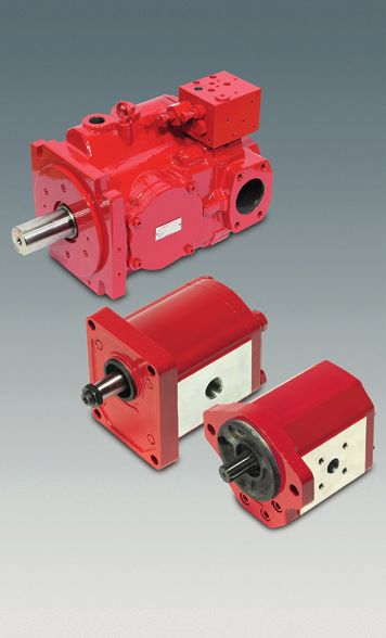
nents to control needs-based cooling
  Mobile Controller
  HY-TTC 30
                                    HYDAC provides a 16-bit mobile
                                    controller to control the hydraulic functions,
                                    namely the proportional valves integrated
                                    in the manifold, the sensors and
                                    possibly the variable pump.
                                    It is an intelligent controller with
                                    2 – 6 PWM high side outputs with current
                                    control (to control the proportional
                                    solenoids); 2 HS digital outputs
                                    (to control the switching solenoids).
                                    The controller is protected by a very
                                    robust aluminium compact enclosure.

                                    See brochure no. 18.500 (HY-TTC 30)

  Sensors
                                    Electronic temperature transmitters
                                    ETS 7200 and HTT 8000,
                                    pressure transmitters HDA 8000,
                                    electro-mechanical flow switches
                                    HFS 2000 and speed sensors HSS

                                    To monitor relevant operational data
                                    from the “needs-based cooling” control
                                    system, HYDAC has various electronic
                                    switches and transmitters to offer.

  Gear pump (fixed) or axial piston pump (variable)
  PGE / PPV / Gear motor MGE
                                    Axial piston pumps – PPV series
                                    lN
                                      ominal pressure / Max. pressure:
                                     320 / 350 bar
                                    lS
                                      pecific displacement: 16 – 200 cm3/rev
                                    lC
                                      omprehensive range of
                                     controllers available
                                    lT
                                      hrough-drive capability
                                     for multiple pump combinations.
                                    lA
                                      lso suitable for use with fire-resistant
                                     fluids (depending on specification)
                                    External gear pump – PGE series
                                    lN ominal pressure / Max. pressure:
                                      250/300 bar (size-dependent)
                                    lS pecific displacement: 0.25 – 60 cm3/rev
                                    lC ompatible with multiple pump
                                      combinations up to 25 kW
                                    External gear motor MGE
                                    lN ominal pressure / Max. pressure:
                                      200 / 220 bar
                                                                                                          Overview

                                    lS pecific displacement: 1.6 – 60 cm3/rev
                                                                                     EN 5.315.2 / 09.18

                                    See brochure no. 2.902
                                    (MGE, PGE or PPV100S)

                                                                                       9
Mobile coolers for charge air, wate
                     Air cooler with speed control AC-LN MI
                                                       The AC-LN MI air cooler series can be
                                                       used in all sectors where either oil or water-
                                                       glycol is to be cooled with air.
                                                       The integrated frequency inverter controls
                                                       the fan speed according to the temperature
                                                       of the medium in the cooling element.
                                                       Consistent outlet temperature of the
                                                       medium is achieved with lower energy
                                                       consumption and lower noise levels.

                                                       Technical data:
                                                       l Cooling capacity range: 20 – 40 kW
                                                       lC
                                                         onstant fluid temperature
                                                       l Energy efficient
                                                       lL
                                                         ower noise level

                                                       See brochure no. 5.814 (AC-LN MI)

                     Air cooler with DC motor OK-ELD
                                                       The OK-ELD series with DC motor has
                                                       been specially developed for mobile
                                                       hydraulic applications where the requirement
                                                       is for high capacity, as well as for a highly
                                                       compact design which is simple to install.
                                                       With the electronic speed control ESC it is
                                                       possible to control the fan speed smoothly,
                                                       according to the oil temperature. This ensures
                                                       that the fan speed is precisely coordinated
                                                       to the required cooling capacity and the oil
                                                       temperature remains constant.

                                                       Technical data:
                                                       l Cooling capacity up to 34 kW
                                                       l DC motor with 12 V or 24 V
                                                       l Constant oil temperature

                                                       See brochure no. 5.805 (OK-ELD)
EN 5.315.2 / 09.18

10
er, hydraulic oil, gear oil, fuel ...
Oil/air cooler with hydraulic motor OK-ELH
The use of high-capacity cooling elements
and hydraulic drive motors in the OK-ELH /
AC-LNH series ensures long and trouble-free
operation of the hydraulic system in
the mobile sector.
Typical applications for these coolers
with hydraulic motor are primarily mobile
cranes, concrete mixers and concrete
pump trucks, pavers,in the transmission
cooling ...
Technical data:
l Cooling capacity range: 2 – 140 kW
l Hydraulic motors from 6.3 to 22 cm³/rev
l Speed of up to 2,500 rpm
See brochure no. 5.808 (OK-ELH)
Combined cooler series CMS
Component combinations, for example:
l Air/air coolers
l Oil/air coolers
l Water-glycol/air coolers
The implementation of the emissions
standard requires progressive reduction
of pollutant emissions from mobile machines.
This has resulted in a sometimes drastic
increase in the amount of heat to be
dissipated and the appropriate adjustment
of the cooler size. The limited space available
in a mobile machine must therefore be utilized
efficiently and intelligently.
The following cooling circuits can be
combined together in various ways in a
CMS mobile cooler:
l Charge air cooling (CAC)
for diesel turbo engines
l Coolant cooling (RAD)
l Oil circuits
- Transmission
- Hydraulics
- Fan drive
l Fuel cooling
If required, a condenser for the air
conditioning unit can also be integrated
into the cooling system. With the aid of
our cooling calculation software (KULI),
and on the basis of available data, it is
simple to adjust for pressure losses and
heating of the cooling air which will also
Coolers
EN 5.315.2 / 09.18
occur as a result of installing a condenser.
See brochure no. 5.812 (CMS)
11Compact Hydraulics – Components
Application example Cartridge valves
l Check / anti-cavitation valves
1
l Directional control valves
l Manually adjustable pressure relief valves
2
l Inversely proportional pressure relief valves
l Bypass valves
See Catalogue 53.000 (Compact Hydraulics)
Proportional Directional control
pressure relief valve valve
2
Check / anti-cavitation valves RV
3 (Series RV08-10A-51, RV10-16A-01,
3 1
RVM06020/10120-51)
HYDAC check valves, cone poppet type,
1
2
are leak-free, prevent pressure shocks and are
designed for long service life. They supply the
A B proportional valves and ensure cavitation-free
2 4 suction in this system.
l Durable and robust
lP max = 350 bar; Q max = 80 l/min
3 1 See brochure nos. 5.912, 5.953, 5.952, 5.951
Directional control valves WK10Y / WK12X / WK06C
4/2 solenoid directional valves
2 WK10Y-40 / WK121X-40 specially designed
2 4
for reversing the direction of rotation of the fan
l In main flow direction, lower pressure losses than
3 1
NG6 spool valve
3 1
lM
ore compact solution than Cetop spool valve
l Performance adapted to the application
lR
obust spool design for extreme environmental
2 4 conditions in the engine compartment: heat,
dust, water
l Deutsch plug with IP6K9K protection
3 1 See brochure nos. 5.971.1, 5.961.1
3/2 mini solenoid directional valves WK06C-01
lR
eduction in installation spaces and weight
2 lE
xcellent performance for safe switching
2 4 See brochure no. 5.149.0
3 1 4/3 directional spool valve manifold specially
designed for reversing the rotation direction
3 1
of the fan
l Hydraulically controlled
l Very low pressure loss
2 4
l Patent-pending manifold
l Gentle switching
l Requires only a small pilot valve (WK06)
3 1
l P max = 350 bar; Q max = 120 l/min
Proportional pressure relief valve PDB08PZ-30 to PDB16PZ-30
2 4 HYDAC offers a full range of proportional
pressure relief valves from size 08 to size 16.
2
They have a common design feature which
EN 5.315.2 / 09.18
3 1 is significant in protecting against cavitation.
1
This phenomenon occurs more frequently with
fan controls in particular, due to the high speed
of the fan, causing the housing to fail very quickly.
12for fan controls
In each case the valve is connected in the bypass to
250 the hydraulic motor and restricts the pressure to the
motor. The speed of the fan motor is no longer depen-
200 dent on the speed of the diesel engine. The cooling
Pressure P [bar]
requirement is controlled by temperature sensors.
150
l Optimal operating temperature of the
100 combustion engine achieved by electronic con-
trol of the hydrostatic fan drive
50
l Complies with emission directive
(TIER 5, Stage V)
0
0 50 100 150 200 250 300 350 400 450 500 l Fail-safe design: inverse control in the case
Current intensity l [mA] of electrical failure – maximum fan speed
to protect against overheating
Valves in this series each have an inverse l Adjustable and can be vented
curve, i.e. maximum pressure at lowest 2 l Hydrodynamic damping for sizes 08 and 10
electrical current – this means that in the l Anti-cavitation protection –
event of electrical failure, the fan speed reduces cavitation erosion
automatically operates at maximum to
1 l Module sizes 08, 10, 12, 16 –
protect the engine from overheating.
available with short standard delivery times
l P max = 350 bar; Q max = 300 l/min
See brochure nos. 5.991.22, 5.991.23, 5.991.24, 5.991.25
Fail-safe valves PDBM06020Z-01
The most energy-efficient way of driving a fan is
2
to directly control a variable pump. This means,
that only the power is created which momentarily
provides the required cooling capacity.
With the inversely proportional pressure relief
1 valves in the series PDBM06020Z this is possible.
They can be installed directly on the pump.
lD
esigned for pilot control
of variable pumps for large fans
lE
nergy efficient pump flow control
in variable pumps
lP
max = 350 bar; Q max = 3 l/min
See brochure no. 5.978
IBT – Integrated
Thermal Bypass IBT45-2
The valve only opens the line through the
cooling element at a certain temperature.
Components for fan controls
l Precise temperature control
l Low pressure drop
l Protects against excessive back-pressures
l Installation position optional
l Max. differential pressure: 16 bar
l Maintenance-free
IBP – Integrated
Pressure Bypass IBP2
If a particular pressure is exceeded, the IBP opens
the bypass line, thereby protecting the cooling
element from excessive back-pressure.
l Low pressure drop
l Installation position optional
l Maintenance-free
EN 5.315.2 / 09.18
Warning: these valves require a special cooling
element with integrated bypass line and they
cannot be retrofitted.
See brochure “Accessories for Oil/air coolers”
13Systems for fan controls
Fan controls without reversing function
Hydraulic fan control without reversing function
B-BM-LST-40-140...
B-BM-LST-60-140...
With integrated, inversely proportional pressure relief valve
for continuous control of the fan speed. In the event of system
breakdown, the PDB10PZ switches to maximum pressure
and therefore maximum fan speed to protect the motor.
Standardized fixing holes (2 different hole patterns) means that
the fan control can be replaced by one with reversing function.
Integrated anti-cavitation check valve RV to protect against
B A cavitation.
G½" G½"
For applications in combination with a fixed displacement pump.
2 1 l Operating pressure: max. 210 bar
l Flow rate: max. 40 / 60 l/min
1 2
P T
G½" G½"
The reversing function is an important and dirt which can accumulate in the cooler blades.
additional function for mobile machines This reduces the cooling capacity and increases the energy
which operate in a very dirty environment, consumption of the fan drive. To avoid this, a reversing function
to allow reversal of the rotation of the together with the fan control valve is built into a highly compact
fan wheel. The coolers, particularly on manifold in order to meet the restricted installation space
wheel loaders, excavators and combine requirements in the engine compartment.
harvesters, draw in not only air, but dust
Fan controls with reversing function
Hydraulic fan control with reversing function
B-BM-LSTR-40-140...
B-BM-LSTR-60-140...
With integrated, inversely proportional pressure relief
valve PDB10PZ for continuous control of the fan speed
according to the temperature. In the event of system
breakdown, the PDB10PZ switches to maximum pressure
and therefore maximum fan speed to protect the motor.
B A B-BM-LSTR-40 specifically:
G½" G½"
Additional 4/2 directional valve WK10Y is included to
3 1 reverse the fan rotation direction of up to 40 l/min.
2 4 l Operating pressure: max. 210 bar
l Flow rate: max. 40 l/min
2 1
1 2
EN 5.315.2 / 09.18
P T
G½" G½"
14A B B-BM-LSTR-60 specifically:
A hydraulically operated 4/2 directional valve WK10Z which is
switched by the 3/2 directional mini valve, reverses the direction
of rotation of the fan. This configuration produces a higher flow
rate of up to 60 l/min.
2 1 Standardized fixing holes (2 different hole patterns) means that
the fan control can be replaced by one with reversing function.
Integrated anti-cavitation check valve RV to protect against
1 2
cavitation.
For applications in combination with a fixed displacement pump.
2 l Operating pressure: max. 250 bar
l Flow rate: max. 60 l/min
3 1
See brochure no. 10.148
P T (Hydraulic fan controls)
Hydraulic fan control, temperature based
B-BM-LSTB-44-220
Function:
The new developed Thermo valve regulates the rpm of a hydrau
lically driven fan motor in dependence of the incoming flow.
It is build as a priority-style flow regulator in housing.
Used in oil-air coolers with hydro-motor, e. g. of HYDAC series
OK-ELH and AC-LNH.
P Advantages:
1 l Significantly higher life cycle times as competitor
wax elements by innovative shape memory technology
QMot P1
l Significantly better regulation performance
than wax elements
1
3 v
2
1
l Operating pressure: max. 250 bar
2 pE
T1
l Flow rate: max. 44 l/min
T l Temperature range: T
50 [40 – 55 °C]
T60 [55 – 72 °C]
Hydraulic fan – Reversing function
B-BM-LREV-70
Hydraulic fan reversing function to “purge” the cooler when
it is dirty. For fan controls with variable displacement pump.
The hydraulically operated 4/2 directional spool valve WK12
Systems for fan controls
integrated into the manifold can change the switch position
sequentially so that the direction of rotation of the fan can be
reversed gently and with minimal damage to the material.
This has been realized by a motion profile, which is stored
in the electronic contol for valves and pump.
Dp A B
Vorteile:
l Very low delta p
l Patented kit
l Only small pilot valve necessaryl (WK06)
l Operating pressure: max. 260 bar
l Flow rate: max. 70 l/min
EN 5.315.2 / 09.18
D P T
All fan controls see brochure standard-product program no. 10.148.
15Electronic and software solutions
Software functionalities Mobile Controller HYDAC HY-TTC 30
Control of fan speed
lP
roportional valve
lV
ariable displacement pump
lV
iscosity clutch
l Interface for up to five
independent electric fans
Reversing function
lU
sing 4/2 or 4/3 directional
control valve
lM
anual push-button
lA
utomatic over adjustable Signal conditioning of a temperature channel
time period
Fluid level detection
lU
p to two fluid level sensors, Required
Rel [‰]
Rel [‰]
[2]
Temp X cooling capacity:
e.g. cooling water and / or [mV] [%]
hydraulic oil [1]
[0]
Filter clogging detection Temp [°C] t [ms]
lV
ia pressure switch
Specific Damping times
control curve
Control of the fan speed
lU
p to two external speed sensors
lP
ID controller in the closed loop
control circuit PC tool for parameterization and configuration
Temperature measurement
lU
p to five hard-wired
sensors
lA
vailable interfaces:
- PT100 or PT1000
- 4 ... 20 mA
- 0 ... 5 V
lU
p to five temperature values
via J1939 CAN messages,
e.g. motor cooling circuit,
hydraulic oil, intake air, gear oil
and air conditioning units
Diagnostic warning signals
lR
ed and / or yellow light
l Inverted or non-inverted
signal output
EN 5.315.2 / 09.18
16System architectures Connection options
Control via proportional valve Sensors
U/I/R
Temperature 1 J4
T
U/I/R
Temperature 2 H4
T
U/I
1 Temperature 3 E4
T
2 U/I
Temperature 4 D4
T
U/I H3
Temperature 5 C4
T
F3
f
Fan speed 1 D4
Control via variable displacement pump rev/min
f
Fan speed 2 C4
rev/min
Filter clogging D1
switch G4
Fluid level sensor 1 E1
C3
Fluid level sensor 2 F1
B3
Operating elements
Control via electric motors
HY-TTC 30
Manual reversing S1 A4
Maximum fan speed S2 A3
GND
Temp 1 Analog
M
Temp 2 HY-TTC 30X Available outputs
...
G1
J1
Solenoid B
K1
Solenoid A
M H1
M
GND GND GND GND
Optional 4/2 directional Proportional
proportional reversing valve cooling capacity
Electronics and software
or switching adjustment
valve
M
CAN J1939 interface
- Diagnostics output on display
- Motor status LED green
- Error output
M LED red
A1
- up to 5 temperature signals
B1
GND
Diagnostic CAN-L
B2
2 A2
Diagnostic CAN-H
7 C2
D2
EN 5.315.2 / 09.18
17Sensors: recording and evaluating measure
Electronic temperature transmitter ETS 7200
The ETS 7200 is an electronic temperature transmitter which,
because of its compact design, is particularly suited to measuring
temperature in hydraulic applications in the mobile sector.
Based on a silicon semiconductor device and corresponding evaluation
electronics, the temperature transmitter is designed to measure
temperatures in the range -25°C to +100°C (for hydraulic oil).
Various analogue output signals, e.g. 4 .. 20 mA or 0 .. 10V are available
on the standard version for integration into modern controls.
These can be output to the periphery via an M12x1 connector.
With a pressure resistance of up to 600 bar and excellent EMC properties,
the ETS 7200 is ideal for use in harsh environments.
Benefits:
lA ccuracy ≤ ±1 % FS typ.
l Ideal for OEM applications
lV ery compact design
lE xcellent EMC characteristics
lL ong-term stability
lS tandard protection class IP 67
See brochure no. 18.315 (ETS 7200)
Electronic temperature transmitter HTT 8000
The temperature transmitter series HTT 8000 has been specifically
developed for the OEM market in mobile applications. It is based on a silicon
semiconductor device with corresponding evaluation electronics.
The temperature sensor is designed for a measuring range
of - 25 °C to +125 °C and as such is ideally suited for temperature
monitoring of gear oil, coolant and charge air.
All parts in contact with the medium are in stainless steel,
and are welded together.
The usual analogue output signals (current or voltage)
are available for integration in modern control systems.
For the electrical connection, various built-in connections are available.
Pressure resistance up to 600 bar and excellent EMC characteristics
make the HTT 8000 ideal for use in harsh conditions.
Benefits:
lA
ccuracy ≤ ±1 % FS type
lS
mall, compact design
lE
xcellent EMC properties
lL
ong-term stability
See brochure no. 18.389 (HTT 8000)
EN 5.315.2 / 09.18
18ed values accurately
Pressure transmitters HDA 8000
The pressure transmitter series HDA 8000 have been specially developed
for use in OEM applications, e.g. in the mobile sector. Like most of our
pressure transmitter series, the HDA 8000 is based on a robust, durable,
thin-film sensor. All parts (sensor and pressure connection) which are in
contact with the fluid are made of stainless steel and are welded together.
This means that there are no sealing points in the interior of the sensor.
The possibility of leakage is excluded.
The pressure transmitters are available in various pressure ranges from
0 .. 40 bar to 0 .. 600 bar. For integration into modern controls, standard
analogue output signals (current or voltage) are available. For the electrical
connection, various integrated connections are available.
Benefits:
l Accuracy ≤ ±0.25 % FS typ. or ≤±0.5 % FS typ.
lO utstanding characteristics in terms
of temperature effect and EMC
lS mall, compact design
lE CE type approval
See brochure nos. 18.348 (HDA 8400) / 18.347 (HDA 8700)
Electro-mechanical flow switch HFS 2000
The HYDAC flow switches in the HFS 2100 and 2500 series are based
on a variable area float principle and are position-independent.
They are available with various accuracies of threshold value.
Typical applications include monitoring flow rates of fluid media, amongst
others, in lubrication oil system sectors and particularly stationary cooling,
hydraulic systems, pumps and many others
Benefits:
l Accuracy ≤ ±5 % and ≤±10 % FS
l Installation position optional
l High level of functional safety
l High level of switching accuracy
l Smooth switch point setting by user
l High pressure resistance
l Threaded connection
l ATEX version also available for potentially explosive atmospheres
See brochure nos. 18.384 (HFS 2500) and 18.379 (HFS 2100)
Speed sensors HSS
The contact-free speed sensors in the HSS 100 and 200 series detect
the movement of ferromagnetic structures, such as gear wheels,
gear rims or perforated discs, using the changes in magnetic flux.
For integration into standard controls, standard output signals are available.
Due to their extremely compact design, the robust housing and protection
class IP 6K9K, the devices can be used in almost any application and
any mounting position. The main fields of application are detection of speed
and rotation direction on gear wheels with a small module and high resolution.
Benefits:
l 1 or 2 channel Hall differential sensor
l Different signal outputs available
l Extremely compact design
l Wide frequency range
l Alignment required when installing
Sensors
EN 5.315.2 / 09.18
l Large air gap
See brochure nos. 18.606, 18.607, 18.608, 18.609, 18.610 (HSS Series)
19Pumps and motors
Gear pump PGE
Description
Size: 0, 1 , 2 , 3
Flow rate: 0.25 – 60 cm³
Nominal pressure: 130 – 250 bar*
Peak pressure: 150 – 300 bar*
Speed range: 650 – 4,000 rev/min*
Direction of rotation: clockwise, anti-clockwise, reversible*
Reversible with drain port
Seals: FPM, NBR
* size-dependent
Flanges range from 2-hole mounting to special flange
Shaft tapered, splined and cylindrical
Suction and pressure ports available as threaded and flange connections
Advantages
lS
imple and robust design
lH
igh pressures from small dimensions and low weight
lW
ide range of speeds
lM
ultiple pumps possible
lC
ost-effective
See brochure no. 2.910 (PGE)
Gear motor MGE
Description
Size: 0, 1 , 2 , 3
Flow rate: 1.6 – 60 cm³
Nominal pressure: 200 bar*
Peak pressure: 220 bar*
Speed range: 650 – 4,000 rev/min*
Direction of rotation: reversible*
Reversible with drain port
Also available with clockwise and anticlockwise rotation as an option
(without drain port)
* size-dependent
Flanges range from 2-hole mounting to special flange
Shaft tapered, splined and cylindrical
Suction and pressure ports available as threaded and flange connections
Advantages
lH
igh degree of efficiency
lH
igh pressures from small dimensions and low weight
EN 5.315.2 / 09.18
lW
ide range of speeds
lR
eversible motors for 2 and 4 quadrant operation
lC
ost-effective
See brochure nos. 2.902 (Pump Overview MGE), 2.910 (PGE)
20Axial piston pump PPV100S (for open circuit)
Description
Flow rate: 16 – 180 cm³
Nominal pressure: 315 bar*
Peak pressure: 350 bar*
Speed range: 600 – 3,600 rev/min*
Flange: 2 and 4 hole flange
to ISO 3019 and SAE J744
Cylindrical and splined shaft to DIN 6885 and ANSI B92.1
* flow-rate dependent
Control type
Pressure reducing valve
Remote pressure reducing valve
In combination with constant pump optionally available.
Load sensing
Advantages
lM
ounting flange SAE J744 and ISO 3019
lW
ide range of speeds
lF
inely graduated flow rate range
lL
ong service life
lH
igh level of efficiency for industrial and mobile applications
with complete through-drive capability
See brochure no. 2.907 (PPV100S)
Pump size 16 37 56 71 100 145 180
Geometric displacement cm3/rev 16.3 37.1 56.3 70.7 100.5 145.2 180.7
Rated 315
Pressure bar
Peak 350
Min. 600
Max. (at -0.2 bar
3,600 2,700 2,500 2,300 2,100 1,800 1,800
Drive speed inlet pressure) rpm
Max. (at 0 bar inlet
3,800 2,700 2,700 2,400 2,200 2,000 1,800
pressure)
Power
kW 14 32 48 60 86 126 156
(at 1,500 rpm, 315 bar)
Filling volume cm3 400 700 900 1,300 1,700 2,400 3,200
Approx. weight
14.5 19.5 25.7 35 44.6 60 70.4
(with pressure compensator 01)
Approx. weight
kg 16.2 21.2 27.4 37.2 46.9 62.2 72.6
(with remote pressure compensator 07)
EN 5.315.2 / 09.18
Pumps
Approx. weight
17.5 22.5 28.7 38 47.6 63 73.8
(with load sensing control 14)
Moment of inertia kgm2 0.0009 0.0034 0.0069 0.0092 0.0163 0.0277 0.0362
21Accumulator Technology 30.000
Global Presence.
Local Expertise.
Filter Technology 70.000
Process Technology 77.000
Filter Systems 79.000
Compact Hydraulics 53.000 www.hydac.com
HYDAC Head Office
HYDAC Companies
HYDAC Sales and Service Partners
Accessories 61.000
Electronics 180.000
HYDAC FLUIDTECHNIK Justus-von-Liebig-Straße
GMBH 66280 Sulzbach/Saar
Germany
Tel.: +49 6897 509-01
EN 5.315.2 / 09.18
Fax: +49 6897 509-577
Cooling Systems 57.000
E-mail: flutec@hydac.com
Internet: www.hydac.comYou can also read