Model-free optimization based feedforward control for an inkjet printhead - Pure
←
→
Page content transcription
If your browser does not render page correctly, please read the page content below
Model-free optimization based feedforward control for an inkjet
printhead
Citation for published version (APA):
Ezzeldin Mahdy Abdelmonem, M., Bosch, van den, P. P. J., Jokic, A., & Waarsing, R. (2010). Model-free
optimization based feedforward control for an inkjet printhead. In Proceedings of the 2010 IEEE International
Conference on Control Applications (CCA 2010), part of the 2010 IEEE Multi-Conference on Systems and
Control (MSC 2010), 8-10 September 2010, Yokohama, Japan (pp. 967-972). Institute of Electrical and
Electronics Engineers. https://doi.org/10.1109/CCA.2010.5611064

DOI:
10.1109/CCA.2010.5611064

Document status and date:
Published: 01/01/2010

Document Version:
Publisher’s PDF, also known as Version of Record (includes final page, issue and volume numbers)

Please check the document version of this publication:
• A submitted manuscript is the version of the article upon submission and before peer-review. There can be
important differences between the submitted version and the official published version of record. People
interested in the research are advised to contact the author for the final version of the publication, or visit the
DOI to the publisher's website.
• The final author version and the galley proof are versions of the publication after peer review.
• The final published version features the final layout of the paper including the volume, issue and page
numbers.
Link to publication

General rights
Copyright and moral rights for the publications made accessible in the public portal are retained by the authors and/or other copyright owners
and it is a condition of accessing publications that users recognise and abide by the legal requirements associated with these rights.

       • Users may download and print one copy of any publication from the public portal for the purpose of private study or research.
       • You may not further distribute the material or use it for any profit-making activity or commercial gain
       • You may freely distribute the URL identifying the publication in the public portal.

If the publication is distributed under the terms of Article 25fa of the Dutch Copyright Act, indicated by the “Taverne” license above, please
follow below link for the End User Agreement:
www.tue.nl/taverne

Take down policy
If you believe that this document breaches copyright please contact us at:
openaccess@tue.nl
providing details and we will investigate your claim.

Download date: 06. Jul. 2021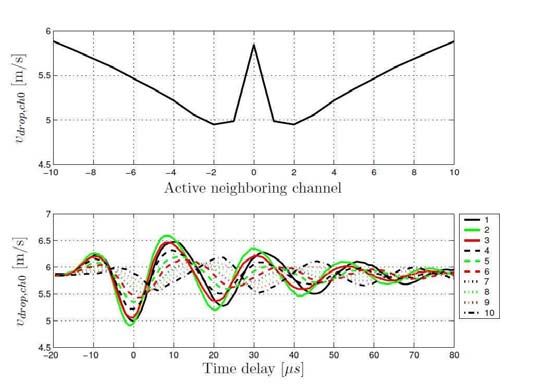
2010 IEEE International Conference on Control Applications
Part of 2010 IEEE Multi-Conference on Systems and Control
Yokohama, Japan, September 8-10, 2010

     Model-Free Optimization Based Feedforward Control for an Inkjet
                               Printhead
                                  M. Ezzeldin, P.P.J. van den Bosch, A. Jokic and R. Waarsing

   Abstract— Inkjet is an important technology in document                      pulse using a different physical principle. A piezoelectric
printing and many new industrial applications. As inkjet                        inkjet allows a wider variety of inks than a thermal one
developments are moving towards higher productivity and                         but the printheads are more expensive. Nowadays inkjet
quality, it is required to achieve small droplet size which is
fired at a high jetting frequency. Inkjet printers are now widely                developments are moving towards higher productivity and
used to form conductive traces for circuits, as well as color                   quality, requiring adjustable small droplet sizes fired at high
filters in LCD and plasma displays, what makes the printing                      repetition rates.
quality an important issue. In this paper, an optimization-based
feedforward control is proposed to improve the printing quality
of the piezoelectric inkjet printer. A novel optimized input pulse                 In this paper, the piezoelectric inkjet printer is considered.
is proposed and a model-free optimization is applied to obtain
the optimal parameters of the proposed pulse. The proposed
                                                                                The main goal is to improve the printing quality of the
optimal pulse is applied to the inkjet printhead and the system                 printhead by controlling and keeping both the speed
performance is investigated.                                                    and volume of the ink drop constant at different jetting
                                                                                frequencies.
                        I. INTRODUCTION
   Inkjet printers are non-impact printers that print text
                                                                                   Optimization of process performance is a natural choice
and images by spraying tiny droplets of liquid ink onto
                                                                                for reducing production costs, improving product quality, and
a medium (paper). Besides the well-known small inkjet
                                                                                meeting safety requirements and environmental regulations.
printers for home and office, there is a market for
                                                                                Process optimization is typically based on a process model
professional inkjet printers. All different inkjet applications
                                                                                that is used by a numerical procedure for computing the
have their own performance requirements. For professional
                                                                                optimal solution. However, in practical situations it is
printing applications, accuracy in terms of microseconds,
                                                                                difficult to find an accurate process model with affordable
micrometers and picoliters is desired. It is expected that for
                                                                                effort. Uncertainty results primarily from trying to fit a
future applications these criteria will become even tighter.
                                                                                model of limited complexity to a complex process system
Here, main targets are a high resolution, a constant quality
                                                                                (see e.g.[1] and [2]). The model-fitting task is further
and a high print speed. These demands can directly be
                                                                                complicated by the fact that process data are usually noisy
translated into small droplets with constant properties and
                                                                                and signals often do not carry sufficient information for
high jetting frequencies of the printhead.
                                                                                efficient process identification [3]. Therefore, optimization
                                                                                using an inaccurate model might result in suboptimal
   Currently, most inkjet printers use either thermal inkjet or
                                                                                operation or, worse, infeasible operation when constraints
piezoelectric inkjet technology. A thermal inkjet printer uses
                                                                                are present.
a heating element to heat liquid ink to form vapor bubbles,
which forces the ink droplets to leave the nozzle. Most
commercial and industrial inkjet printers use a piezoelectric                      A lot of efforts have been already done to produce
actuator in an ink-filled chamber behind each nozzle                             a good model for the ink channel [4], [5], however,
instead of a heating element. When a voltage is applied,                        this model is still rather incomplete. In this paper, an
the piezoelectric material changes its shape or size, which                     optimization-based model-free controller is proposed to
generates a pressure pulse in the fluid forcing a droplet                        improve the performance of the printhead. The model
of ink to leave the nozzle. This is, essentially, the same                      has been replaced by measurements and the optimization
mechanism as the thermal inkjet but it generates the pressure                   problem is formulated to minimize the error between the
                                                                                desired drop speed and the measured drop speed.
   This work has been carried out as part of the OCTOPUS project with
Océ Technologies B.V. under the responsibility of the Embedded Systems
Institute. This project is partially supported by the Netherlands Ministry of
Economic Affairs under the Bsik program.                                           The remainder of the paper is organized as follows. First,
   M. Ezzeldin, A. Jokic and P.P.J. van den Bosch are with the                  a system description is presented in Section II. Then, the
Department of Electrical Engineering, Eindhoven University of
                                                                                problem statement is discussed in Section III. Section IV
Technology, P.O. Box 513, 5600 MB Eindhoven, The Netherlands.
R. Waarsing is with Océ-Technologies B.V. m.ezz@tue.nl,                        presents the proposed optimization-based model-free con-
a.jokic@tue.nl,p.p.j.v.d.bosch@tue.nl and                                       troller design. Experimental results are given in Section V.
rene.waarsing@oce.com                                                           Finally, concluding remarks are collected in Section VI.

978-1-4244-5363-4/10/$26.00 ©2010 IEEE                                      967
Fig. 2.   Drop jetting mechanism

Fig. 1.    Exploded view of a piezoelectric inkjet printhead (left) and
schematic representation of a single channel (right).                           are around 2 to 3 picoliters. For some applications,
                                                                                it is required that the drop-size can be varied during
                                                                                operation. For example, for large areas that need to
                   II. S YSTEM DESCRIPTION                                      be covered large drops are desired, whereas for high
                                                                                resolution printing small drops are desirable. This is
   In this paper, we consider a piezoelectric inkjet printhead                  referred to as drop-size modulation.
which comprises two arrays of ink channels with a high                      •   Drop speed and volume consistency: The variations in
integration density. Each channel is equipped with its own                      drop volume and drop speed between successive drops
piezo-actuator and the printhead works according to the                         and between the nozzles must stay within a certain
Droplet-on-Demand (DoD) principle. In Fig. 1, an exploded                       range, to avoid irregularities in the printed object. In
view of the piezoelectric inkjet printhead is shown, together                   this paper, only drop-to-drop consistency is considered.
with a schematic representation of a single channel. To fire a               •   Productivity: The productivity of a printhead is mainly
droplet, a trapezoidal pulse is provided to the piezo-actuator                  determined by the jetting frequency, defined as the
as shown in Fig. 2. Then, ideally, the following occurs, see                    number of drops that a channel jets within a certain time,
e.g. [6] and [7]. First, a negative pressure wave is generated                  and the number of nozzles per inch (npi-ratio). These
in the channel by enlarging the volume in the channel. This                     two parameters are highly dependent on the specific
pressure wave splits up and propagates in both directions.                      design of printhead.
These pressure waves are reflected at the reservoir that                     •   Reliability: Reliability of the jetting process is one
acts as an open end and at the nozzle that acts as a closed                     of the most important performance requirements for
end. Note that the negative pressure wave reflecting at the                      printheads. In this context, reliability is defined as the
nozzle causes the meniscus to retract. Next, by decreasing                      absence of nozzle failure per a certain number of jetted
the channel’s volume to its original value, a positive                          drops, e.g. one failure per one million jetted drops.
pressure wave is superimposed on the reflected waves
exactly when they are located in the middle of the channel.                                III. P ROBLEM S TATEMENT
Consequently, the wave traveling towards the reservoir is                    Meeting the above described performance requirements
canceled, whereas the wave traveling towards the nozzle                   is severely hampered by several operational issues that are
is amplified such that it is large enough to result in a droplet.          associated with the design and operation of printheads.
                                                                          Major issues that are generally encountered are residual
   For most designs, the input pulse is manually shaped based             vibrations and cross-talk.
on physical insight into the working of a printhead. For the
design presented here, the actuation pulse is tuned to the first              After a drop is jetted the fluid mechanics within an ink
eigenfrequency of the ink channel. Additionally, somewhat                 channel are not at rest immediately, apparently traveling
more complex waveforms are designed for purposes like                     pressure waves are still present. In Fig. 3, the system
smaller droplets and constant drop speed. For a piezoelectric             response to a standard actuation pulse is depicted. Also, the
printhead, an important set of requirements is related to the             time instant of drop ejection is indicated (around 20 μ sec
resulting drop properties:                                                in Fig. 3). Usually, the fixed actuation pulse is designed
  •   Drop speed: The resulting droplets are required to have             under the assumption that a channel is at rest, which is
      a certain speed, typically around several m/s.                      clearly not true for about 100 to 150 μ sec (see Fig.3).
  •   Drop volume: Depending on the application under                     This limits the maximally attainable jetting frequency,
      consideration, the performance requirement concerning               having significant consequences concerning the productivity
      volume typically varies from 5 to 15 picoliters. Smaller            and drop consistency of a printhead. If the presence of
      drop volumes are for example required with the man-                 residual vibrations is ignored and the jetting frequency is
      ufacturing of PolyLEDs. The smallest drop volumes                   increased nonetheless, drop properties start varying. As an

                                                                      968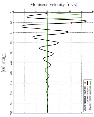
example, the so-called Droplet-on-Demand (DoD) speed
curve is depicted in Fig. 4, showing the dependency of the
drop speed on the jetting or DoD frequency. As shown,
considerable speed fluctuations result.
A second phenomenon that is encountered during
jetting is the interaction between different channels, called
cross-talk. The cross-talk originates from the fact that the
pressure waves within one channel influence the neighboring
channels. This type of cross-talk is called acoustic cross-
talk. Another source of the cross-talk is the deformation
of a channel itself. Since all piezo-fingers are connected
to a substrate, a deformation of one piezo-unit induces
a deformation of the neighboring units. As a result, the
volume of the neighboring channels changes too, which
induces pressure waves in those channels. The deformation
of the printhead structure can originate from two sources. Fig. 3. System response for the standard pulse
The first one is the result of a channel being actuated and
is referred to as direct voltage cross-talk. The second one
is the result of the occurring pressure wave that causes
deformation of the channel and is called indirect or pressure DoD curve
9
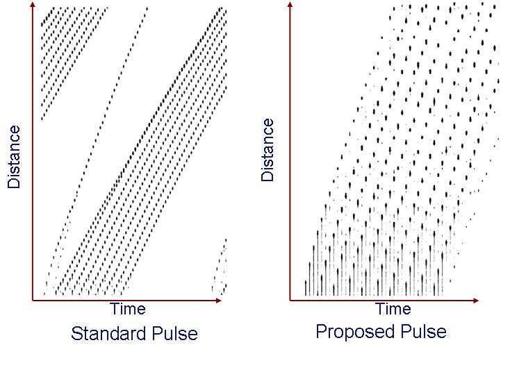
cross-talk. Fig. 5 shows the influence on the droplet speed
of the center channel of an array of 21 channels when 8
neighboring channels are active. As shown in the figure 7
when the direct neighbor (channel 1 or -1) becomes active,
Drop speed (m/sec)
6
a deviation of droplet speed of channel 0 occurred. It can
5
be observed that for channels which are located further
4
away, the influence of cross-talk decreases. Furthermore,
Fig. 5 indicates the influence of the cross-talk when a 3
different time delay between the actuation of channel 0 and 2
its neighbors is introduced. 1
0
Residual vibration and cross-talk result in a high variation 15 20 25 30 35 40 45 50 55 60
Jetting frequency (kHz)
in the drop speed and volume. In the current inkjet printers,
a fixed actuation pulse is used, which neglects the above Fig. 4. DoD curve
mentioned problems. Fig. 6 shows the jetting 5 drops from
one nozzle at different DoD frequencies. It is clear that
the drops have different speeds, which affect the printing
quality. Our main objective in this paper is to improve
the printing quality of the printhead by keeping both the
speed and volume of the ink drop constant. So, we want to
minimize the speed and volume variations that occur due to
the presence of the residual vibration and cross-talk.
The problem statement can be translated to the following
objectives:
1) Reducing the speed variations for each nozzle at each
jetting frequency.
2) Reducing the speed variations over all the jetting
frequencies (flat DoD curve).
In this paper, a new input pulse is proposed, see Fig.7, to
reduce the drop speed variations for one nozzle. The cross- Fig. 5. Influence on the droplet speed of channel 0 (center channel) by
talk effect is not considered in the pulse design. A model- actuation of different neighboring channels at the same time (upper plot)
and with a varying time delay between the channels (bottom plot).
free-optimization approach is proposed to obtain the optimal
parameters of the proposed pulse.
969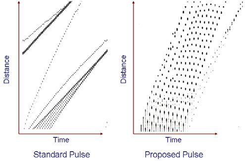
IV. O PTIMIZATION P ROCEDURE

   Feedback control is based on our ability to measure
or estimate the controlled variable. In the inkjet printer,
there are no sensors for online measurement for the
system variables; hence a feedforward controller is the
most appropriate solution. Although residual vibration and
cross-talk effects are large, they are lightly predictable and
reproducible. Hence, a model based feedforward controller
can be appropriate for this case. Given accurate knowledge
of the plant parameters, it seems straightforward to construct           Fig. 6.        Jetting 5 drops at different DoD frequencies.
feedforward controller as the inverse dynamics of the plant.
This is the Perfect Tracking Controller (PTC) strategy. A                  Vactuation

lot of efforts have been done to produce a good model for                                TA

the ink channel, however this model is still incomplete.
Moreover, the model of the jetting process is only partly
known.                                                                                  VA

   In this paper, we propose a new input pulse. As shown                                                       TrQ             Tf Q

in Fig.7, the new pulse consists of two pulses: an actuation                   Tr                 Tf     TdQ                          Time
                                                                                                                         VQ
pulse and quenching pulse. The actuation part is used to
formulate and jet the drop while the quenching part is                                                                    TQ
used to dampen the residual vibrations. The optimal pulse
parameters are calculated by minimizing the error between                                      Fig. 7.   New input pulse.
the actual drop speed and a desired drop speed. In this
approach the optimization is carried out on the real set-up
instead of using a printhead model. A schematic diagram of       T fQ : The quenching pulse fall time [μ sec],
the proposed approach is depicted in Fig.8.                      VQ : The quenching pulse amplitude [Volt],

   A high speed camera is used to record the time history          while the optimization cost function is
of the drops traveling from the nozzle plate to the paper.                               f =Fmax t=T
An image processing technique is developed to retrieve the
actual speed of each drop. First, the image is filtered to get
                                                                            J =               ∑ ∑ (vdesired − vactual (t, f ))2 ,            (1)
                                                                                         f =Fmin t=0
rid of the dots which represent satellites and keep only the                s.t. θmin ≤ θ ≤ θmax
droplets dots. Then, the image is converted into a binary
image which stores an image as a matrix but can only             where f is the jetting frequency, vdesired is the desired drop
color a pixel black or white (and nothing in between). It        speed, vactual is the actual drop speed, T denotes the total
assigns a 0 for black and a 1 for white. After that, a pattern   time of the experiment and t is the time instances when the
recognition technique is applied to obtain the positions         measurements are taken.
of each droplet and finally the speed of each droplet is          The optimal pulse which minimizes the cost function is given
calculated based on the droplet position and the traveling       by:
time.                                                                                            θopt = arg min J                            (2)
An optimization technique is used to get the optimal                                                                 θ
actuation pulse parameters by minimizing the error between       This problem formulation leads to a nonlinear optimization
the actual drop speed and a desired reference drop speed.        problem which can be solved by nonlinear optimization
The optimization problem is defined as follows.                   techniques. The optimization toolbox in Matlab is used to
The pulse parameters are (see Fig. 7)                            solve this problem. The fmincon function is used, which
                                                                 attempts to find a constrained minimum of a scalar function
    θ = [Tr TA T f VA TdQ TrQ TQ T fQ VQ ] with                  of several variables starting at an initial estimate. This is
Tr : The actuation pulse rise time [μ sec],                      generally referred to as constrained nonlinear optimization or
TA : The actuation time [μ sec],                                 nonlinear programming. To avoid trapping in local minima,
T f : The actuation pulse fall time [μ sec],                     the optimization problem is carried out several times using
VA : The actuation pulse amplitude [Volt],                       different initial values.
TdQ : The time delay between the actuation and quenching
pulses [μ sec],                                                  A. Experimental set-up
TrQ : The quenching pulse rise time [μ sec.],                       A schematic overview of the experimental set-up is de-
TQ : The quenching time [μ sec],                                 picted in Fig. 9. With this set-up, inkjet printheads can be

                                                             970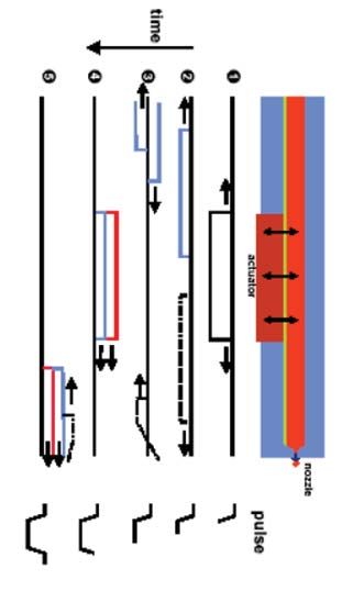
Fig. 9.   Experimental set-up.

    Fig. 8.   Model-free optimization feedforward control approach.
                                                                        DoD curve is the steady state speed of the drop at different
                                                                        jetting frequencies. It can be observed that the drop speed
                                                                        variation for the proposed pulse is less than 1.5 m/sec
investigated in various ways. The only actuator is the piezo-           compared with 6 m/sec in case of the standard pulse. The
unit of the inkjet printhead. Two sensors are available in this         proposed pulse can be used for jetting drops with a DoD
set-up:                                                                 frequency up to 56 kHz without overlapping of the pulse.
  i) The piezo-unit not only can be used as actuator but also           Note that the sudden change in the DoD curve at 56 kHz
     as sensor to measure the pressure waves in the channel             is due to that the waveform generator can not overlap the
     after jetting a droplet.                                           pulses.
 ii) A Charge-Couple Device (CCD) camera,equipped with
     a microscope, which is used to monitor the properties                 The second test is jetting 10 drops at different jetting
     of the resulting droplet                                           frequencies and analyzing the time history of the drop
A stroboscope provides a short light flash at a defined                   traveling form the nozzle plate to the paper. Figures 11-12
instant after the droplet is jetted and an image is obtained            show the time history of the 10 drops for both the proposed
with a snapshot at a droplet. Both the time duration and                and standard pulses at jetting frequencies 28 and 46 kHz
the distance that the droplet has traveled are known. By                respectively. The time history for the standard pulse shows
using this information, an estimate of the droplet speed                that the first drop is faster than the subsequent drops. On
can be obtained. Moreover, it is possible to estimate the               the other hand, using the proposed pulse shows that the
volume of the droplet, because the droplet diameter can                 drop speed of the 10 drops are almost the same. The drop
be determined. Other information which can be obtained                  speed of the 10 drops over jetting frequencies 20-70 kHz is
concern the droplet’s angle, the formation of satellites and            depicted in Fig.13.
the stability of the jet process.
                                                                          The maximum drop speed variation at each jetting fre-
   As depicted in Fig. 9, the set-up is connected to a personal         quency is calculated as
computer that is equipped with cards for image processing
                                                                                          Δv( f ) = vmax ( f ) − vmin ( f )          (3)
and communication. On the computer, the desired actuation
signals can be programmed and relevant data can be stored               The maximum drop speed variation is less than 1 m/sec for
and processed. After defining the actuation signal, it is sent           the proposed pulse while it is 2.5 m/sec for the standard
to a waveform generator. The waveform generator sends                   pulse. Fig. 14 shows the drop speed variations for the
the signal to an amplifier unit, which has a certain gain.               proposed and standard pulses.
From the amplifier unit, the signal is fed to a so-called
switch-board. The switch-board is controlled by the personal                                  VI. CONCLUSIONS
computer and determines which channels are provided with                   A new pulse has been proposed to improve the perfor-
the appropriate actuation signals. For the tracing of both the          mance of the inkjet printhead. A model-free optimization has
actuation and various sensor signals, an oscilloscope is used.          been used to obtain the optimal parameters of the proposed
This oscilloscope is connected to the computer and displayed            pulse. The three most prominent performance criteria for a
data can be downloaded to the personal computer.                        inkjet printhead are its productivity, drop-consistency, and
                                                                        stability. The focus of the research presented in this paper lies
                  V. E XPERIMENTAL RESULTS                              on the former two. The attainable performance with respect
   In this section, the proposed pulse is applied to a real             to these two issues is limited by two commonly encountered
printhead and the results are compared with a standard                  operational issues: residual vibrations and cross-talk. In this
pulse. Different tests have been carried out to evaluate the            paper, it has been demonstrated that feedforward control is a
efficiency of the proposed pulse. Fig. 10 shows the DoD                  suitable control strategy to overcome the residual vibrations
curve for the proposed pulse and the standard pulse. The                and hence increase the performance of inkjet printheads

                                                                      971
Jetting 10 drops at different DoD Frequencies
8
DoD curve
9 7
Overlapping part
8
6
7
Drop speed (m/sec)
1st drop
5
2nd drop
6
Drop speed (m/sec)
3rd drop
4
5 4th drop
5th drop
3
4 6th drop
7th drop
3 2
8th drop
9th drop
2 1 10th drop
1 Proposed pulse (Max. deviation=1.5m/sec)
0
Standard pulse (Max. deviation=6m/sec) 20 25 30 35 40 45 50 55 60 65 70
0 Jetting frequency (kHz)
15 20 25 30 35 40 45 50 55 60
Jetting frequency (kHz)
Fig. 13. Jetting 10 drops at different DoD frequencies (20-70 kHz).
Fig. 10. Optimized DoD curve.
Maximum drop speed variation
3
Proposed pulse
Standard pulse
2.5
Max. drop speed deviation (m/sec)
2
1.5
1
0.5
0
20 25 30 35 40 45 50 55 60 65 70
Jetting frequency (kHz)
Fig. 14. Maximum drop speed variation at different DoD frequencies (20-
70 kHz).
Fig. 11. Jetting 10 drops at DoD frequency 28 kHz.
considerably beyond current limits. The experimental results
have shown the efficiency of the proposed pulse.
R EFERENCES
[1] D. Bonvin, ”Optimal operation of batch reactors-A personal view”,
Journal of Process Control, vol. 8, 1998, pp 355-368.
[2] J.F. Forbes and T. E. Marlin, ”Model accuracy for economic opti-
mizing controllers: The bias update case”, Industrial and Engineering
Chemistry Research, vol. 33, 1994, pp 1919-1929.
[3] W.S. Yip and T. E. Marlin, ”The effect of model fidelity on real-time
optimization performance”, Computers and Chemical Engineering, vol
28, pp 267-280, 2004.
[4] H.M.A. Wijshoff, Structure- and fluid-dynamics in piezo inkjet print-
heads,PhD thesis, 2008.
[5] M. B. Groot Wassink, Inkjet printhead performance enhancement by
feedforward input design based on two-port modeling, PhD thesis,
2007.
[6] D. B. Bogy and F. E. Talke, ”Experimental and theoretical study
of wave propagation phenomena in drop-on-demand inkjet devices”,
IBM Journal of Research and Developement, vol. 28, pp. 314-321,
1984.
[7] B. V. Antohe and D. B. Wallace, ”Acoustic phenomena in a demand
Fig. 12. Jetting 10 drops at DoD frequency 46 kHz. mode piezoelectric inkjet printer”, Journal of Image Science and
Technology, vol. 46, pp. 409-414, 2002.
972You can also read