Twisting, Tearing and Flicking Effects in String Animations
←
→
Page content transcription
If your browser does not render page correctly, please read the page content below

Twisting, Tearing and Flicking Effects in String
                   Animations

 Witawat Rungjiratananon1 , Yoshihiro Kanamori2 , Napaporn Metaaphanon3 ,
          Yosuke Bando4 , Bing-Yu Chen5 , and Tomoyuki Nishita1
                               1
                                 The University of Tokyo
                                   2
                                  University of Tsukuba
                                    3
                                      Square Enix
                               4
                                 TOSHIBA Corporation
                           5
                               National Taiwan University

      Abstract. String-like objects in our daily lives including shoelaces, threads
      and rubber cords exhibit interesting behaviors such as twisting, tearing
      and bouncing back when pulled and released. In this paper, we present
      a method that enables these behaviors in traditional string simulation
      methods that explicitly represent a string by particles and segments. We
      offer the following three contributions. First, we introduce a method for
      handling twisting effects with both uniform and non-uniform torsional
      rigidities. Second, we propose a method for estimating the tension acting
      in inextensible objects in order to reproduce tearing and flicking (bounc-
      ing back); whereas the tension for an extensible object can be easily
      computed via its stretched length, the length of an inextensible object
      is maintained constant in general, and thus we need a novel approach.
      Third, we introduce an optimized grid-based collision detection for an
      efficient computation of collisions. We demonstrate that our method al-
      lows visually plausible animations of string-like objects made of various
      materials and is a fast framework for interactive applications such as
      games.

1   Introduction

String-like deformable objects play an important role to represent hair strands,
threads, elastic rods, cables and ropes in computer graphics. For realistic ani-
mations of such objects, we have to reproduce their interesting behaviors such
as bending, stretching, twisting, tearing and flicking when pulled and released,
according to their material properties. For example, threads are made of yarn
that is barely stretched but easy to tear. An elastic rod made of rubber can be
twisted and flicked but hard to break. A cable that has non-uniform density dis-
tribution within its cross-section or a partially braided rope such as fourragère
has a non-uniform torsional rigidity. In the rest of this paper, we refer to such
string-like objects as strings.
    To simulate a string, several traditional methods can be used such as mass-
spring systems [13,15], rigid multi-body serial chains [7], geometric approaches [12,
2

14] and elastic energy-based models [2, 3, 17]. However, all behaviors (twisting,
tearing and flicking) of a string are not introduced together in a single framework
by these methods.
    Handling of inextensible strings, such as threads and cables, poses another
technical challenge. To prevent inextensible strings from excessive elongation,
many length-constraint schemes called strain limiting have been developed. With
strain limiting, however, the tearing simulation becomes difficult; whereas an
extensible string will break when its length or strain reaches a certain break-
ing point, we cannot see when an inextensible string will tear based on the
constrained length. Moreover, beside the fact that an inextensible string is not
elongated by their own weight, under a large applied force such as a large pulling
force, the string should be elongated according to its material property. However,
the strain limiting causes the material property unrelated to the applied force.
    In this paper, we present a method that can handle twisting, tearing and flick-
ing of strings in real-time. Our method is a simple pseudo-physically-based model
which is easy to implement, yet visually plausible results can still be achieved.
Our method is applicable to traditional simulation methods that explicitly rep-
resent a string by particles and segments. Our implementation is based on Chain
Shape Matching (CSM) [14], which is a simplified version of the more versatile
deformation method, Lattice Shape Matching (LSM) [12], since CSM inherits
and enhances several advantages of LSM (e.g. CSM is fast, easy to implement
and numerically stable). Specifically, we offer the following three contributions:
 1. We introduce a simple method for twisting effects by adding twisting angles
    into each segment in a string which can handle both uniform and non-uniform
    torsional rigidities (Sec. 4).
 2. We propose a method for estimating the tension for tearing and flicking
    effects in an inextensible string whose actual stress and strain values are
    constrained from the strain limiting (Sec. 5).
 3. We introduce a collision searching scheme for efficient collision handling using
    a grid-based data structure which has a less number of neighbors to be
    searched compared to typical searching schemes. (Sec. 6).

2   Related Work
Simulation of twisting strings: Many researches on the twisting effect in
string simulation introduced various models for solving the Cosserat and Kirch-
hoff energy equations. Bertails et al. [3] introduced a mechanical model called
super helices for simulating human hair based on the Kirchhoff theory. However,
handling collision responses is not straightforward due to the implicit repre-
sentation of hair strands. Spillmann and Teschner [17] explicitly represented the
centerline of an elastic string and used the finite element method (FEM) to solve
the Cosserat energy equation. Recently, Bergou et al. [2] introduced a discrete
model for simulating elastic strings based on the Kirchhoff theory. However, the
twisting angles are computed using quasi-static assumption, thus the twisting
of non-uniform torsional rigidity along the string is not addressed. There are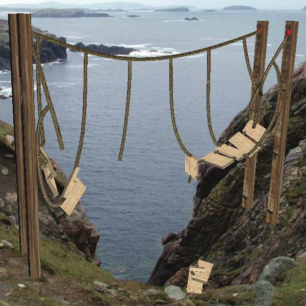
3

                                                              twisting angle θi
                   segment particle               segment i
          region

                               wCSM                           twist-free frame
                                                              material frame

                     (a)                             (b)

Fig. 1. Our string model. (a) Multiple overlapping chain region in CSM. (b) A twisting
angle of a segment of an elastic string is an angle between a twist-free frame and a
material frame.

also several works on pseudo-physical models that can capture the twisting ef-
fect without solving the energy equations. Hadap [7] introduced a model for
capturing the torsion effect by integrating a torsion spring into each joint of
rigid links. However, strings cannot be stretched and collision handling is not
straightforward, because motion is propagated from top to bottom in one sin-
gle pass (not affect backward). Selle et al. [15] represented a hair strand by a
chain of tetrahedrons of springs and captured the torsion effect by introducing
appropriate altitude springs. However, the configuration of springs is complex,
auxiliary particles are required along a string.
Strain limiting for inextensible strings: In order to handle inextensible ob-
jects simulated by deformation models, a variety of methods for stretch resistance
have been continuously proposed; from Provot’s iterative post-processing edge
constraint [11], to a more recent constraint method based on impulse [5]. Some
alternative ways of stabilizing stiff simulation were also proposed [1,6,10]. These
methods, and many of their sequels, have a common goal to limit the maximal
strain to a certain threshold. Accordingly, these kinds of methods are problem-
atic in case of excessive stretch or when rupture should occur. Metaaphanon et
al. [9] proposed a method to deal with cloth tearing using a mass-spring model.
However, it tears cloth by checking lengths of springs; when and where yarns of
cloth are cut were not directly related to user-applied external forces and cloth
material properties, but dependent on how the method constrains the springs.

3    Chain Shape Matching (CSM)

Before describing the details of our algorithms, this section first briefly introduces
Chain Shape Matching (CSM) [14], the basis model used in this paper. In CSM,
a string is represented as a chain of particles connected by segments (see Fig. 1
(a)). The particles are grouped into multiple overlapping chain regions with the
region half-width wCSM ∈ {1, 2, 3, . . .}. The chain region half-width corresponds
to the stiffness of the string. The particles are independently moved by external
forces, and then an optimal rigid transformation (i.e., rotation and translation)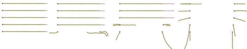
4

                        wtwist
                                      region r                                              region r
    twist    θt
                                                         twist            Δθi

clamped                                     clamped   clamped                                     clamped
             material frame (t+1)                                          material frame (t+2)
            material frame (t)              (a)                           material frame (t+1)    (b)

Fig. 2. (a) An elastic string clamped at both ends is twisted at one end with a twisting
angle θt . (b) The increment of the twisting angle is propagated to next segments.

of each region is computed. The rigidly-transformed positions of the particles
are called goal positions. The goal position of each particle is weighed in the
overlapping regions by particle per-region mass. Finally, each particle is updated
toward the goal position.

4      Twisting Effects
Based on CSM, a string in our model is represented as a chain of (n+1) particles
connected by n segments (Fig. 1 (a)). A segment i ∈ {1, 2, . . . , n} has a twisting
angle θi tracking how much the segment is twisted. The twisting angle can be
represented as an angle between a twist-free frame (bishop frame) and a material
frame (Fig. 1 (b)). In the initial state, we specify an initial angle θi0 of each
segment i according to the shape of the string. The twisting angle is assigned
for each segment, not for each particle, to avoid the ambiguity.
    The behavior of twisting can be clearly observed when a string clamped at
both ends is twisted at one end. Therefore, we use this scenario for our expla-
nation (Fig. 2). When we twist one clamped end with an angle θt , the angle
θi of the segment is increased. The increment of the twisting angle of the seg-
ment is propagated to the next segments in order to minimize the elastic energy.
We compute a goal twisting angle for each segment, similarly to finding a goal
position for each particle in shape matching.
    First, we group the segments into multiple overlapping chain regions with
the region half-width wtwist ∈ {1, 2, 3, . . .} which affects the propagation speed
of twisting angles in the string; the larger the wtwist is, the faster the change of
twisting angles is propagated. The size of each region in a string can be varied for
handling non-uniform torsional rigidity. The twisting angle increment ∆θkregion
of each region k is computed by averaging the ∆θj = θj − θj0 weighted by mass
mj for the set of segments within the region Sk :
                                        X
                                              (θj − θj0 )mj
                                                  j∈Sk
                                    ∆θkregion =          X            .                                 (1)
                                                                 mj
                                                         j∈Sk

Then, θi of each segment i is updated with the twisting angle increment ∆θisegment .
The goal twisting angle increment ∆θisegment is calculated by summing the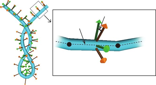
5

∆θkregion of each region k that segment i belongs to:
                                       X
                          ∆θisegment =     ∆θkregion ,                            (2)
                                          k∈ℜ

                                    θi ← θi + ∆θisegment ,                        (3)

where ℜ is a set of regions that segment i belongs to. The twisting force fitwist
can be treated as an external force to particle i and derived from elastic energy
equation [2] as follows:

                        β                            −κbi+1 − κbi−1
                fitwist =  (θi+1 − 2θi + θi−1 )(                    ),            (4)
                        L                                  2l
                                ei−1 × ei
                  κbi = 2                          ,                              (5)
                          |ei−1 ||ei | + ei−1 · ei

where κbi is the curvature binormal, ei is the segment vector, l is the length of
the segment, β is the twisting stiffness of the string and L is the total length of
the string.

5     Tearing and Flicking Effects
This section briefly reviews the material science of a string, and then describes
strain limiting, a technique to constrain the length of an inextensible object.
Finally, we describe the way to estimate the tension in an inextensible string in
order to handle tearing and flicking.

5.1    Stress and Strain
In material science, the strength and elongation of a string is associated with its
stress-strain curve [4]. The stress σ of a string is the average force per unit area
of a cross-section surface:
                                         kFn k
                                    σ=         ,                                  (6)
                                          A
where A is the cross-sectional area and Fn is the normal force. The total force
acts on the cross-section surface in the surface normal direction. The strain ε of
a string is expressed as the ratio of the elongation ∆L to the initial length L0 of
the string:
                                    ∆L   L − L0
                               ε=      =        ,                                 (7)
                                    L0     L0
where L is the current length of the string.
    Along the curve, the material exhibits elastic behaviors until the yield point;
prior to the yield point the material will return to its original shape if the applied
force is removed. The slope of this elastic region is the Young’s modulus E = σ/ε.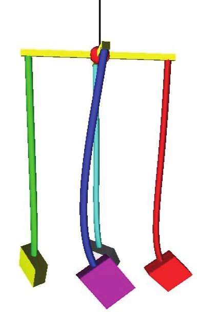
6

                         fixed
                                                           force
                   (a)
                                        time step                      force
                   (b)

                                    length constraint      force
                   (c)
                                 tension in each segment           equivalent result
                                                           force
                   (d)
                                                    Ti

Fig. 3. A simple example of the tension computation. From (a) to (c), an ordinary
length-constrained string simulation is performed. The tensions make the particles
move from their unconstrained positions to the constrained positions in (d), yielding
an equivalent result for (c).

Once the yield point is passed, the material becomes plastic; some fractions of
the deformation will be permanent and non-reversible. As deformation continues,
the material will break when the stress or strain reaches the rupture point.
    The stress-strain curve can be derived via a strength testing of a material
sample stored as a data set of the experimental result. However, the stress-
strain curve of most materials in the elasticity state is linear with the Young’s
modulus as its slope. Therefore, the part of the curve from the origin to the yield
point can be stored as a constant value. Still, the data set is required for the
curve in the plasticity state. In our implementation, we simply approximate the
curve by a line with a constant slope that fits the curve best. As a result, our
implementation uses two constant values to represent the stress-strain curve in
elasticity and plasticity states together with two constants for yield point and
rupture point.

5.2   Strain Limiting

To prevent segments from stretching excessively, position constraints are imposed
so that the length of each segment i does not exceed a certain threshold Lmaxi   .
Since correcting the length of one segment may change the length of other seg-
ments, iterative adjustment is required. Each constraint is solved independently
one after the other as done in [10].

5.3   Tension Estimation

As previously stated, due to the constraint on lengths unrelated to applied forces,
actual stress and strain values cannot be directly computed from the simulation
result. Here we propose a novel approach to estimate the actual stress and strain
values for inextensible strings.
   The actual stress and strain values can be computed by estimating the ten-
sions in the string. To derive the tensions, we also consider the particle positions
computed without strain limiting. We model the tension Ti of a segment i as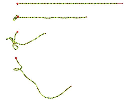
7

                          stress σ
                                     σrupture      rupture point

                                            yield point

                                                           σ
                                        Young’s modulus E= ε

                                                              strain ε

                    Fig. 4. Typical stress-strain curve of a string.

a stiff force that makes its particles i and i + 1 at both ends move from their
unconstrained positions x′i and x′i+1 (Fig. 3 (b)) to the constrained positions xi
and xi+1 (Fig. 3 (c)). In our implementation, we compute the tension as follows:

                    Ti = kstif f (kx′i+1 − x′i k − kxi+1 − xi k)ti ,                (8)

where kstif f is a coefficient and ti is an unit vector from particle i to i + 1.
The tension derived this way is used to reproduce tearing and flicking as well as
plastic behaviors of a string, as described in Sec. 5.4.

5.4   Tearing and Flicking a String

For tearing computation, we assign a rupture point or a stress threshold σrupture
for each segment. If segment’s stress exceeds its stress threshold, the segment
will be broken. The applied stress σi can be computed from tension Ti in each
segment using Eq. (6) with Fn = Ti .
    Similarly, we can handle the behavior of flicking using the tension. When
an inextensible string is pulled and released or torn apart, the applied stress is
vanished but the strain of the segment from the elongated length still remains.
The bouncing back force can be computed from an internal stress translated from
the strain by referencing the stress-strain curve (Fig. 4). However, the elongated
length is computed from the tension, i.e., we can directly use the tension as the
bouncing back force. Note that, without this technique, the string will just fall
down quietly by the gravity force because the elongated length is very small.
    As can be seen in the stress-strain curve (Fig. 4), a real string is lengthened
according to the stress in the elasticity and plasticity states prior to the rupture
point. Therefore, the maximum length Lmax        i    of each segment used in strain
limiting (Sec. 5.2) should be updated accordingly (otherwise the string does not
elongate). For this, we look up strain εi corresponding to applied stress σi from
the stress-strain curve, and use it to compute the appropriate value of Lmax        i
using Eq. (7), Lmax
                 i    = εi L0 + L0 . In the elasticity state, the strain εi of a string
becomes zero when applied forces are removed. However, when its strain exceeds
the yield point (plasticity state), εi is still the same as the last time the forces are
applied. Our method also modifies the radius of a segment in order to preserve
the volume of the segment when stretched.
8
g
a particle B
particle A f
b
e
c d
Fig. 5. A 2D example of our optimized searching scheme. When doing a collision
detection between particles A and B, segment collision tests between ag, af , bg and bf
capsules are tested.
6 Collision Handling
In this section, we introduce an optimized searching scheme for collision detec-
tion of strings. Previous works often use techniques based on bounding volume
hierarchy (BVH) [15, 16, 18] for collision detection of strings. Apart from BVH,
space partitioning using a grid-based data structure is a simple and efficient
technique for collision detection of strings which have a large number of self-
collisions. Specifically, we treat the segments as capsules and search for capsule
collision pairs. For neighbor searches, we use a uniform grid of voxels. The num-
ber of voxels to be searched is 27 (= 3×3×3) in a naı̈ve approach. For better
performance, we found that it suffices to search for colliding segments in only
seven neighboring voxels (top, bottom, left, right, front, back and center voxels)
under the following three specifications.
– Specifying the voxel size equal to or larger than segment length l
– Storing indices of particles in each voxel
– Searching for capsule collision pairs from two adjacent segments of each
particle in the seven neighboring voxels
For a better understanding, we describe using an example in 2D (five neighboring
cells). The idea can be generalized to the 3D case in a straightforward manner. In
Fig. 5, particles A and B are neighbors. Our method does the segment collision
test between their two adjacent segments, i.e., pairs of segments ag, af , bg and
bf . If two segments have an intersection, there is definitely a pair of particles
at their both ends in the seven neighboring voxels that the intersection can
be searched, even the intersection of segments is outside the seven neighboring
cells. This could be easily proved, if one writes all possible cases in 2D with five
neighboring cells (center, up, down, left and right).
The closest points of a pair of colliding segments i and j are indicated by
fractions s ∈ [0, 1] and t ∈ [0, 1], respectively. In order to move the colliding
segments to the non-intersection positions, we compute a displacement vector
between the closest points. Then, we move the both-end particles of each segment
corresponding to the fractions s and t similar to [18].
Moving a colliding segment may make the string discontinuous, and thus
we repeat shape matching until particle positions converge. Conversely, shape9
(b)
(d)
(e)
(a) (c)
Fig. 6. Our simulation results of twisting effects. (a) The twisting effect of a string
clamped at both ends. The string is gradually twisted on the left end and finally
twisted to form a loop. (b) A twisted string that forms a spiral shape like a telephone
cord. (c) An application for a hanging mobile in wind forces. (d) A string with uniform
torsional rigidity. (e) A string with non-uniform torsional rigidity.
matching may cause a collision again. As a result, iterations are required for both
shape matching and collision constraints. To lessen the iterations, we temporarily
make the masses of colliding particles heavier so that shape matching barely
moves the particles. In our experiments, by making the colliding particles three
times heavier, only one iteration suffices.
7 Results
Our implementation was written in C++ with OpenGL. All experiments were
conducted on a desktop PC with an Intel Core i7 3.20GHz CPU and 6GB RAM.
Fig. 6 shows the results of our twisting simulation. The twisting of strings
can reproduce phenomena such as an instability of bending and twisting called
buckling which makes a string to form a spiral shape (Fig. 6 (a) and (b)). An
application for a hanging mobile is also presented. In Fig. 6 (c), objects at the tips
of strings are rotated by wind forces and the strings are twisted. With twisting
effects, the strings twist back to the rest state, making the objects rolling back
and forth. Fig. 6d and Fig. 6e show the twisting of strings with uniform and
non-uniform torsional rigidities, respectively. The twisting angles in the string
with non-uniform torsional rigidity are distributed more equally in the larger
cross-section. Fig. 7 shows the tearing simulation results with the variation of
rupture thresholds. The rupture threshold is assigned to all segments in the
string. However, that kind of completely uniform strength is impossible in real
string. Our method randomly alters the rupture threshold in each segment with
the range of variation up to 0.01%. Please see the supplemental video for more
variation tests. Animation sequences of flicking are shown in Fig. 8. Without10
flicking, the string in Fig. 8 (a) falls naturally when an applied force is removed.
The string in Fig. 8 (b) bounces back by the tensions when the applied force
is removed. When the twisted string in Fig. 8 (c) is pulled and released, the
twisting effect also occurs. Fig. 9 shows simulation results of a destruction of a
hanging bridge. Wooden boards (rigid bodies) are tied with strings (ropes in this
case) to build the bridge. The ropes are gradually torn apart from collisions of
the wooden boards and incoming crates which cause high tensions in the ropes.
We used particle-based simulation method [8] for rigid body simulation in our
implementation. The video of our results can be found in the following link:
http://nis-lab.is.s.u-tokyo.ac.jp/~witawat/rod/stringAnimation.mov
The breakdown computational time in each process for strings with a different
numbers of particles is shown in Table 1. The strings in Fig. 6 (a), (b) and (c)
consist of 100, 100 and 200 segments respectively, while each string in Fig. 7
and 8 has 150 segments. The number of segments in Fig. 9 is 746 segments. The
computational time of the result in Fig. 9 is measured excluding the time for
rigid body simulation.
Limitations : Our method has some limitations. As previously mentioned, our
method is not a full physically-based model, thus, more advance physics behav-
iors such as spring-twisting pendulum and anisotropic bending in [2] are hard
to generate. The rapid motion of strings could cause the strings to pass through
each other or themselves. However, the problem did not occur in our experiments.
In case of rapid motion, continuous collision detection should be considered.
8 Conclusion and Future Work
We have introduced a simple model for simulating twisting, tearing and flick-
ing of strings, which is fast, easy to implement and applicable to traditional
simulation models. We have demonstrated that our method can handle twisting
effects of strings with both uniform and non-uniform torsional rigidities. Using
our method, the tension in an inextensible string can be estimated for generating
tearing and flicking effects. A variation in the quality of strings can be achieved.
Whilst our method is not physically-based, it can successfully reproduce the in-
teresting behaviors of strings that would greatly enrich the realism of interactive
applications such as games.
The collision between segments is treated as a collision between rigid seg-
ments. We would like to improve the collision detection algorithm to handle the
collisions between deformable segments. We also would like to improve an overall
performance with a GPU implementation.
9 Acknowledgement
We gratefully thank the anonymous reviewers for helpful comments. This work
was supported by Grant-in-Aid for JSPS Fellows (22·4748).11
(a) (b) (c) (d)
Fig. 7. Tearing simulation results of five strings with rupture thresholds. Rupture
thresholds of strings are varying, increasing from bottom to top. The rupture thresh-
old in each segment of the string is randomly altered with the range of variation up to
0.01%. As expected, the bottommost string, which had the lowest rupture threshold,
was torn first at the weakest point as animation sequences from (a) to (d).
(a) Animation sequences of (b) Animation sequences of (c) Animation sequences of
a string without flicking a string flicking a twisted string flicking
Fig. 8. Flicking animation sequences of strings from top to bottom.
Table 1. The computational time in milliseconds of each process in one time step. The
time step in our implementation is 0.01 second.
No. Time CSM Twisting comp. Tension est. Collision Total
of segments integration (Sec. 3) (Sec. 4) (Sec. 5) handling time
(Sec. 6)
100 0.011 0.086 0.098 0.221 1.31 1.73
150 0.022 0.168 0.184 0.424 1.36 2.16
200 0.029 0.221 0.237 0.564 1.37 2.42
746 0.128 0.501 0.739 1.67 3.13 6.17
References
1. Baraff, D., Witkin, A.: Large steps in cloth simulation. In: ACM SIGGRAPH 1998
Conference Proceedings. pp. 43–54 (1998)
2. Bergou, M., Wardetzky, M., Robinson, S., Audoly, B., Grinspun, E.: Discrete elastic
rods. ACM Transactions on Graphics 27(3), 63:1–63:12 (2008), (SIGGRAPH 2008
Conference Proceedings)
3. Bertails, F., Audoly, B., Cani, M.P., Querleux, B., Leroy, F., Lévêque, J.L.: Super-
helices for predicting the dynamics of natural hair. ACM Transactions on Graphics
25(3), 1180–1187 (2006), (SIGGRAPH 2006 Conference Proceedings)
4. Bhuvenesh, C.G., Rajesh, D.A., David, M.H. (eds.): Textile sizing. CRC Press.
(2004)12
Fig. 9. Animation sequences of a hanging bridge colliding with incoming crates.
5. Diziol, R., Bender, J., Bayer, D.: Volume conserving simulation of deformable bod-
ies. In: Eurographics 2009 Short Papers. pp. 37–40 (2009)
6. Goldenthal, R., Harmon, D., Fattal, R., Bercovier, M., Grinspun, E.: Efficient
simulation of inextensible cloth. ACM Transactions on Graphics 26(3), 49:1–49:8
(2007), (SIGGRAPH 2007 Conference Proceedings)
7. Hadap, S.: Oriented strands: dynamics of stiff multi-body system. In: Proceedings
of the 2006 ACM SIGGRAPH/Eurographics Symposium on Computer Animation.
pp. 91–100 (2006)
8. Harada, T.: Real-time rigid body simulation on GPUs. In: GPU Gems 3, chap. 29,
pp. 123–148 (2007)
9. Metaaphanon, N., Bando, Y., Chen, B.Y., Nishita, T.: Simulation of tearing cloth
with frayed edges. Computer Graphics Forum 28(7), 1837–1844 (2009), (Pacific
Graphics 2009 Conference Proceedings)
10. Müller, M., Heidelberger, B., Hennix, M., Ratcliff, J.: Position based dynamics.
Journal of Visual Communication and Image Representation 18(2), 109–118 (2007)
11. Provot, X.: Deformation constraints in a mass-spring model to describe rigid cloth
behavior. In: Graphics Interface 1995 Conference Proceedings. pp. 147–154 (1995)
12. Rivers, A.R., James, D.L.: FastLSM: fast lattice shape matching for robust real-
time deformation. ACM Transactions on Graphics 26(3), 82:1–82:6 (2007), (SIG-
GRAPH 2007 Conference Proceedings)
13. Rosenblum, R.E., Carlson, W.E., Tripp, E.: Simulating the structure and dynamics
of human hair: Modeling, rendering and animation. The Journal of Visualization
and Computer Animation 2(4), 141–148 (1991)
14. Rungjiratananon, W., Kanamori, Y., Nishita, T.: Chain shape matching for simu-
lating complex hairstyles. Computer Graphics Forum 29(8), 2438–2446 (2010)
15. Selle, A., Lentine, M., Fedkiw, R.: A mass spring model for hair simulation. ACM
Transactions on Graphics 27(3), 64:1–64:11 (2008), (SIGGRAPH 2008 Conference
Proceedings)
16. Sobottka, G., Weber, A.: Efficient bounding volume hierarchies for hair simulation.
In: Proceedings of the 2nd Workshop on Virtual Reality Interactions and Physical
Simulations. pp. 1–10 (2005)
17. Spillmann, J., Teschner, M.: CORDE: Cosserat rod elements for the dynamic sim-
ulation of one-dimensional elastic objects. In: Proceedings of the 2007 ACM SIG-
GRAPH/Eurographics Symposium on Computer Animation. pp. 63–72 (2007)
18. Spillmann, J., Teschner, M.: An adaptive contact model for the robust simulation
of knots. Computer Graphics Forum 27(2), 497–506 (2008), (Eurographics 2008
Conference Proceedings)You can also read