PHYSICAL REVIEW ACCELERATORS AND BEAMS 23, 012401 (2020)
←
→
Page content transcription
If your browser does not render page correctly, please read the page content below
PHYSICAL REVIEW ACCELERATORS AND BEAMS 23, 012401 (2020)
      Editors' Suggestion

                                      dc septum magnet based on permanent magnet
                                             for next-generation light sources
                      Tsutomu Taniuchi ,1,* Takahiro Watanabe ,1,2 Shiro Takano ,1,2 Tsuyoshi Aoki,1
                  Kenji Fukami,1,2 Shinichi Matsubara ,1 Kenichi Yanagida,1 Kazuhiro Hamato,3 Jun Kataoka,3
                                   Kanichiro Ogata,3 Yoshiyuki Saito,3 and Kunihiro Kusano3
                  1
                      Japan Synchrotron Radiation Research Institute (JASRI), 1-1-1 Kouto, Sayo, Hyogo 679-5198, Japan
                                2
                                  RIKEN SPring-8 Center (RSC), 1-1-1 Kouto, Sayo, Hyogo 679-5148, Japan
                                   3
                                    TOKIN Corporation, 6-7-1 Koriyama, Taihaku, Sendai 982-0003, Japan

                                             (Received 11 October 2019; published 2 January 2020)

                     This paper presents a dc septum magnet based on a permanent magnet that we developed as an injection
                  magnet for next-generation light sources. Permanent-magnet based magnet devices are regarded as one of
                  the key technologies for next-generation light sources as they are expected to consume less power, occupy
                  less space, and cause fewer failures than conventional electromagnets that require power sources. The
                  injection magnets, including the dc septum magnet, are often restricted to a limited space, and consume
                  large amounts of power. Thus, the advantage of building such a magnet using a permanent magnet should
                  be as important as that of building main magnets. We designed and fabricated a permanent-magnet based
                  dc septum magnet with a thin septum plate of 7 mm thickness, and confirmed that the measured gap and
                  leakage fields agreed well with the design values. The permanent-magnet specific issues such as a variable-
                  field mechanism, demagnetization and temperature dependence, are also solved. Furthermore, we explored
                  the numerical study for reducing the septum thickness, and verified that the double-septum structure
                  enabled a reduction in the overall septum thickness, while keeping adequate magnetic shielding.

                  DOI: 10.1103/PhysRevAccelBeams.23.012401

                          I. INTRODUCTION                                and combined-function bending magnets, as well as normal
                                                                         bending magnets [12]. In these studies, we proposed what
   One of the new features of next-generation light sources
                                                                         we call outer and inner plates for smoothly tuning the
compared with the third generation ones is the use of
permanent magnets (PMs) for the magnets in their mag-                    magnetic flux density on the beam axis, and also introduced
netic lattice, such as bending magnets of a storage ring                 Fe-Ni alloys for compensating the temperature dependence
[1–3]. A PM consumes less power than electromagnets,                     of the PM. To prevent demagnetization due to radiation
and its compactness due to a lack of coils can be beneficial             exposure, a samarium-cobalt (Sm2 Co17 ) magnet was
in cases where the packing factor is high. Moreover,                     chosen and the permeance coefficient was set as high as
accidental beam trips due to power supply failures are                   possible. In the present work, we designed and fabricated a
expected to be reduced significantly because these magnets               PM-based septum magnet, which should act as a functional
do not require any electric feed. These features may match               substitute for a dc septum electromagnet in the beam
requirements for future light sources, where the lattice                 injection part of future light sources.
consists of many strong magnets. Furthermore, stability                     A new off-axis beam injection scheme, in-vacuum
and reliability are important factors for user facilities. In            transparent off-axis beam injection [13], proposed for the
fact, a variety of magnets based on the PM have been                     SPring-8 upgrade, SPring-8-II [1], is shown in Fig. 1.
proposed, developed, and evaluated [4–11].                               A PM-based dc septum magnet was chosen considering
   At SPring-8, we designed and fabricated several types of              its spatial constraint and other advantages compared with
PM-based dipole magnets, such as the longitudinal gradient               electromagnet systems. The PM-based dc septum magnet is
                                                                         expected to provide a stable magnetic field free of power
                                                                         supply output variations and enables the stable beam
  *
      ihcuinat@spring8.or.jp                                             deflection necessary for the small injected beam oscillation
                                                                         amplitude, for both stacking and maintaining, by topping-
Published by the American Physical Society under the terms of            up the required beam intensity.
the Creative Commons Attribution 4.0 International license.
Further distribution of this work must maintain attribution to
                                                                            The challenge of developing a PM-based dc septum
the author(s) and the published article’s title, journal citation,       magnet is to have a strong magnetic field that deflects the
and DOI.                                                                 incident beam and minimize the leakage magnetic field for

2469-9888=20=23(1)=012401(9)                                      012401-1              Published by the American Physical Society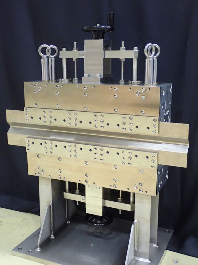
TSUTOMU TANIUCHI et al.                                                     PHYS. REV. ACCEL. BEAMS 23, 012401 (2020)

                                                                      the gap field, reduction of the temperature coefficient,
                                                                      monitoring for the long-term change of the field strength,
                                                                      and so on. We present the details regarding these factors in
                                                                      the following sections.

                                                                                    A. Selection of PM material
                                                                         For the actual magnetic circuit design, we chose a rare
                                                                      earth magnet material from two candidates, Nd-Fe-B and
                                                                      Sm2 Co17 , both of which have high residual magnetic
                                                                      flux density (remanence) Br to produce a necessary
                                                                      gap field and high coercivity, Hc , which relates to the
                                                                      resistance against demagnetization. Nd-Fe-B has a higher
                                                                      Br and Hc than Sm2 Co17 , and the total number of PMs can
                                                                      be reduced. However, we chose one of the highest grades
    FIG. 1.    Proposed injector section of SPring-8-II [13].
                                                                      of commercially available Sm2 Co17 (LM-32SH, TOKIN
                                                                      Corporation [14]) considering its toughness against demag-
the transparent beam injection in a compact size. Therefore,          netization in an irradiated environment [15]. The specifi-
the leakage magnetic field emanating from the septum                  cation of Sm2 Co17 adopted for the septum magnet is
should be suppressed to as low as possible, so that stored            summarized in Table II.
beam does not experience it. Note that the leakage magnetic
field is constant in time, but still needs to be suppressed                          B. Magnetic circuit layout
because the stored beam may be kicked by the leakage field
in different ways depending on the bump amplitude while                  It is important to choose the operating point of the PM
the kicker magnets are making the bump. For the next-                 on the B-H curve or demagnetization curve in a magnetic
generation light sources, the dynamic aperture is naturally           circuit design. The operating point can be expressed as a
narrower than those for the third generation ones due to its          permeance coefficient, Pc , which is used to design PM
strong chromatic and geometric aberrations in beam optics.            applications and is defined as the ratio of flux density Bd
Thus, the septum magnets need to be designed in such a                and magnetic field Hd at the operating point as follows.
way that the distance between the deflecting field excited
                                                                                                      1 Bd
for the incident beam and nonfield area out of the                                           Pc ¼ −         :                 ð1Þ
septum for the stored beam is kept as close as possible.                                              μ0 Hd
Especially for the dc-type septum magnet, the leakage
                                                                         Note that Bd and Hd are components of vector fields in
magnetic field needs to be suppressed without the help
of eddy current.                                                      the direction of magnetization of the PM. The higher the
   The main parameters of the dc septum are summarized in             Pc , the lower the inverse magnetic field in the PM, and the
Table I. The deflecting field is set to be 1.2 T so that the          higher the margin against demagnetization due to radiation.
incident beam is kicked by the field 24 mrad for the                  This is similar to the temperature rise process as shown
electron energy of 6 GeV. In the following, the magnet                in Fig. 2.
design parameters are defined according to the magnet                    The layout of PMs was determined considering Pc , the
configuration in Fig. 1, but in the paper we present general          magnetic saturation in pole pieces, the total number of PMs
discussion on the design and fabrication of a permanent               reflecting the cost, manufacturing process, etc.
magnet-based dc magnet.                                                  The septum magnet was designed with a simulation code
                                                                      CST Studio Suite [16]. Figure 3 shows the schematic view
           II. DESIGN AND FABRICATION                                 of the designed septum magnet. In this figure, the PMs
                                                                      producing a magnetic flux for deflecting beam are located
   To design the magnetic circuit of the PM-based septum              in the vertical and horizontal positions of the pole piece.
magnet, we considered the leakage field reduction, margin
for the demagnetization due to radiation, variable range of
                                                                      TABLE II.   Specification of Sm2 Co17 [14].
TABLE I.      Main parameters of dc septum magnet.
                                                                      Remanence, Br (T)                                  1.12–1.2
Magnetic flux density at pole gap (T)                           1.2   Coercivity, HcB (kA/m)                             795–875
Gap length between poles (mm)                                    10   Coercivity, HcJ (kA/m)                              >1592
Longitudinal pole length (mm)                                   400   Maximum energy product (kJ=m3 )                    223–256
Kick angle @ 6 GeV (mrad)                                        24   Temperature coefficient, Tc (%/°C)                  −0.04

                                                                012401-2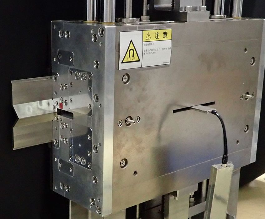
DC SEPTUM MAGNET BASED ON PERMANENT …                                  PHYS. REV. ACCEL. BEAMS 23, 012401 (2020)

FIG. 2. Movement of operating point on B-H curve under heat
cycle. While the operating point moves a–b–c for high Pc , it
moves a’–b’–c’ for low Pc, and an irreversible demagnetization
occurs.
                                                                 FIG. 4. Magnetic flux density (B) distribution at the central
                                                                 cross section in the beam direction.
Additional PMs are installed between the pole piece
and a septum plate for cancelling out the fringe field. In                            C. Septum plate
order to protect these magnets from demagnetization,
especially those close to the beam axis, each magnet                On the one hand, it is desirable to have the incident beam
piece is designed to be thick enough to have a large Pc .        and stored beam closer to each other, to reduce the field
Magnetic-shunt alloy plates for temperature compensa-            strength of a pulsed septum magnet in the downstream. On
tion and a movable shunt plate for varying the field             the other hand, the leakage field from the gap must be
strength are located close to side PMs. Pole pieces              sufficiently low to avoid any perturbations to the stored
                                                                 beam. As the dipole field is constant with time, an eddy
were made of pure iron and return yokes and plates were
                                                                 current, which can suppress the leakage field in case of a
JIS-SS400-specified steel [17].
   The simulated distributions of the magnetic flux              pulsed magnet, is not excited in the septum. Therefore,
density (B) the magnetic field (H) at the longitudinal center    the septum and the additional magnetic shield plates, if
of the magnetic circuit are shown in Fig. 4 and Fig. 5,          necessary, shield the magnetic field by their high magnetic
                                                                 permeabilities compared to the ambient air. A thin septum
respectively.
   With the B and H data, Pc was calculated from Eq. (1).
Figure 6 shows the distribution of Pc in PMs. The average
values of Pc in each PM are also shown in the figure.

                                                                 FIG. 5. Magnetic field (H) distribution at the central cross
      FIG. 3. Layout of magnetic circuit components.             section in the beam direction.

                                                           012401-3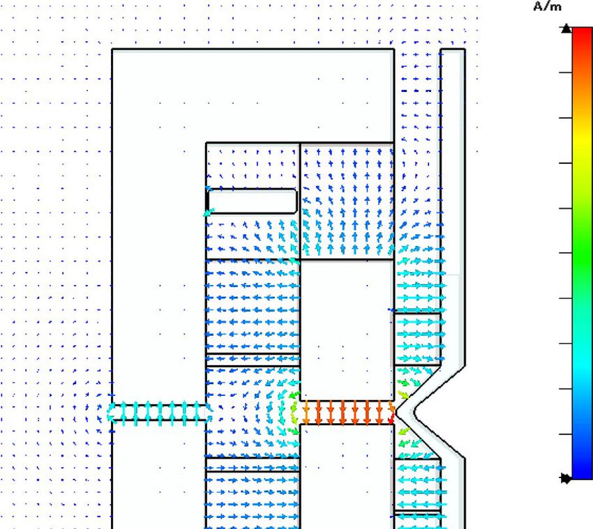
TSUTOMU TANIUCHI et al. PHYS. REV. ACCEL. BEAMS 23, 012401 (2020)
FIG. 6. Permeance coefficient (Pc ) distribution in PMs for the
shunt plate position (D) of 20 mm. hPc is are the average value
in PMs.
plate and a short distance between the septum plate and the
pole piece can bring closer the orbits of the incident and
stored beams. However, magnetic saturation in the septum
plate becomes higher and the leakage field from the septum
plate increases.
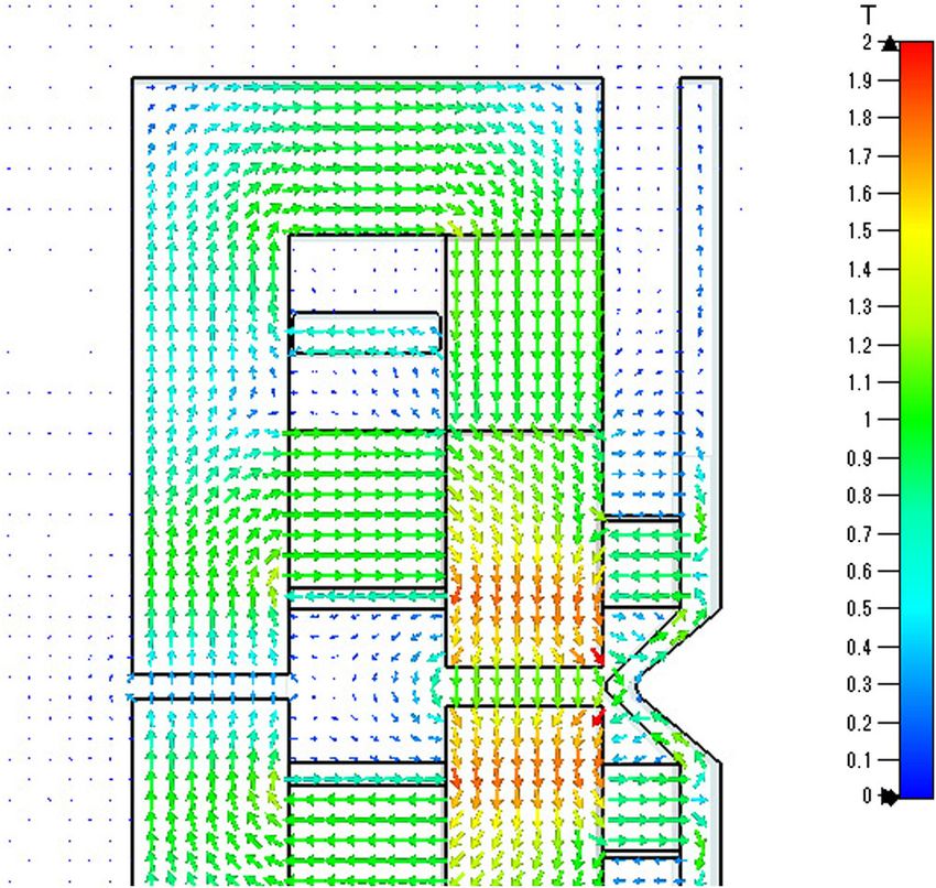
Therefore, we adopted a counter PM to cancel the FIG. 7. Fabricated PM-based septum magnet. Septum plates
magnetic flux in the septum plate. This made the plate are extended by 80 mm to the shield fringe field in the beam
thinner and we achieved the thickness of 7 mm on the direction.
median plane. Such a technique has been employed for
the end-field termination in undulator magnet arrays [18].
considering the compactness required by a dense injection
Furthermore, the septum plate was bent in a wedge-
section for SPring-8-II. Shunt plates can be moved verti-
shape to reduce the distance between the incident and
cally using rotating handles attached on top and bottom
stored beam orbits.
of the magnet. As the shunt plate gets closer to the PM,
The leakage field can be minimized by adjusting a
the magnetic flux in the plate increases and the gap-field
counter flux in the septum plate. Steel plates with a
strength decreases. Components of the bearing system were
thickness of 1 mm each were stacked near the counter
chosen to counter the magnetic force acting on the shunt
PM, to shunt the magnetic flux and adjust the counter flux.
plates shown in Fig. 8.
The thickness was adjusted to minimize the leakage field
The variable range of the gap field was designed to be
while measuring the magnetic field outside the septum
3% considering a fabrication error and recovery from time-
plate.
depending demagnetization.
The fringe field in the longitudinal direction, especially
at the pole end near the injection point, must also be cured.
The length of the septum plate was increased by 80 mm in E. Field monitoring slot
the longitudinal direction to shield the fringe field from the To guarantee the beam trajectory during actual machine
pole end, as can be seen in Fig. 7. operation, the magnetic field strength at the pole gap
must be monitored. Whereas, the gap field strength can
D. Variable-field mechanism be monitored indirectly by monitoring the excitation
In PM circuit manufacturing, it is rather difficult to current in the electromagnet, the magnetic field strength
optimize the gap field to a design value within a reasonable itself must be monitored using field measuring devices such
cost. One of the conventional ways is shimming. In our as a Hall sensor or a nuclear magnetic resonance (NMR)
case, the so-called outer plate mechanism was developed Teslameter. However, it is difficult to insert these sensors
for changing the gap field smoothly and quickly [12]. into the small gap of the septum magnet, which is occupied
However, as shown in Fig. 4, a shunt plates moving inside by the vacuum chamber, and widening the pole pieces leads
the return yoke was adopted to the septum magnet to an increase in the PMs weight and cost. Instead, we
012401-4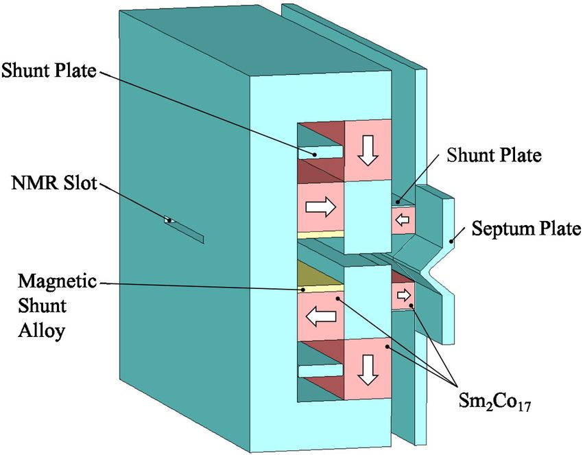
DC SEPTUM MAGNET BASED ON PERMANENT …                                     PHYS. REV. ACCEL. BEAMS 23, 012401 (2020)

                                                                    FIG. 10. Field monitoring slot at the return-yoke and inserted
                                                                    NMR probe.
FIG. 8. Simulated magnetic forces acting on a tuning shunt
plate as a function of the shunt plate position (D), where Fx and   temperature coefficient (10−7 =°C), and resistance to radi-
Fy are the horizontal and vertical components, respectively. (The   ation compared to Hall sensors. The dimensions of the field
coordinate system is shown in Fig. 6). The movable range of the     detecting volume in the NMR probe are designed to be
plate in the fabricated septum magnet is 13–40 mm.
                                                                    5 mm (H) ×15 mm (W) ×5 mm (D) for installing in a slot
                                                                    of height 6 mm. In this volume, a field uniformity of 10−4
adopted a slot in the return yoke to monitor the field              is required to obtain a good signal level for the NMR
strength correlated to one at the pole gap. Figure 9 shows          waveform. Figure 10 shows the NMR probe installed in the
the correlation between field strengths at the pole gap and         monitoring slot.
the return-yoke slot (NMR slot). The field strength in the
NMR slot depends on the magnetic saturation of the yoke
near that slot. We chose a proper thickness of the return                F. Compensation for temperature dependence
yoke and a slot size to induce a sufficient magnetic field             The temperature coefficient (Tc ) of Sm2 Co17 is typically
strength into the slot.                                             −0.04%=°C. Although it is smaller than that of Nd-Fe-B,
   The NMR Teslameter was chosen for the field moni-                which is typically −0.1%=°C, it may not be negligible for a
toring owing to its higher resolution (< 10−6 ), lower              stable beam operation. We have demonstrated that the
                                                                    temperature dependence of the gap field strength in PM-
                                                                    based dipoles can be reduced sufficiently using an Fe-Ni
                                                                    alloy (magnetic-shunt alloy) [12]. The same technique was
                                                                    applied for this septum magnet. We set the target range of
                                                                    the temperature coefficient to 5 × 10−5 =°C. The mag-
                                                                    netic-shunt alloy used as a temperature compensator was
                                                                    MS-2 [19], in which the composition ratio of Ni was 31%
                                                                    and the linearity of temperature dependence was optimized
                                                                    for the temperature range from 20 to 40 °C.
                                                                       We measured the B-H curve of the alloy at magnetic
                                                                    fields of up to 80 kA=m. Using these data in the simulation,
                                                                    a necessary amount of MS-2 was estimated to minimize
                                                                    the Tc . The magnetic-shunt alloy was rolled into 1-mm-
                                                                    thick plates, which were stacked near the PMs. The total
                                                                    thickness of MS-2 was adjusted while measuring the Tc by
                                                                    using an NMR Teslameter (Echo-Denshi KK) in a temper-
                                                                    ature-controlled booth. Figure 11 shows the history of the
                                                                    MS-2 thickness optimization. The optimal thickness was
FIG. 9. Correlation between field strengths at the pole gap and     5.5 mm; an alloy plate was cut in half to be equivalent to
return-yoke slot.                                                   the thickness of 0.5 mm. The temperature dependence at a

                                                              012401-5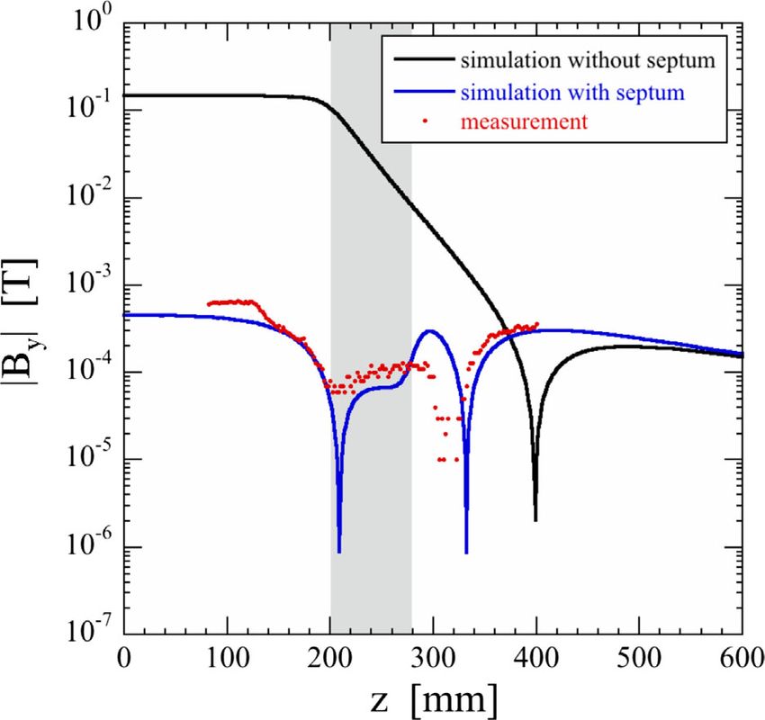
TSUTOMU TANIUCHI et al.                                                 PHYS. REV. ACCEL. BEAMS 23, 012401 (2020)

                                                                  The typical demagnetization at a PM surface after the
                                                                  baking was 0.5–1%.
                                                                     The septum magnet was assembled in a booth to
                                                                  prevent contamination from magnetic dust. The strong
                                                                  magnetic field zone was specified by the booth for safety.
                                                                  A device to alert against strong magnetic fields was worn
                                                                  by workers in the booth to prevent unintended exposure to
                                                                  the strong field.
                                                                     To overcome the strong magnetic force, the PMs using
                                                                  an assembly jig were introduced into iron yokes. The gap
                                                                  distance was required to be precisely aligned to ensure a
                                                                  good field region. We adopted nonmagnetic side frames
                                                                  made of aluminum to position the pole pieces within a
                                                                  required tolerance and support them against the attractive
                                                                  magnetic force, and installed them at both ends of the
                                                                  pole pieces.
FIG. 11. Temperature coefficient minimization through opti-
                                                                       III. MAGNETIC FIELD MEASUREMENT
mization of magnetic-shunt alloy (MS-2) thickness.
                                                                                A. Gap-field variable range
thickness of 5.5 mm is shown in Fig. 12. Tc was expected             As described in preceding section, the gap field strength
to be sufficiently small around an atmospheric temperature        can be varied by moving the shunt plates inside the return
of 27° C in the accelerator tunnel at SPring-8.                   yoke. Figure 13 shows the dependence of the measured
                                                                  gap-field strength on the upper and lower shunt plate
                                                                  positions. In this case, the lower plate was moved from
                      G. Fabrication                              D ¼ 13 to 40 mm while the upper plate was fixed at
   The fabrication process of the septum magnet consists          D ¼ 13 mm; then, the upper plate was moved from D ¼ 13
of PM block production, iron yoke, frame fabrication, and         to 40 mm while the lower plate was fixed at D ¼ 40 mm.
assembly.                                                         The variable range of approximately 2% is obtained by
   In PM block production, basic PM pieces were sintered          moving one of the upper or lower plates, and in total, a
and shaped. They were then, using a heat-resistant adhe-          variable range of 3.9% is ensured by moving the both
sive, bonded to form PM blocks for the magnetization. In          plates.
order to reduce the initial time-dependent demagnetization,          When the upper and lower plates are in asymmetrical
the PM blocks were baked [20] at a temperature of 200 °C.         positions, the magnetic field distribution in the gap may be
                                                                  slightly deformed. According to our numerical simulation

FIG. 12. Temperature dependence of gap field after MS-2
thickness optimization. The value of Tc was obtained by fitting   FIG. 13. Gap-field strength variation measured by moving the
data in the range of 26–28 °C.                                    lower and upper shunt plates.

                                                            012401-6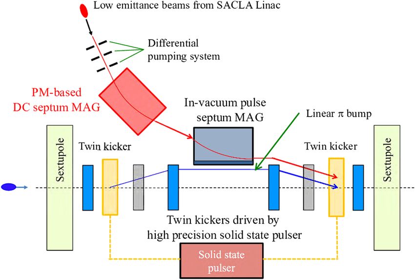
DC SEPTUM MAGNET BASED ON PERMANENT …                                    PHYS. REV. ACCEL. BEAMS 23, 012401 (2020)

for Fig. 13, the dipole field is deformed in the vertical axis
by dBy =dy ¼ 0.2 T=m when one of the shunt plates is in
the position of D ¼ 13 mm while the other is D ¼ 40 mm.
No significant deformation in the horizontal axis, dBy =dx,
is found. When the asymmetry needs to be avoided, one
may set the same positions D for both the plates while
keeping the total variable range, 3.9%.

                      B. Leakage field
   After the temperature-dependence compensation and
adjustment of fringe field cancellation, three-dimensional
magnetic field measurement was performed with a temper-
ature compensated Hall probe, (three-axis probe MMZ-
2508-UH, three-channel Hall effect gaussmeter Model 460,
Lake Shore Cryotronics, Inc.).
   Figure 14 shows the transverse distribution of magnetic
flux density, By , at the longitudinal center. The simulated
fringe field without a septum (black in Fig. 14) shows no          FIG. 15. Longitudinal distribution of magnetic flux density at
significant reduction compared with the gap field (1.2 T),         x ¼ 47 mm. Black and blue lines represent the simulated dis-
while that with a septum (blue) is suppressed to below             tribution without and with the septum plate, respectively. Red
10−3 T. The measured fringe field with the septum is               dots represent the measured data with the septum plate.
consistent with that expected by the simulation. The
residual leakage field can be shielded below the geo-                 In the longitudinal direction, the field strength is also
magnetic intensity by surrounding the beam chamber with            significantly suppressed, as shown in Fig. 15, and again the
a mu metal sheet. We assume the distance between the               measured field with the septum is well suppressed as
incident beam and the septum plate is 15 mm. The stored            designed using the simulation.
beam on the bump orbit can be nearly 30 mm from the
incident beam at the downstream end of the dc septum.
                                                                        IV. REDUCTION IN SEPTUM THICKNESS
                                                                      Aiming at further reduction of the injection amplitude for
                                                                   the future, we here discuss a possibility of reducing the
                                                                   septum thickness even further. One of the solutions is the
                                                                   multilayering of the septum plate. The advantage of using
                                                                   multilayer shielding is well known [21].
                                                                      We employed a double-septum structure with a non-
                                                                   magnetic gap in between as shown in Fig. 16. As an
                                                                   example, an aluminum plate can work as the nonmagnetic
                                                                   gap. In Fig. 16, the thickness of the septum plate on the
                                                                   injection beam side (left in Fig. 16) has a thickness of

FIG. 14. Transverse distribution of magnetic flux density at the
longitudinal center (z ¼ 0 mm) of the dc septum. Black and blue
lines represent the simulated distribution without and with the    FIG. 16. Comparison between single- and double-septum
septum plate, respectively. Red dots represent the measured data   structures. (Left) Original shape with the thickness of 7 mm at
with the septum plate. The origin of horizontal axis is defined    the median plane. (Right) Double layer of the iron with non-
at the incident beam position. The septum plate occupies the       magnetic gap between them. The thickness is reduced by 2.2 mm
position between x ¼ 15 and 22 mm.                                 compared to the original shape.

                                                             012401-7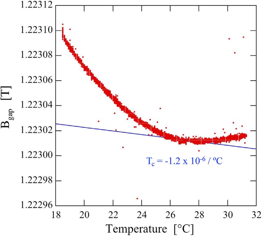
TSUTOMU TANIUCHI et al.                                                   PHYS. REV. ACCEL. BEAMS 23, 012401 (2020)

                                                                    prevention, etc. Future developments based on this study
                                                                    are expected not only to help accelerators reduce their
                                                                    power consumption, but also engender new possibilities for
                                                                    choosing even higher packing factor lattices and other
                                                                    challenging accelerator designs with ease.

                                                                                     ACKNOWLEDGMENTS
                                                                       This work was supported by JST Next Generation
                                                                    Accelerator Technology Development Program and the
                                                                    RIKEN SPring-8 Center (RSC). The authors would like to
                                                                    thank H. Tanaka for directing the development program of
                                                                    the PM-based septum magnet. One of the authors (T. W.)
                                                                    would like to acknowledge J. Chavanne for overall dis-
                                                                    cussion on magnets.

FIG. 17. Transverse distribution of magnetic flux density at the
                                                                     [1] H. Tanaka, T. Ishikawa, S. Goto, S. Takano, T.
longitudinal center (z ¼ 0 mm) of the dc septum. Blue line
                                                                         Watanabe, and M. Yabashi, SPring-8 upgrade project, in
represents the simulated distribution for the original 7-mm-thick
                                                                         Proceedings of the 7th International Particle Accelerator
mono layer and red line represents that for 4.8-mm-thick double
                                                                         Conference, Busan, Korea, 2016 (JACoW, Geneva, 2016),
layer septum.
                                                                         pp. 2867–2870.
                                                                     [2] P. Raimondi, ESRF-EBS: The extremely brilliance source
2.2 mm, while that on the stored beam is 1.4 mm. The gap                 project, Synchrotron Radiat. News 29, 8 (2016).
in between is 1.2 mm, so that the overall septum thickness           [3] L. Liu, F. H. de Sá, and X. R. Resende, A new optics
is 4.8 mm, which is as much as 2.2 mm thinner than the                   for sirius, in Proceedings of the 7th International Particle
                                                                         Accelerator Conference, Busan, Korea, 2016 (JACoW,
original case of the single-septum structure. The transverse
                                                                         Geneva, 2016), pp. 3413–3416.
distribution of magnetic flux density at the longitudinal            [4] H. D. Glass, B. C. Brown, G. W. Foster, W. B. Fowler, J. E.
center (z ¼ 0 mm) of the dc septum is plotted in Fig. 17.                Haggard, D. J. Harding, G. P. Jackson, M. P. May, T. H.
Thus, it is verified that the double-septum structure enables            Nicol, J. F. Ostiguy, P. Schlabach, G. A. Smith, and
us to significantly reduce the septum thickness while                    J. T. Volk, Permanent dipole magnets for the 8 GeV
keeping the same level of the leakage field. The thickness               transfer line at FNAL, in Proceedings of the Particle
will be reduced by the increase in a number of layers even               Accelerator Conference, Vancouver, BC, Canada, 1997
further as far as it is reasonably feasible in practical                 (IEEE, New York, 1997), Conf 97-3257.
fabrications of the magnet.                                          [5] Y. Iwashita, Y. Tajima, M. Ichikawa, S. Nakamura, T. Ino,
                                                                         S. Muto, and H. M. Shimizu, Variable permanent magnet
                                                                         sextupole lens for focusing of pulsed cold neutrons, Nucl.
                     V. CONCLUSION                                       Instrum. Methods Phys. Res., Sect. A 586, 73 (2008).
   A PM-based septum magnet was developed for the                    [6] Y. Iwashita, M. Yamada, S. Ushijima, Y. Fuwa, Y. Nasu, H.
                                                                         Tongu, M. Masuzawa, and H. M. Shimizu, Variable per-
injection section of next-generation light sources. The fringe           manent magnet multipoles, IEEE Trans. Appl. Supercond.
magnetic field on the orbit of the stored beam was shielded              22, 4000905 (2012).
by a 7-mm thick septum plate with counter-field PMs. The             [7] C. Benabderrahmane, J. C. Biasci, J. F. Bouteille, J.
gap field strength can be varied by displacing the shunt plate.          Chavanne, L. Eybert, L. Goirand, G. Le Bec, L. Lefebvre,
Issues unique to a PM, such as temperature characteristic and            S. M. Luizzo, D. Martin, C. Penel, P. Raimondi, J. L.
demagnetization, were also solved. Furthermore, we numeri-               Revol, F. Villar, and S. White, Status of the ESRF-EBS
cally demonstrated that the septum thickness can be reduced              magnets, in Proceedings of the 9th International Particle
further by multilayering the septum plate. In our case, the              Accelerator Conference, Vancouver, BC, Canada, 2018
overall thickness was reduced by 2.2 mm with the double-                 (JACoW, Geneva, 2018), pp. 2648–2651.
septum structure.                                                    [8] P. N’gotta, G. Le Bec, and J. Chavanne, Hybrid high
                                                                         gradient permanent magnet quadrupole, Phys. Rev. Accel.
   The permanent magnet has drawn attention as a viable
                                                                         Beams 19, 122401 (2016).
candidate in the development of next-generation light                [9] J. Citadini, L. N. P. Vilela, R. Basilio, and M. Potye, Sirius-
sources and related fields. It is reasonable to fabricate                details of the new 3.2 T permanent magnet superbend,
injection dc magnets, which normally consume large                       IEEE Trans. Appl. Supercond. 28, 4101104 (2018).
amounts of power, using permanent magnets, in regards               [10] Y. Iwashita and A. Noda, Massless septum with hybrid
to power consumption reduction, power supply failure                     magnet, in Proceedings of 6th European Particle

                                                              012401-8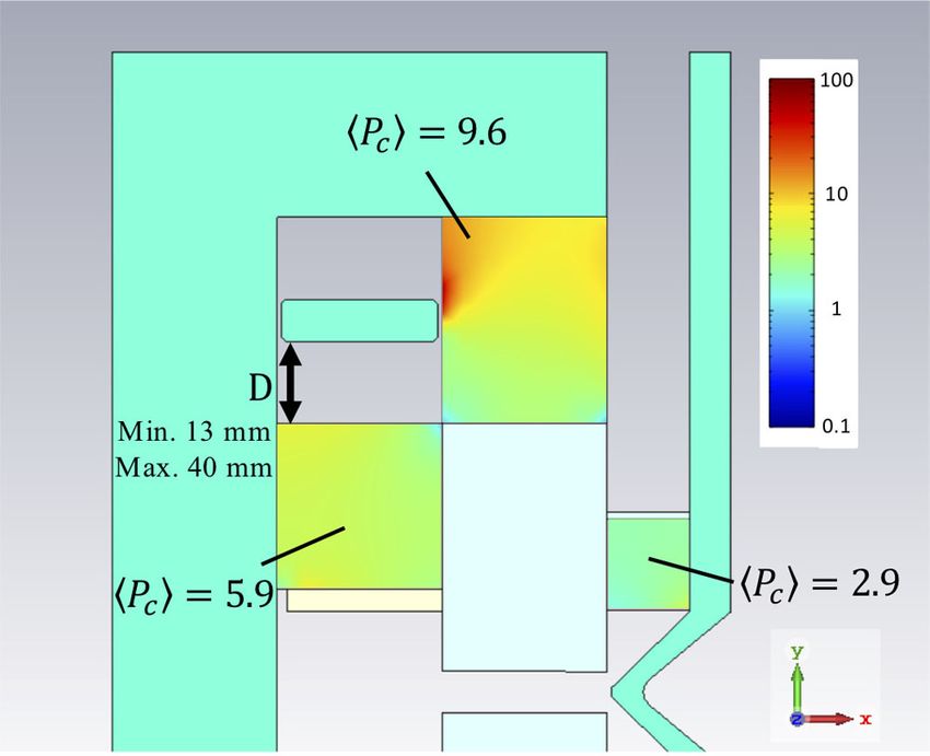
DC SEPTUM MAGNET BASED ON PERMANENT …                                     PHYS. REV. ACCEL. BEAMS 23, 012401 (2020)

       Accelerator Conference, Stockholm, Sweden, 1998 (IOP,        [15] T. Bizen, R. Kinjo, T. Hasegawa, A. Kagamihata, Y. Kida,
       London, 1998), pp. 2109–2110.                                     T. Seike, T. Watanabe, T. Hara, T. Itoga, Y. Asano, and T.
[11]   T. Kawakubo, E. Nakamura, M. Numajiri, M. Aoki, T.                Tanaka, Radiation-induced magnetization reversal causing
       Hisamura, and E. Sugiyama, Permanent magnet generating            a large flux loss in undulator permanent magnets, Sci. Rep.
       high and variable septum magnetic field and its deterio-          6, 37937 (2016).
       ration by radiation, in Proceedings of 9th European          [16] Dassault Systèmes, CST Studio Suite, https://www.3ds
       Particle Accelerator Conference, Lucerne, Switzerland,            .com/products-services/simulia/products/cst-studio-suite/.
       2004 (EPS-AG, Lucerne, 2004), pp. 1696–1698 [http://         [17] Japanese Industrial Standards, JIS G 3101, Rolled steels
       accelconf.web.cern.ch/AccelConf/e04/].                            for general structure.
[12]   T. Watanabe, T. Taniuchi, S. Takano, T. Aoki, and K.         [18] J. Chavanne, P. Elleaume, and P. V. Vaerenbergh, The
       Fukami, Permanent magnet based dipole magnets for next            ESRF insertion devices, J. Synchrotron Radiat. 5, 196
       generation light sources, Phys. Rev. Accel. Beams 20,             (1998).
       072401 (2017).                                               [19] Hitachi Metals Neomaterial, Ltd., MS-2, http://www
[13]   S. Takano, K. Fukami, C. Kondo, M. Masaki, M. Oishi, M.           .hitachi-metals-neomaterial.co.jp/english/product/liv/08
       Shoji, K. Tamura, T. Taniuchi, K. Yanagida, T. Watanabe,          .html.
       K. Hamato, J. Kataoka, K. Kusano, K. Ogata, Y. Saito,        [20] T. Bizen, Y. Asano, T. Hara, X. Marechal, T. Seike, T.
       H. Akikawa, and K. Sato, Renovation of off-axis beam              Tanaka, H. S. Lee, D. E. Kim, C. W. Chung, and H.
       injection scheme for next-generation photon sources, in           Kitamura, Baking effect for NdFeB magnets against
       Proceedings of the 10th International Particle Accelerator        demagnetization induced by high-energy electrons, Nucl.
       Conference, Melbourne, Australia, 2019 (JACoW, Geneva,            Instrum. Methods Phys. Res., Sect. A 574, 401 (2007).
       2019), pp. 2318–2321.                                        [21] T. J. Sumner, J. M. Pendlebury, and K. F. Smith,
[14]   TOKIN Corporation, LM-32SH, https://www.tokin.com/                Conventional magnetic shielding, J. Phys. D 20, 1095
       english/product/pdf_dl/permanentmagnets.pdf.                      (1987).

                                                              012401-9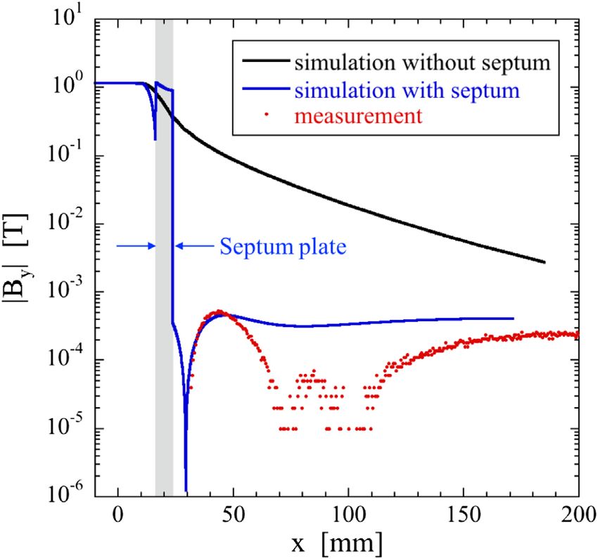
You can also read