HERMES: revisions in the design for a high-resolution multi-element spectrograph for the AAT
←
→
Page content transcription
If your browser does not render page correctly, please read the page content below
HERMES: revisions in the design for a high-resolution multi-element
                       spectrograph for the AAT
    Samuel C. Barden a, Damien J. Jonesb, Stuart I. Barnesc, Jeroen Heijmansa, Anthony Henga, Greg
                         ∗

Knightd, David R. Orra, Greg A. Smitha, Vladimir Churilova, Jurek Brzeskia, Lewis G. Wallera, Keith
      Shortridgea, Anthony J. Hortona, Don Mayfielda, Roger Haynese, Dionne M. Haynese, Denis
     Whittarda, Michael Goodwina, Scott Smedleya, Ian Saundersa, Peter R. Gillinghama, Ed Pennya,
    Tony J. Farrella, Minh Vuonga, Ron Healda, Steve Leea, Rolf Mullera, Ken Freemanf, Joss Bland-
                              Hawthorng, Daniel F. Zuckera, Gayandhi De Silvaa
              a
                Anglo-Australian Observatory, PO Box 296, Epping NSW 1710, Australia;
                     b
                       Prime Optics, 17 Crescent Road, Eumundi, QLD 4562, Australia;
  c
    Department of Physics and Astronomy, University of Canterbury, Private Bag 4800, Christchurch
                                             8140, New Zealand
                d
                  Sinclair Knight Merz, 100 Christie Street, Sydney NSW 2065, Australia;
                             e
                               innoFSPEC - Astrophysikalisches institut Potsdam
                                An der Sternwarte 16, 14482 Potsdam, Germany
f
  Research School of Astronomy & Astrophysics, Mount Stromlo Observatory, Cotter Road, Weston
                                            ACT 2611, Australia;
                       g
                         A28 – Physics, The University of Sydney NSW 2006, Australia

                                                      ABSTRACT

The AAO is building an optical high resolution multi-object spectrograph for the AAT for Galactic Archaeology. The
instrument has undergone significant design revision over that presented at the 2008 Marseilles SPIE meeting. The
current design is a 4-channel VPH-grating based spectrograph providing a nominal spectral resolving power of 28,000
and a high-resolution mode of 45,000 with the use of a slit mask. The total spectral coverage is about 1000 Angstroms
for up to 392 simultaneous targets within the 2 degree field of view. Major challenges in the design include the
mechanical stability, grating and dichroic efficiencies, and fibre slit relay implementation. An overview of the current
design and discussion of these challenges is presented.

Keywords: spectrograph, high resolution, volume phase holographic grating, multi-object, AAT, galactic archeology,
   fibre

                                                  1. INTRODUCTION

A new facility class instrument for the Anglo-Australian Telescope (AAT) is currently in development at the Anglo-
Australian Observatory (AAO). This instrument, High Efficiency and Resolution Multi-Element Spectrograph
(HERMES), is an optical high-resolution multi-object spectrograph designed primarily for a major survey of ~1 million
stars in the Milky Way galaxy to perform “Galactic Archaeology” to unravel the formation history of the Galaxy. The
instrument, to be fed with the existing 2dF robotic fibre positioning system, has undergone significant design revision
over that presented at the 2008 Marseilles SPIE meeting. HERMES has past the conceptual design review in February
2010, The current design is a 4-channel VPH-grating based spectrograph providing a spectral resolving power of 28,000
standard and a high resolution mode ranging between 40,000 to 50,000 with a slit mask. The total spectral coverage is
about 1000 Angstroms for up to 392 simultaneous targets within the 2 degree field of view. The collimator is an f/6.32
off-axis Houghton derivative delivering a 190 mm diameter pupil on the gratings. The entrance slit is a curved array of
the fibres that compensates for high order dispersion terms to straighten out the slit curvature on the detector. The output

∗
    scb@aao.gov.au; phone +61 2 9372 4852; fax +61 2 9372 4880; aao.gov.au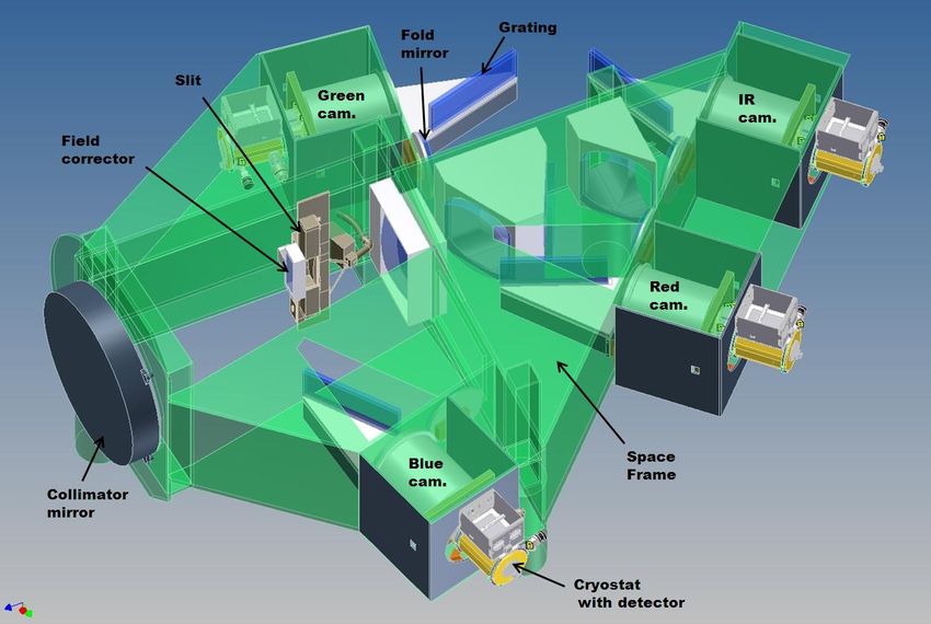
of the fibres are relayed from f/3.15 to f/6.32 with micro-optic relays. Dichroic beam splitters are used to split the light
into the four channels. Each channel utilizes fold mirrors, exchangeable VPH gratings, all transmissive camera optics,
and a 4k by 4k E2V detector system optimized for the wavelength band of each channel. All surfaces are either spherical
or plano except for the first surface of each camera, which is paraboloid. Major challenges in the design include the
mechanical stability, grating and dichroic efficiencies, and fibre slit relay implementation. An overview of the current
design and discussion of these challenges is presented.

                                               2. SCIENCE OBJECTIVES

HERMES provides an extraordinary and unprecedented opportunity to undertake a million-star archaeological survey of
the Galactic stellar disk. This multi-year Galactic Archaeology (GA) observational program will obtain detailed
elemental abundances and precise radial velocities for each targeted star. Elemental abundances representing the main
nucleogenesis processes in both dwarf and giant stars will allow chemical tagging of the individual stars to their original
formation event, and accurate velocities will permit differentiation of stars by their dynamics. The resulting data sets will
yield a comprehensive view of the formation and evolution of the Galactic disk, enabling the reconstruction of the
original stellar building blocks of the Galactic disk and address the following basic questions:

    •    What were the conditions of star formation during early stages of Galaxy assembly?
    •    When, where and what drove the major episodes of star formation is the disk?
    •    To what extent is the Galactic disk composed of stars from merger events?
    •    Under what conditions, and in what types of systems did the accreted stars form?
    •    How have the stars that formed in situ in the Disk evolved dynamically since their birth?
    •    Where are the solar siblings that formed together with our Sun?

HERMES will also present a tremendous opportunity for scientific synergies with the European Space Agency’s GAIA
mission. GAIA, a €500 million astrometric satellite scheduled for launch by 2012, will measure precise distances and
tangential motions for the majority of HERMES GA survey stars. Precise distances from GAIA will yield accurate ages
for a significant fraction of those stars, which will allow direct determination of the evolution of elemental abundances
with time in the disk of the Milky Way, as well as providing critical information for studies of stellar astrophysics
Transverse velocities, in conjunction with the radial velocities measured by HERMES, will give a complete picture of
the space motion for each star, and hence identify spatially-mixed stars with a common origin through their similar
dynamics. The combination of HERMES abundances and radial velocities along with GAIA astrometry will provide a
truly extraordinary legacy for unravelling the history of the galaxy.

In addition to the GA objectives, HERMES will be a powerful instrument for the study of stellar astrophysics, the
interstellar medium, and the magellanic clouds. Table 1 provides a summary of the observational requirements for each
of the different science cases envisioned for the HERMES instrument.

    Table 1. Summary of observational requirements for HERMES science.
Requirement             Galactic                 Stellar                 Interstellar             Radial Velocity
                        Archaeology              Astrophysics            Medium                   Variability
Brightness of           10−14 for main GA        Typically brighter      Wide range; not          Typically brighter
Targets (V mag)         survey; down to 16 –     than 14                 strictly relevant for    than 14
                        17 for targeted                                  emission-line objects
                        observations
Wavelength              4708Å – 4893Å            Wide range; in some     Wide range across        Wide range; if using
Windows (Å)             5649Å – 5873Å            cases GA                optical spectrum         iodine cell, 4800Å –
                        6481Å – 6739Å            wavelength windows                               6000Å
                        7590A – 7890Å            appropriate
Spectral Resolution     ~30,000                  ~30,000;                ~30,000;                 ~50,000
(λ/Δλ)                                           ~50,000                 ~50,000
Sensitivity (SNR)       100 at V~14 in 1         Wide range              Wide range               Wide range
                        hour (GA survey)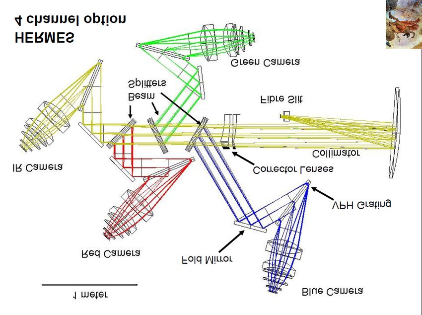
3. OPTICAL AND MECHANICAL DESIGN

1. Optical Design
The initial concept for HERMES was based upon a white pupil echelle configuration that made use of the existing
AAOmega hardware [X]. The design was significantly altered when it was decided to make HERMES a separate
standalone instrument in order to minimize the downtime impact on AAOmega. A subsequent cost tradeoff study
revealed that a multi-channel instrument utilizing first order volume-phase holographic (VPH) gratings was preferable
over the white pupil echelle design. A four-channel instrument design was developed providing nearly 1000 Å of total
spectral coverage for optimal wavelength coverage for the GA survey and flexible reconfiguration (by exchanging
gratings) required for the alternative scientific objectives. Fig 1 shows the optical design and the coordinate reference
frame.

     Fig 1. Optical schematic of the HERMES spectrograph looking down with spectral dispersion in the plane of the figure.
         The bottom figure shows the global reference frame with the x-axis pointing into the plane of the figure.

The primary design characteristics are listed here.

    •    2 degree field of view (2dF facility)
    •    Two 392 fibre slits (one for each 2dF field plate)
    •    Fixed configuration (no camera articulation or grating rotation)
    •    Curved slit to compensate for wavelength curvature from the grating
    •    Off-axis f/6.3 collimator, modified Houghton design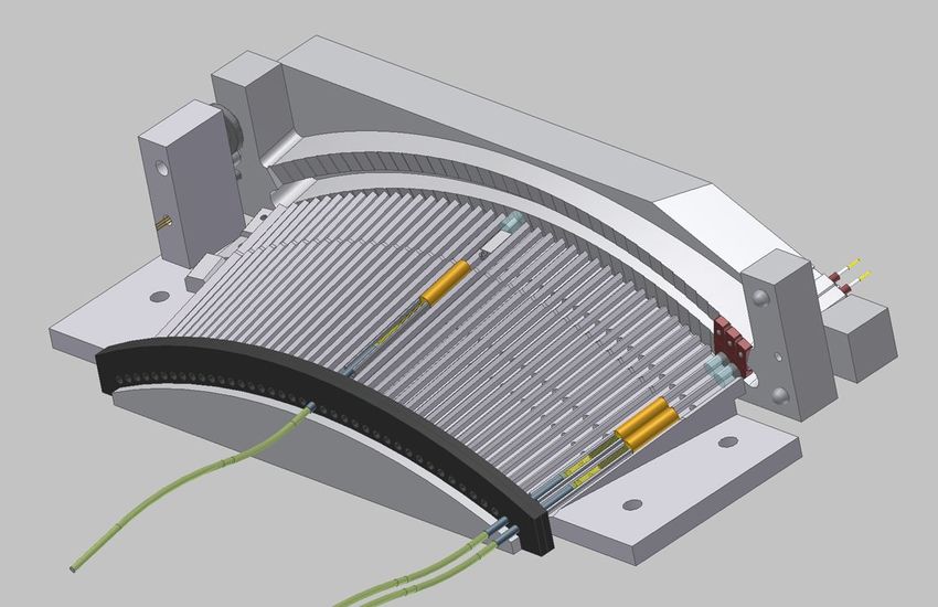
•   190 mm beam diameter
    •   R2.5 (68°) VPH gratings
    •   Exchangeable gratings and beam splitters
    •   4 channels
    •   3 dichroic beam splitters
    •   f/1.7 cameras
    •   All spherical optics except for front surface of each camera
    •   Front surface of each camera is a paraboloidal surface
    •   Red and IR cameras are identical
    •   4k by 4k pixel detectors (E2V)
    •   15 micron pixels
    •   ~4 pixel sampling at R~28,000
    •   Optional slit mask for R~45,000
    •   Optional Iodine absorption cell

The wavelength bands for the GA science and the usable wavelength bands for each channel are shown in Fig 3.
Changing wavelengths from the GA bands requires a different grating, possibly a different beam splitter, and a refocus of
the cameras (piston and tilt).

    Fig 3. Wavelength bands for the HERMES channels and GA spectral windows.

2. HERMES System
Fig 5 shows the system and interface structure for HERMES. Details on the following components will be discussed in
the remainder of this paper.

    •   Fibre cable and slit assembly
    •   Beam splitters
    •   VPH gratings
    •   Cameras and detectors
    •   Space frame and cryostat
    •   Grating ghosts
    •   Efficiency model
    •   Data simulation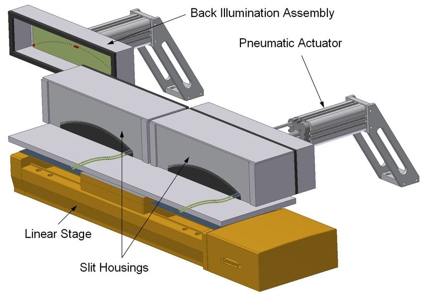
Fig 5. System diagram for HERMES.

3. Fibre Cable and Slit Assembly
The 2dF facility has two field plates. While one is in the observing position the other is aligned with the robotic
positioner for reconfiguration for the next target field. A tumbler swaps the two plates in between target field
observations. 400 fibre positions are available around the circumference of each of the two 2dF field plates. Eight of
these positions are utilized by fibre guide probes that feed to a guide TV. The remaining 392 positions are for science
targets and sky observations. The science fibres will run a length of about 40 metres to the HERMES spectrograph in 40
groups of 10 fibres for each field plate. The fibres have a 140µm core diameter and a 198µm outer diameter including
the cladding and buffer. Each science fibre probe in 2dF will contain two fibres: one for AAOmega and one for
HERMES. The robotic positioner software will configure the probe according to which instrument is in use. The full
fibre cable will house a minimum of 1568 fibres (two sets of 392 fibres to both AAOmega and HERMES) plus spares.
Consideration is underway to add back the eight missing fibres from each field plate with fibres that are linked to a
calibration source for simultaneous wavelength calibration.
Exploration was made for implementing a fibre connector rather than having two fibres in the 2dF science probes. The
dual fibre probe approach was selected after cost and feasibility comparisons with the connector showed the dual
approach to be less risky and more cost beneficial.

In HERMES, the slit must be curved in order for the detector to see the same wavelength coverage for all fibre apertures.
This is due to second order terms in the dispersion from the grating due to out of plane illumination. Fig 7 shows the
geometrical arrangement for the fibre slit. The axis of the fibres are aligned such that the pupils all overlap at the
grating.

    Fig 7. Geometrical configuration of the fibre slit. Upper left is view looking at slit end from collimator along axis of
         symmetry. Upper right is side view. Lower right is top view.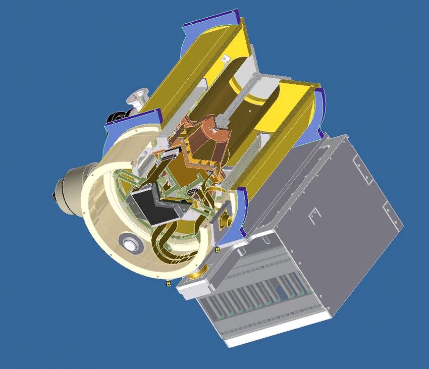
A lens relay is required in the slit to relay the f/3.15 output of the fibres to the f/6.3 focal ratio of the collimator. This
relay allows the collimator to be off-axis so that mechanical components of the curved slit unit do not interfere with the
light path. Fig 9 displays the optical schematic of the relay optics and the mechanical concept for the slit unit.
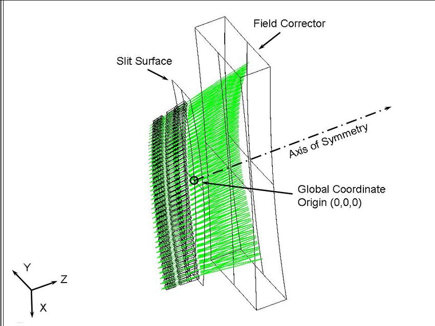
Fig 9. Top figure shows the optical relay. The bottom two show the mechanical concept for the assembly of the slit and
         relay optics and translation mechanism to move the slits between the back illumination systems.
When the field plate is reconfiguredthe fibres must be back-illuminated so that the robotic positioner can measure the
fibre positions. Back illumination ports are required to provide such illumination. Fig 9 (lower image) and Fig 11 show
the way in which the slits will be alternated between the observing position and the back illumination ports.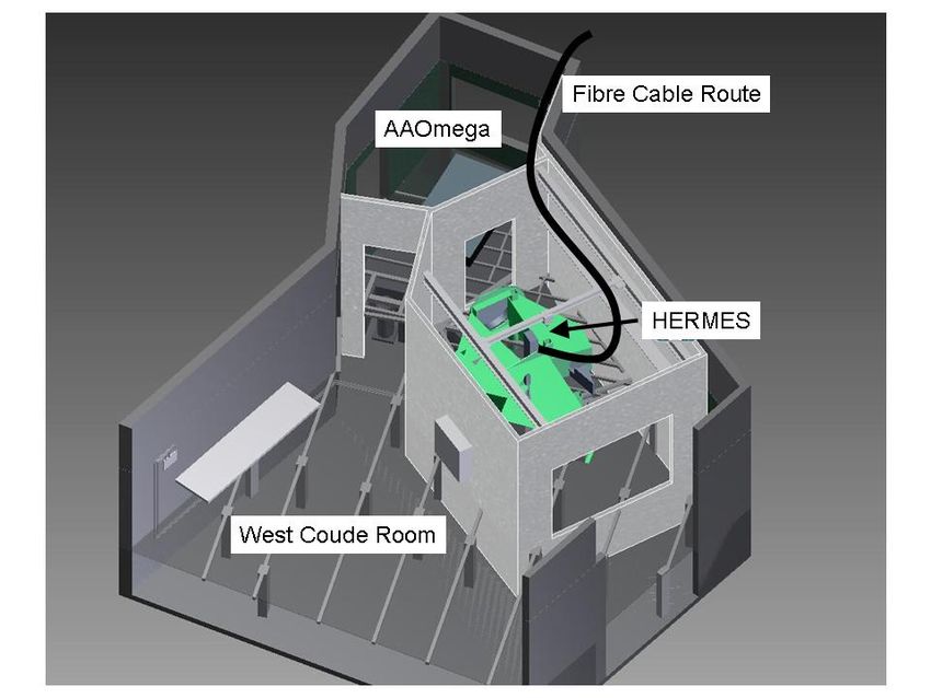
Fig 11. Schematic of the two positions for the HERMES slits.
For the higher resolution mode, a custom slit mask will be fabricated for both slit assemblies and mounted at the slit
image formed by the relay optics. Fig 13 shows the dimensions and orientation of the slit apertures on the mask
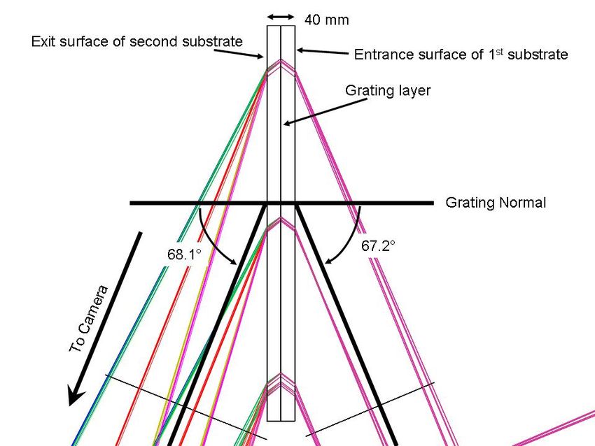
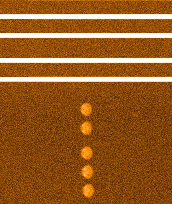
Fig 13. Slit mask apertures for 20 of the 400 fibres.
The resolution can be increased by decreasing the image width in the spectral direction down to 2.5 pixels using a slit
mask. The analyses on the resulting image quality are shown in Figure 15 for wavelengths ranging 581-587nm. The
complete optical model is taken into account. The pixelated resolution for these fibres is calculated to be 52-54,000. β
and µ are parameters to match the full width at half maximum (FWHM) and mean of a Gaussian profile fit. This model
can be optimized to the actual profile shape.

Figure 15 Fibre spectral image profile width on the detector (β in pixels); pixelated fibre image profile (black
line), Gaussian profile fit to fibre image profile to calculate resolution, R*10^3,(red line).

4. Beam splitters
The design for the Blue and Green channel beam splitters is not particularly challenging except for the size of the
elements required. The footprint of light on the Blue beam splitter is 280 by 530 mm. It was decided to make all beam
splitters the same size so to minimize design effort. The illumination angles for the Blue and Green beam splitters are
30°. The illumination angle for the Red beam splitter must be 45° in order to fit in the Red channel. The high angle on
the Red beam splitter increases the complexity of the dichroic design for performance in unpolarized light. Fig 17 shows
the sizing of the beam splitters and the footprint of light as it progresses through the chain into the IR channel. Fig 19
displays the polarization issue with the Red beam splitter. Fortunately, the GA requirements provide a wide gap between
the Red and IR channels. Shifting the wavelength transition blueward would provide adequate unpolarized performance
for the GA case.

The requirement that HERMES have four channels of spectral coverage in order to meet the wavelength demands of the
GA survey imposes a tight geometrical constraint on the Blue and Red channels (see Fig 1). The grating of the Red
channel comes very close to the beam propogating off the Blue beam splitter. The 45°on the Red beam splitter is
required to keep the Red channel from obstruction the Blue channel light With a straight slit, there would have been two
geometrical solutions for each channel, however, the presence of the curved slit eliminates that symmetry resulting in a
constrained geometrical layout.

    Fig 17. Side view of light path through beam splitters. The pupil from all fibres overlap on the grating.
Fig 19. Polarization issue with Red beam splitter at the use angle of 45°. The p-polarization transitions at a significantly
bluer wavelength than the s-polarization. (Plot provided by D. Baker, Optical Coatings Associates Pty Ltd,
Queensland, Australia)
5. VPH gratings
Volume phase holographic (VPH) gratings will be used to disperse the light. The gratings will be operated in the Littrow
condition. In order to match the spectral coverage to the detectors while achieving adequate dispersion with the large
aperture fibres and a 190 mm beam, the gratings must operate at a Bragg angle of 67.2°. The axes of the cameras are set
to 68.1° to the grating in order to achieve an appropriate balance of the resultant efficiency profile. Table 3 lists the
design parameters for the VPH grating set. Fig 21 shows the geometrical illumination for the gratings.
Table 3. Parameters for HERMES GA survey gratings.
Central
Line Bragg Bragg Camera Wavelength on Wavelength Band
Frequency Angle Wavelength Angle detector Band Width
Grating (l/mm) (deg) (nm) (deg) (nm) (nm) (nm)
Blue 3835.0 67.2 480.8 68.1 479.0 470.8-489.3 18.5
Green 3196.0 67.2 576.9 68.1 577.4 564.9-587.3 22.4
Red 2785.0 67.2 662.0 68.1 662.6 648.1-673.9 25.8
IR 2379.0 67.2 775.0 68.1 776.0 759.0-789.0 30.0Fig 21. Illumination geometry for the HERMES gratings. The light footprint on a grating covers a quasi-ellipse with a major axis of 500 mm and a minor axis of 210 mm. The substrates need to be 240 by 570 mm. This large aperture requires that some of the gratings be made with stitched or mosaiced exposures due to size limitations with all of the vendors capable of producing these gratings. The high Bragg angle of the VPH grating introduces a significant polarization effect on the achievable bandwidth [X]. Fig 23 shows an efficiency model for the Green grating for a given dn index modulation of 0.06. If the grating is optimized for s-polarization (parallel to the fringe structure) only, a broad bandwidth can be achieved albeit at an efficiency of only 50% of the total light. However, if the grating is pushed to provide good p-polarization as well, the bandwidth is significantly reduced. This reduced bandwidth peaks at a much higher efficiency, but drops below that achieved with the s-polarized efficient grating at the ends of the detector coverage and has higher variability as a function of slit position with variations of a factor of two near the ends of the detector between spectra located near the center and edges of the slit.
Fig 23. Efficiency model for the HERMES Green grating. The three centrally peaked lines are the efficiency achievable
         with a design optimized for unpolarized light. The leftmost curve is for spectra near the center of the slit, the rightmost
         curve for spectra near the edge of the slit. The broader lower efficiency curves are for a grating optimized for s-
         polarization. Again, the leftmost curve is at the center of the slit and the rightmost near the end. (See [X] for further
         details.)
If the dn value can be pushed to higher values, the grating thickness can decrease and yield a wider bandwidth.
Explorations are underway with the grating vendors to see if adequate bandwidth can be achieved for the unpolarized
case without introduction of scattering which is often a consequence of pushing dn values to larger values. Fig 25 shows
an image of a prototype grating produced by Wasatch Photonics for evaluation.

The antireflective (AR) coatings required for the grating substrates is another area of considerable concern. Again,
polarization can become an issue with AR coatings having high loss when trying to get both polarization states into and
out of the glass. AR coatings may only be 80% efficient on an unpolarized grating. However, if the grating is optimized
for only s-polarization, then the AR coating can be optimized for optimal coupling of the s-polarization state.

If the gratings are also optimized only for the s-polarization state, the issue with the polarization performance of the Red
beam splitter also disappears.

The optical configuration for HERMES is independent of the polarization issue. In a worse case scenario, an initial set
of gratings that may not be as optimal as desired can eventually be replaced with higher performance gratings if and
when the technology allows for their fabrication.

    Fig 25. Photo of prototype grating (Wasatch Photonics).
6. Cameras and detectors
The cameras serve the purpose of imaging the wavelength dispersed bands of interest onto the desired detectors to form a
set of spectra, one for each fibre illuminated by a target object.
Fig 27. Camera view from above
Fig 28. Camera view from side, spectral dispersion is in y-plane.
The Camera Windows, W1 and W2, serve three functions: Allow light to enter into an evacuated cryostat; provide a dry
air environment to prevent dewing or frosting of the windows; and to provide second order blocking for the red cameras.
The second order of diffraction from the grating for the Blue and Green cameras falls below the efficiency that such light
can be propagated through the atmosphere and spectrograph optics. Hence, these cameras do not require such blocking
and make use of a Fused Silica window. However, the second order light for the Red and IR cameras can make it
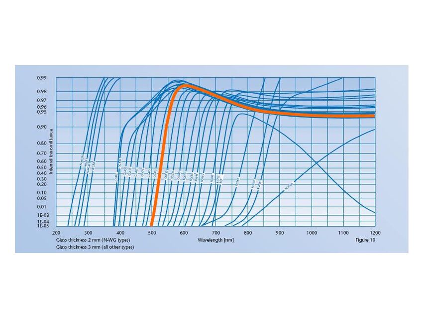
through the system and may not be completely removed by the Dichroic Beam Splitters. Both Red and IR cameras shall
implement OG530 blocking filters for Window 1. Error! Reference source not found. displays the internaltransmission of the blocking filter. As required, the filter blocks out the light blueward of 500 nm and transmits the light
redward of 600 nm.
To prevent dewing and frosting, a sealed gap is provided between the two windows to protect the colder window
(Window 2) from exposure to humid air by the gap and by the presence of Window 1. Window 1 will be at room
temperature and should not experience condensation.
Fig 29. Internal transmission curve for 3 mm thick OG530 glass filter (orange line). Data from Schott Glass Filter catalog
The Camera Field Flattener Lens produces a flat image plane so that the light can be imaged onto a CCD. The Camera
produces an image plane that must interface to the detector. Camera focus is achieved by piston and tilt movement of the
cryostat assembly containing the Windows, Field Flattener Lens, and CCD.
Channel Device Coating
Blue E2V CCD231-84-0-141 Standard 16 micron Astro Broadband
Green E2V CCD231-84-0-E56 Standard 16 micron Astro Midband
Red E2V CCD231-84-0-E24 Deep depletion 40 micron Asro ER1
With fringe suppression
IR E2V CCD231-84-0-E24 TBD
Fig 30. CCD type for each of the channels
Fig 31. Front View of e2v CCD231-84 Detector (lying on its side)7. Instrument frame
The frame is designed to achieve a light weight and stiff structure that is dimensionally stable.
The plate structure is built around the optical components in such a way that the neutral axis falls together with the
optical axis. Bending effects of the frame on the optical components will therefore be minimized. The optical
components and assemblies way over a hundred kilograms and require a stiff mount to create a sufficiently high Eigen
frequency. The instrument is isolated from the ground vibrations by pneumatic isolators.
Dynamical analyses of the instrument show the Eigen frequencies can be well decoupled from those of the isolators. The
isolators are specified to filter out 98% of the floor vibrations above 10 Hz. The Eigen frequency ranges from 3-5Hz
where the frame has a rigid body mode on the stiffness of the isolator.
Thermal stability is achieved by placing the heat sources away from the instrument, insulation and active thermal control
of the room. The material choice for the frame is aluminum. The good conductivity ( k ≈171W/m/K) minimizes the
temperature gradients over the 4.5 x 3.5 meter instrument. Temperature gradients result in misalignment of the optical
components while homogeneous temperature changes only causes defocusing which is less stringent. The large heat
capacity of aluminum (C ≈ 960J/kg/K) means a 0.1 Kelvin temperature variation requires 76.8 kilojoules for a 800 kg
structure. This is equivalent to an absorbed power of 21Watts over one hour. This gives a guide line for the effort needed
to control the temperature and dissipated heat.
Fig 32. CAD model representation of the HERMES space frame.
The required stability can be split up in a long term and a short term stability requirement.
The long term stability requirement is set by the required image quality and is determined by the misalignment of the
optical components.
The short term stability requirement is much more stringent as it is set by the required resolution and accuracy of the
spectral measurements.Optical analyses over the full instrument have been performed with realistic assumptions for the individual
displacements as thermal drift is interrelated. For the collimator mirror this results in the following values, see Table 5.
Stability Radial Axial Tip/tilt
Long term 200µm 200 µm 30 Arcsec
Short termFig 34. Location of HERMES (green) with respect to spectrograph AAOmega in the West Coude room, AA-Telescope. 8.
Grating ghosts

      Fig 35. Simulated images of the littrow ghost. Input continuum spectra are seen in the top portion, ghost images are seen in
           the lower half of the image.

9. Efficiency model

                                                         REFERENCES
[1]
    Bland-Hawthorn, J. and Freeman, K. C., “Galactic history: formation & evolution”, Memorie della Societa
    Astronomica Italiana, 77, 1095-1102 (2006).
[2]
    Bland-Hawthorn, J. and Freeman, K. C., “Galaxy Genesis – Unravelling the Epoch of Dissipation in the Early
    Disk”, Pub. Astron. Soc. Australia, 21(2), 110-120 (2004).
[3]
    Freeman, K. and Bland-Hawthorn, J., “The New Galaxy: Signatures of Its Formation”, Ann. Rev. Astron. and
    Astrophys., 40, 487-537 (2002).
[X] Goodwin, M., Smedley, S., Barnes, S., Farrell, T., Barden, S, “Data simulator for the HERMES instrument”, Proc.
SPIE 7735,(2010)
You can also read