Ivan Kukolj, Armin Iravani & Finn Ouchterlony
←
→
Page content transcription
If your browser does not render page correctly, please read the page content below
Using Small-scale Blast Tests and
Numerical Modelling to Trace the Origin of
Fines Generated in Blasting

Ivan Kukolj, Armin Iravani & Finn
Ouchterlony

BHM Berg- und Hüttenmännische
Monatshefte
Zeitschrift für Rohstoffe, Geotechnik,
Metallurgie, Werkstoffe, Maschinen-
und Anlagentechnik

ISSN 0005-8912

Berg Huettenmaenn Monatsh
DOI 10.1007/s00501-018-0778-9

                                         1 23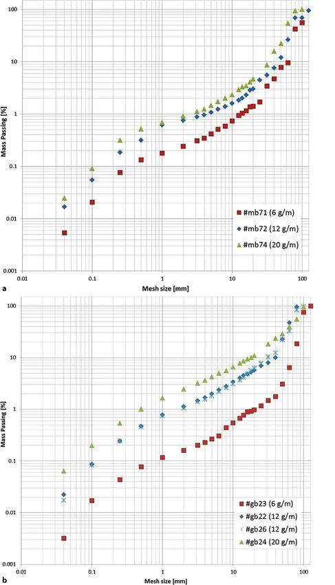
Your article is published under the Creative
Commons Attribution license which allows
users to read, copy, distribute and make
derivative works, as long as the author of
the original work is cited. You may self-
archive this article on your own website, an
institutional repository or funder’s repository
and make it publicly available immediately.

1 23
Originalarbeit

BHM
https://doi.org/10.1007/s00501-018-0778-9
© The Author(s) 2018

Using Small-scale Blast Tests and Numerical Modelling to
Trace the Origin of Fines Generated in Blasting
Ivan Kukolj, Armin Iravani, and Finn Ouchterlony

Chair of Mining Engineering and Mineral Economics, Montanuniversitaet Leoben, Leoben, Austria

Received August 30, 2018; accepted September 5, 2018

Abstract: Waste fines from rock breakage often negatively       chische Wissenschaftsfonds (FWF) fördert ein Projekt zur
influence economics and environment. The Austrian Sci-          Untersuchung der Ursache von Feinanteilen durch Ana-
ence Fund (FWF) sponsors a project to investigate the cause     lyse der Zerkleinerung in kleinmaßstäblichen Sprengver-
of the fines by studying blast fragmentation throughout         suchen und numerische Modellierung. Die Tests umfas-
small-scale blast tests and numerical simulations. The tests    sen Sprengversuche an Granit- und Mörtelzylindern mit 6,
include blast-loading confined granite and mortar cylinders     12 und 20 g/m PETN Sprengschnur. Die dynamische Riss-
by detonating cord with 6, 12, and 20 g/m of PETN. The          bildung an der dem Initiationspunkt gegenüberliegenden
blast-driven dynamic cracking at the end face of the cylinder   Stirnseite des Zylinders wird mit einer Hochgeschwindig-
opposite to the initiation point is filmed with a high-speed    keitskamera aufgenommen. Im Anschluss an die Aufnah-
camera. The filming is followed up by an analysis of sur-       me erfolgt eine Analyse der oberflächlichen und inneren
face and internal crack systems and sieving of the blasted      Risssysteme sowie eine Siebanalyse des gesprengten Ma-
cylinders to quantify the amount of fine material created.      terials, um die Masse des entstehenden Feinmaterials zu
The numerical simulations cover the blast fragmentation         quantifizieren. Die numerischen Simulationen modellieren
of a mortar cylinder. These simulations use Finite and Dis-     die Zerkleinerung eines Mörtelzylinders. Es werden Fini-
crete Element Methods (FEM, DEM) with explicit time inte-       te- und Diskrete-Elemente-Methoden (FEM, DEM) mit ex-
gration. The model cylinders are loaded by a pressure evo-      pliziter Zeitintegration verwendet. Die Modellzylinder wer-
lution acting on the borehole wall. Both methods produce        den durch eine, auf die Bohrlochwand wirkende, Druck-
realistic crack patterns, consisting of through-going radial    entwicklung belastet. Beide Methoden produzieren realis-
cracks with crack intersections around a crushed zone at the    tische Rissmuster, bestehend aus durchgehenden radialen
borehole. Furthermore, the DEM models have also yielded         Rissen mit Rissübergängen (Vereinigung und Unterteilung)
realistic fragment size distributions (FSD). The paper cov-     rund um eine Zermalmungszone am Bohrloch. Darüber hi-
ers the present progress of the ongoing project and related     naus haben die DEM-Modelle auch eine realistische Korn-
future work.                                                    größenverteilung geliefert. Der Beitrag behandelt den ak-
                                                                tuellen Fortschritt des laufenden Projekts sowie damit ver-
Keywords: Blast-induced fines, Blast tests, High-speed          bundene zukünftige Arbeiten.
photography, FEM, DEM, Dynamic cracking, Blast
fragmentation                                                   Schlüsselwörter: Sprenginduzierte Feinanteile,
                                                                Sprengversuche, Hochgeschwindigkeitsfotografie, FEM,
Untersuchungen zur Entstehung von sprenginduzierten             DEM, Dynamische Rissbildung, Sprengzerkleinerung
Feinanteilen anhand von kleinmaßstäblichen
Sprengversuchen und numerischer Modellierung
                                                                1. Introduction
Zusammenfassung: Bei Gesteinssprengungen entstehen-
de, nicht verwertbare Feinanteile haben oft einen negativen     The amounts of mineral fines that are associated with raw
Einfluss auf Umwelt und Wirtschaftlichkeit. Der Österrei-       materials extraction have practical consequences. One
                                                                concern is the sustainability of natural resources since
                                                                fines are often an unsellable liability or waste that has cost
I. Kukolj, MSc ()
Chair of Mining Engineering and Mineral Economics,              money and energy to produce and in the end has to be
Montanuniversitaet Leoben,                                      deposited. This reasoning lay behind the EU project Less
Erzherzog-Johann-Str. 3,                                        Fines [1]. The health aspects of mineral fines have again
8700 Leoben, Austria                                            come into focus, so sources of respirable dust and miti-
ivan.kukolj@unileoben.ac.at

BHM                                                    © The Author(s)                                            Kukolj et al.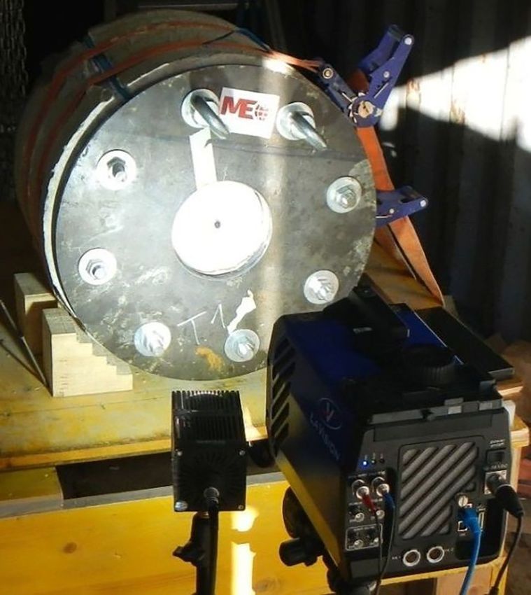
Originalarbeit
Fig. 1: Volume of crushed ma- Fig. 3: Post-blast cross sec-
terial around an extended 2D tion through blasted confined
blast-hole (Fig. 2 in [7]); the mortar cylinder [9]
crushed zone volume Vc is an-
nular and the breakage zone
volume Vb, which also gener-
ates crushed fines, is made up
of the n partial volumes of the
star arms
Fig. 2: Sieving curves for blasted multilayered Ø300×600-mm cylinders
ofmortar;comparisonofØ120-mmblack corewithyellow(Ø120–200 mm)
+ green layers (Ø200–300 mm) [8]
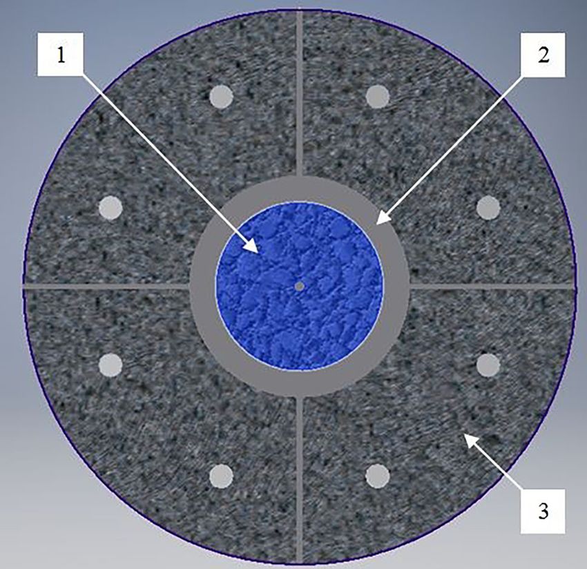
Fig. 4: Prepared blast chamber (transverse cross-section) (1—Blast
cylinder; 2—Damping layer; 3—Blast chamber)
gation effects are studied in the ongoing EU Horizon 2020 lar crushed-zone model was extended to a star-shape one
project “Sustainable Low Impact Mining, SLIM” [2, 3]. (Fig. 1; [7]).
Blasting is a major producer of waste fines, crushing and Blasting tests with layered cylinder specimens [8] con-
milling another. Blasting is a highly dynamic process and tradict the predictions of the star-shaped CZM (Fig. 2).
the crack growth that defines breakage is a major source of Firstly, the sieving curves for the layers are quite similar in
fines. Such crack-generated fines (CGF) are also produced shape and the core region contains fragments well beyond
by crushing and grinding. Fines are inherently related to 1 mm in size. Secondly, there is a cross-over point (0.25 mm
the amount of energy required in comminution. Most of in Fig. 2) above which the outer layers contain more fine
the area created resides in the fines and this area then de- material than the core. Consequently, more –1 mm fines
termines the consumed comminution energy [4]. A better are created outside the black core than inside it.
knowledge of how CGF are generated may also help to im- Post-mortem crack patterns are not as simple either as
prove blasting and crushing practices and to suppress the the CZM (Fig. 3; [9]). Here the cracks have seemingly run
amount of CGF at the source rather than dealing with them along crooked paths, branched, merged, and left debris
afterwards. along the crack paths.
Blast generated fines are often considered to originate Statistical models of brittle fragmentation [10, 11] point
mainly from the annular crushed zone around a blast hole, in the same direction, that instability of fast propagating
which contains only –1 mm material, and fragmentation cracks leaves behind a trace of small fragments along their
models were built around this; e. g. the CZM or crush zone propagation paths, but this has not been observed in rock
model [5, 6]. It implies that fragment size is (almost) solely under blasting-like conditions. More arguments are pro-
defined by the distance to the blast hole, the finest mate- vided in [12].
rial created at the borehole wall and fragment size, thus, This led to the FWF-sponsored project P27594-N29:
increasing with distance from the blast hole. The circu- “Fines generated by dynamic crack propagation, as in
blasting of rock-like materials,” which ends Dec 31, 2018.
Kukolj et al. © The Author(s) BHM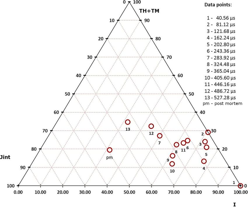
Originalarbeit

TABLE 1
Measured material properties
 Property                                               Granite                  Mortar                  Damping
                                                        Mean        St.dev       Mean       St.dev       Mean       St.dev
 UCS [MPa]                                              171.50      9.00         27.70      1.10         –          –
 Brazilian tensile strength [MPa]                       10.85       1.52         2.90       0.49         –          –
 Density [g/cm3]                                        2.70        0.01         1.66       0.01         2.12       0.08
 Young’s modulus [GPa]                                  65.30       0.83         12.20      0.31         –          –
 Poisson’s ratio [–]                                    0.24        0.02         0.23       0.05         –          –
 P-wave velocity [m/s]                                  4908        111          3069       62           1210       274
 S-wave velocity [m/s]                                  3212        150          2065       40           643        79

Two main project objectives are to: i) determine the im-              The filming set-up (Fig. 6) records the dynamic crack de-
portance of the dynamic mechanism for CGF by capturing             velopment, in most cases, with 24,656 fps at 336 × 336 pix-
images of branching at a moving crack tip and ii) compare          els.
the measured fragment size distribution (FSD) with models
based either on the mechanism of crack branching and
merging or other mechanisms. The first part of this project        2.2 Numerical Modelling
is described in [13, 14], progress in numerical simulations
in [15], and the present state in this paper. It is divided into   2.2.1 Modelling in Abaqus
an experimental part and a part with numerical simulations.
                                                                   Numerical modelling of blast fragmentation was done us-
                                                                   ing the finite element method (FEM) and the discrete el-
2. Methodology                                                     ement method (DEM) [14]. The FEM approach (Abaqus)
                                                                   is suitable for modelling blast-induced damage, though
2.1 Small-scale Blast Tests                                        presently quite limited for fragmentation analysis [14].

The blast tests [13] include controlled blast loading of a con-    2.2.2 HiDEM Model
fined hollow cylinder whilst the resulting dynamic cracking
is filmed at its frontal end face by means of high-speed           Blast cylinders are modelled with a 3D discrete element
photography.                                                       code (HiDEM) [11, 18]. A dynamic sedimentation method is
   The cylinder is made of mortar or granite, Ø150 × 300 mm        used to generate the initial random structure of the model
in size, with a Ø10-mm central axial borehole. The produc-         composed of rigid spheres of 2-mm and 3-mm diameter.
tion of the blast cylinders is described in [13].                  Contacts between the particles are modelled using mass-
   The loading is achieved by detonating a decoupled PETN          less beams. The interaction potential between two particles
(Pentaerythritol tetranitrate) cord (6, 12, or 20 g/m) inside      is defined by the Euler-Bernoulli (EB) beam model. Esti-
the borehole. The detonation propagates along the cord             mates of the beam elastic energy are provided in [18]. The
towards a stemming plug at the frontal end face with the           beams break due to excerted tension, shear, or bending
velocity (VOD) of about 7300 m/s [16].                             beyond the fracture limit (Fig. 4 in [18]).
   The cylinder is radially confined by a 25-mm-thick damp-            The particle-motion equation is given in [14]. The model
ing layer inside a blast chamber (Fig. 4). The damping ma-         assumes elastic-material behaviour. The stiffness matrix
terial [13] is a commercial concrete mixture, cured for one        for linear-elastic EB beams under small deformation is
day. It improves the acoustic-impedance matching of prop-          provided in [18]. The modelled material has an elastic
agating shock waves and protects the chamber.                      modulus of E = 19.7 GPa and a Poisson’s ratio of ν = 0.19,
   Table 1 shows measured material properties of the blast         which is somewhat representative of the blast-test mortar.
cylinders and the damping layer.                                   The stochastic mechanical behaviour of granular disor-
   The blast chamber (Fig. 5) includes four concrete seg-          dered materials was modelled using beams with reduced
ments, axially connected with two metal plates. The seg-           stiffness. These beams were randomly selected to have
ments are designed to radially move about 5 mm during the          their stiffness reduced to 10% of the original value. Here,
blast, acting as ‘impulse traps’ [17]. The rear metal plate in-    the fracture criterion [11, 18] was described by the elastic-
cludes an opening for inserting the cord. The frontal metal        strain threshold εcrit = 0.0003.
plate includes an opening, allowing filming of the frontal             The modelled mortar cylinders are Ø140 × 280 mm in size
end face through a protective polycarbonate window.                with a Ø10-mm borehole. The blast loading is radially ap-
   The filming [13] captures crack development at the end          plied onto the borehole wall according to a pressure-time
face following the detonation. The cracking at the end face        function [14]. The modelled VOD is the same as in the blast
starts about when the detonation front reaches the stem-           tests. A simplified post-peak pressure drives all particles
ming plug, which is seen as slight movement of the plug            outwards with Ppost = 0.0025Ppeak. The modelling uses three
and occasionally a dimmed detonation-flash around it.              peak pressures of 166 MPa, 85 MPa, and 35 MPa, equiva-

BHM                                                      © The Author(s)                                            Kukolj et al.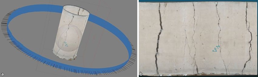
Originalarbeit
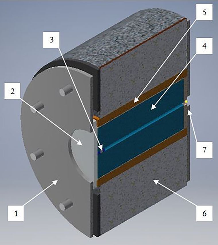
Fig. 5: Prepared blast chamber (axial cross-section) (1—Frontal end Fig. 6: High-speed filming set-up for the blast tests
metalplate; 2—Protectivewindow; 3—Boreholewith stemming; 4—Blast
cylinder; 5—Damping layer; 6—Chamber segment; 7—Rear-end metal
plate)
lent to 20 g/m, 12 g/m, and 6 g/m of PETN [14]. In addition, where the boulder intensity nb is given by the characteristic
20 mm of stemming was included. Quiet boundary con- boulder size sb and
ditions are applied to the mantle to avoid cracking due to
reflected tensile waves. nb (s) = exp(–s/sb ) (2)
2.2.3 Simplified n(s) Model With the proper transformation from s to r, i. e. ds ∝ r2 dr
for D = 3, leaving the exponential part of the second term in
When blasted, the cylinder expands radially, inducing tan- the n(s) formula and integrating the n(s), the mass passing
gential tension and tensile cracks. In the crushing process, fraction at screen size r (MPF(r)) can be approximated for
fragments are broken by continual shear deformation [19]. fragments smaller than boulders [15]:
Such a process has a power-law FSD ncrush(s)ds = C1s-β ds
[11], where C1 is a constant and β indicates the degree of MPF(r) = fcr [1.0–(r/rgrain )(–3β+6) ] + fbm (r/rmax )(–2α+6) (3)
crushing/grinding, being β ~ 1.8–3.5 when dimension D = 3
[11, 15]. Dimensionless size s is measured in number of where fbm and fcr determine the mass fraction of fragments
grains composing a fragment [15]. formed in the branching-merging and the crushing process,
The dynamic tensile cracks can easily become unstable, rgrain is the approximated diameter of the material grain
branch, and further merge, forming fragments. This inher- size, and rmax is the approximated diameter of the largest
ently-universal process leads to a characteristic FSD [11, fragment.
20]. The number of fragments nbm(s) of size s in an inter-
val ds can be written as nbm(s)ds = C2s-α exp(-s/C3)ds with
α = (2D–1)/D, where C2 and C3 are non-universal constants 3. Preliminary Results
[11, 15].
If n(s) describes the number-density of fragments with 3.1 Crack Patterns
s number of grains, the FSD, or the number of fragments in
a size-interval ds, can then be written as [15]: The high-speed images (Fig. 7) show more intensive crack-
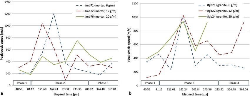
ing with the increase of charge. Similarly, crack patterns are
n(s)ds = C1 s–β ds + C2 s –α exp(–s/C3 )ds + nb (s)ds (1) denser and develop earlier in granite than in mortar. The
high-speed images of both mortar and granite shots show
three phases of crack development [13].
Firstly, following the plug movement, initial cracks
emerge and propagate mainly in the radial direction. In
Kukolj et al. © The Author(s) BHM
Originalarbeit

Fig. 7: High-speed and post-mortem end-face images of the cylinders with respect to the charge and material

Fig. 8: Peak crack speed in blast cylinders with respect to material, charge amount, and elapsed time (a Mortar curve set; b Granite curve set)

BHM                                                                © The Author(s)                                                          Kukolj et al.
Originalarbeit

Fig. 9: Post-mortem mantle image (a Processing; b “Unfolded” mantle, cylinder #mb71)

                                                                          (Jint: X, Y, and TI), borehole intersections (TH), mantle inter-
                                                                          sections (TM), and crack-end nodes (I).
                                                                              The analysis quantifies the development of the features
                                                                          in the images with respect to time, from 40.56 μs to 527.28 μs
                                                                          and finally to the post-mortem state (pm). The results are
                                                                          presented in a ternary diagram with respect to the percent-
                                                                          age of the feature categories (Fig. 11).
                                                                              The results show that the percentage of crack intersec-
                                                                          tions rapidly increases and the percentage of end nodes
                                                                          drops during the second phase, as the initial smaller cracks
                                                                          coalesce.
                                                                              The number of active end nodes (i. e. propagating crack
                                                                          tips) and intersections both increase with the increase of
                                                                          charge and more so in granite than in mortar.
                                                                              Fig. 12 shows resulting 3D crack networks from the mod-
                                                                          elling with respect to the three loading levels at t = 400 µs.
                                                                          By increasing the loading level, the internal damage in-
                                                                          tensity increases. Accordingly, the crack system becomes
                                                                          more complex, increasing in number of main radial cracks
                                                                          and intersections.

Fig. 10: Topological representation of crack-pattern features
                                                                          3.2 Fragmentation Analysis of Blasted Cylinders

the second phase, the crack-propagation speed reaches                     Fig. 13 shows sieving FSD curves of selected blast cylin-
its peak and quickly drops with multiple cracks branching-                ders. The curves shift upwards to contain larger fractions
merging (Fig. 8). After the second phase, the main cracks                 of fines when the charge is increased, in accordance with
have reached the borehole and/or the mantle and end-face                  the Natural Breakage Characteristics (NBC) properties [4].
spalling with fumes leakage may occur.                                    The curve-fitting procedure is ongoing.
    The post-mortem crack patterns are observed at the end
face (Fig. 7), on the mantle, and internally through com-
puter tomography (CT) [13].                                               3.3 Numerical Estimates of Fragmentation and
    The mantle crack patterns are firstly photographed and                    Fines Sources
then processed in Agisoft PhotoScan® to produce a 3D
model of the mantle, which is then projected onto a 2D                    Fig. 14 shows FSD curves obtained with HiDEM modelling.
image for further analysis (Fig. 9).                                      A fragment is defined by the number of connected parti-
    So far the CT cross-sections and mantle images indi-                  cles N and the screen size is that of the diameter of a vol-
cated that the number of main cracks and the number of                    ume-equivalent sphere. The curves represent the mass-
main intersections basically do not change in the axial di-               passing fraction of the model for different blast-loading
rection [13].                                                             levels. The curve with Ppeak = 166 MPa is similar to the siev-
    The crack patterns in the high-speed and post-mortem                  ing curves and well approximated by the Swebrec function
images are traced and topologically analysed, similarly as                [22]. The FSD curves from the DEM simulations also show
in [21]. This includes decomposition of a crack network into              an NBC-like relationship.
topological features (Fig. 10): branches, crack intersections

Kukolj et al.                                                   © The Author(s)                                                      BHM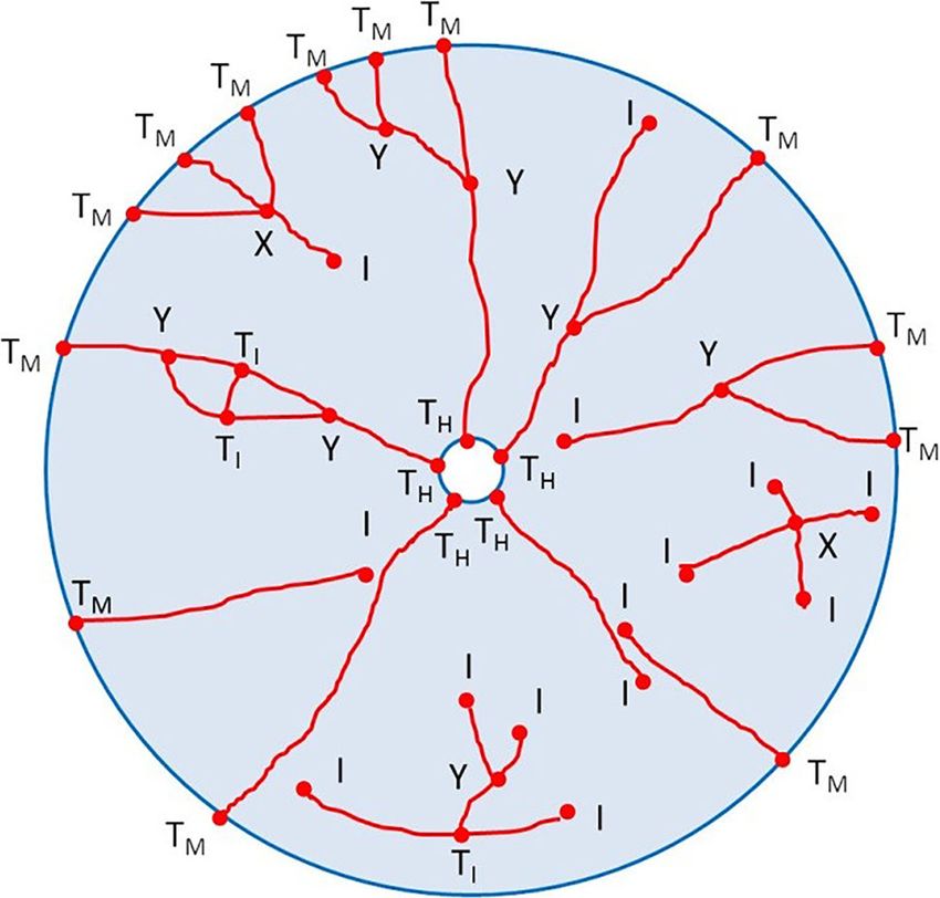
Originalarbeit

Fig. 11: Results from the
topological analysis (cylinder
#mb75); the data points relate
to crack-pattern state with
respect to elapsed time

Fig. 12: Crackpatternsofmod-
elled cylinders

   At 35 MPa and 85 MPa, the mass-passing curves indi-        banded at radii r = 30 mm and r = 50 mm, creating three con-
cate the “dust and boulders” phenomenon. The curve with       centric regions. A routine calculates the absolute mass of
Ppeak = 35 MPa contains 94% of the cylinder mass in one       very fine particles containing only one DEM particle in each
boulder. The curve with Ppeak = 85 MPa contains a wider       region. Fig. 15 shows that the absolute mass of the fines
range of fragment sizes and four boulders, with almost 50%    in region 3 (50 mm < r < 70 mm) is larger than in region 1
of the cylinder mass. This results from blasting below the    (5 mm < r < 30 mm), thus confirming the results from [8].
critical charge level [9, 12].
   By using Eq. 3, the percentage mass fraction of frag-
ments formed by branching-merging and crushing [15] can       4. Conclusions
be determined for the results (Table 2). The size of the
branching-merging fragments ranges from a single DEM          The ongoing project studies dynamic mechanisms behind
particle to a maximum value, which depends on the ap-         blast-induced fines.
plied loading level. Similar to the MPF, the size of these       The filming shows a three-phase crack-pattern develop-
fragments is approximated by the diameter of the volume       ment. The main cracks and intersections in mortar are more
equivalent sphere.                                            numerous and appear earlier with higher charge and the
   Simulations have also been conducted with radially-lay-    same tendencies are observed in granite, but at a higher
ered mortar cylinders, like those in [8]. The cylinders are   level. They are detectable before the third phase and do

BHM                                                  © The Author(s)                                          Kukolj et al.
Originalarbeit

Fig. 13: Selected sieving
curves of blasted cylinders
(a Mortar curve set; b Granite
curve set)

Kukolj et al.                    © The Author(s)   BHM
Originalarbeit

Fig. 14: FSD curves of modelled cylinders                       Fig. 15: Absolute mass of fine-particles with respect to the radius from
                                                                the borehole

 TABLE 2
 Percentage mass fraction of fragments formed by crushing, branching-merging, and in boulders
 Ppeak     Fragment mass percentage [%]                                          Max. diameter of branching-merging
 [MPa]     Crushing     Branching-merging   Boulders   Branching-merging         fragments
                                                       (
Originalarbeit
4. Steiner, H. J.: The significance of the Rittinger equation in present- ceedings of 12th International Symposium on Rock Fragmentation
day comminution technology, in: Proceedings of 17th International by Blasting, 2018, pp 483–494
Mineral Processing Congress, Bd I, 1991, pp 177–188 14. Iravani, A.; Kukolj, I.; Ouchterlony, F.; Antretter, T.; Åström, J.:
5. Thornton, D.; Kanchibotla, S. S.; Brunton, I.: Modelling the impact Modelling blast fragmentation of cylinders of mortar and rock, in:
of rockmass and blast design variation on blast fragmentation, in: Schunnesson, H.; Johansson, D. (eds.): Rock Fragmentation by
Marton, A. (ed.): Proceedings of Explo 2001 Conference, AusIMM: Blasting, Proceedings of 12th International Symposium on Rock
Carlton (u. a.), 2001, pp 197–205 Fragmentation by Blasting, 2018, pp 597–610
6. Esen, S.; Onederra, I.; Bilgin, H. A.: Modelling the size of the crushed 15. Iravani, A.; Åström, J. A.; Ouchterlony, F.: Physical origin of the
zone around a blasthole, Intenational Journal of Rock Mechanics fine-particle problem in blasting fragmentation, Physical Review
and Mining Sciences 40(2003), pp 485–495 Applied, 10, 034001 (2018). https://doi.org/10.1103/PhysRevApplied.
7. Onederra, I.; Esen, S.; Jankovic, A.: Estimation of fines generated 10.034001
by blasting—applications for the mining and quarrying industries, 16. Schimek, P.: Improvement of fragmentation by blasting, Diss.,
Mining Technology, Transactions of the Institute of Mining and Met- Leoben, Montanuniv., Lehrst. f. Bergbaukunde, Bergtechnik und
allurgy A:113 (2004), pp A1–A11 Bergwirtschaft, 2015
8. Svahn, V.: Generation of fines in bench blasting, Lic. thesis, Gothen- 17. Sun, C.: Damage zone prediction for rock blasting, Doctoral Thesis,
burg, Chalmers Univ. Technology, Dept. of Geology, Publication The University of Utah, Dept. of Mining Engineering, 2013
A104, 2003 18. Åström, J. A.; Riikilä, T.I.; Tallinen, T.; Zwinger, T.; Benn, D.; Moore,
9. Johansson, D.: Fragmentation and waste rock compaction in small- J. C.; Timonen, J.: A particle based simulation model for glacier
scale confined blasting, Lic. thesis 2008:30, Luleå: Luleå Univ. Tech- dynamics, The Cryosphere 7(2013), Nr. 5, pp 1591–1602
nology, 2008 19. Åström, J. A.; Timonen, J.: Spontaneous formation of densely
10. Åström, J. A.; Ouchterlony, F.; Linna, R. P.; Timonen, J.: Univer- packed shear bands of rotating fragments, The European Physical
sal dynamic fragmentation in D dimensions, Physical review letters Journal E 35 (2012), p 40
92(2004), Nr. 24, pp 245506–1/4 20. Kekäläinen, P.; Åström, J. A.; Timonen, J.: Solution for the fragmen-
11. Åström, J. A.: Statistical models of brittle fragmentation, Advances tation-size distribution in a crack branching model of fragmentation,
in Physics 55(2006), Nr. 3–4, pp 247–278 Physical Review E 76, 026112 (2007)
12. Ouchterlony, F.; Moser, P.: On the branching-merging mechanism 21. Sanderson, D. J.; Nixon, C. W.: The use of topology in fracture
during dynamic crack growth as a major source of fines in rock network characterization, Journal of Structural Geology 72 (2015),
blasting, in: Singh, P. K.; Sinha, A. (eds.): Rock Fragmentation by pp 55–66
Blasting, Proceedings of 10th International Symposium on Rock 22. Ouchterlony, F.: Fragmentation characterization: the Swebrec func-
Fragmentation by Blasting, USA, Boca Raton (u. a.): CRC Press, tion and its use in blast engineering, in: Sanchidrián, J. A. (ed.):
2012, pp 65–75 Rock Fragmentation by Blasting, Proceedings of 9th International
13. Kukolj, I.; Iravani, A.; Ouchterlony, F.; Weiss, C.; Lubensky, J.: Film- Symposium on Rock Fragmentation by Blasting, Spain, Granada
ing blast fragmentation of rock and mortar cylinders, in: Schunnes- (u. a.): CRC Press, 2009, pp 3–22
son, H.; Johansson, D. (eds.): Rock Fragmentation by Blasting, Pro-
Kukolj et al. © The Author(s) BHMYou can also read