End-To-End Real-Time Visual Perception Framework for Construction Automation
←
→
Page content transcription
If your browser does not render page correctly, please read the page content below
End-To-End Real-Time Visual Perception Framework for Construction
Automation
Mohit Vohra1 , Ashish Kumar1 , Ravi Prakash1 and Laxmidhar Behera1,2 , Senior Member, IEEE
Abstract— In this work, we present a robotic solution to
automate the task of wall construction. To that end, we present
an end-to-end visual perception framework that can quickly
detect and localize bricks in a clutter. Further, we present
a light computational method of brick pose estimation that
incorporates the above information. The proposed detection
arXiv:2107.12701v1 [cs.RO] 27 Jul 2021
network predicts a rotated box compared to YOLO and SSD,
thereby maximizing the object’s region in the predicted box
regions. In addition, precision (P), recall (R), and mean-average- (a) (b)
precision (mAP) scores are reported to evaluate the proposed
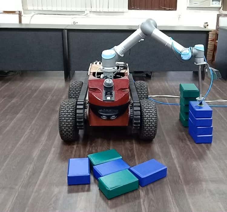
framework. We observed that for our task, the proposed scheme Fig. 1: (a) shows a simple scenario where a pile is located
outperforms the upright bounding box detectors. Further, we near the robotic system, (b) the robotic system mimics wall
deploy the proposed visual perception framework on a robotic
system endowed with a UR5 robot manipulator and demon-
building task i.e. detects pile, selects a target brick and
strate that the system can successfully replicate a simplified constructs a wall on its side in a fully autonomous way.
version of the wall-building task in an autonomous mode.
a sequence of operations: i) Select the appropriate brick from
I. I NTRODUCTION the pile, e.g., the topmost brick, ii) finding the optimal grasp
Manufacturing and construction are one of the widespread pose for the brick, and iii) finally, placing the brick in its
and continuously growing industries. The former has seen a desired place, i.e., on the wall. Humans can do this work very
dramatic increase in production capacity due to the optimiza- quickly and efficiently. However, the robot must perform a
tion of industrial automation, while the latter has adopted complex set of underlying operations to complete the above
automation only marginally [1]. Construction automation steps autonomously [3].
is inherently quite challenging for several reasons. First, In this paper, we aim to deploy a robotic solution for the
the workspace is highly unstructured. Therefore, very high task of construction automation in a constrained environment
precision and robust visual perception, motion planning, and (Fig.1) with limited computational resources (single CPU
navigation algorithms are required for autonomous solutions with I7 processor, 4core, 8GB RAM ). We assume that all
to adapt to different scenarios. Secondly, a mobile manipu- bricks are of equal size, and their dimensions are known. We
lator needs to move between multiple positions, compelling further assume that the wall assembly area and brick piles
us to perform onboard computations for various algorithms. are very close, exempting us from deploying any localization
Therefore, limited memory, power, and computational re- and navigation modules for robots. Thus, the main challenge
sources make this task more challenging. in this task is to detect and localize bricks in the clutter
The process of automation can have a broad impact on the while handling the multiple instances of the bricks. Once
construction industry. First, construction work can continue we have localized the bricks in a clutter, we will use the
without pause, which ultimately shortens the construction above information to estimate the brick pose. Following are
period and increases economic benefits. Also, the essential the main contributions in this paper:
benefits of construction automation are worker safety, quality, • A computationally efficient object detection network for
and job continuity. Towards this end, recently, Construction the detection and localization of bricks in a clutter is
Robotics, a New York-based company, has developed a presented in this paper.
bricklaying robot called SAM100 (semi-automated mason) • A light computational method for estimating brick pose
[2], which makes a wall six times faster than a human. using point cloud data is presented in this paper.
However, their robot required a systematic stack of bricks • All the modules are integrated into a robotic system to
at regular intervals, making this system semi-autonomous, develop a fully autonomous system.
as the name suggests. • Extensive experiments to validate the performance of
One of the primary construction tasks is to build a wall our system.
from a pile of randomly arranged bricks. To replicate the In the next section, we briefly provide a review of state-
simplified version of the above work, humans must complete of-the-art algorithms related to the paper. In the section-III,
1 Authors are with Indian Institute of Technology Kanpur, India,
we formulate the problem statement. The overall approach
{mvohra, krashish, ravipr and lbehera}@iitk.ac.in. and its modules are explained in section-IV. In section-V, the
2 Author is with TCS Innovation Labs, Noida, India experimental study of the algorithm is reported for various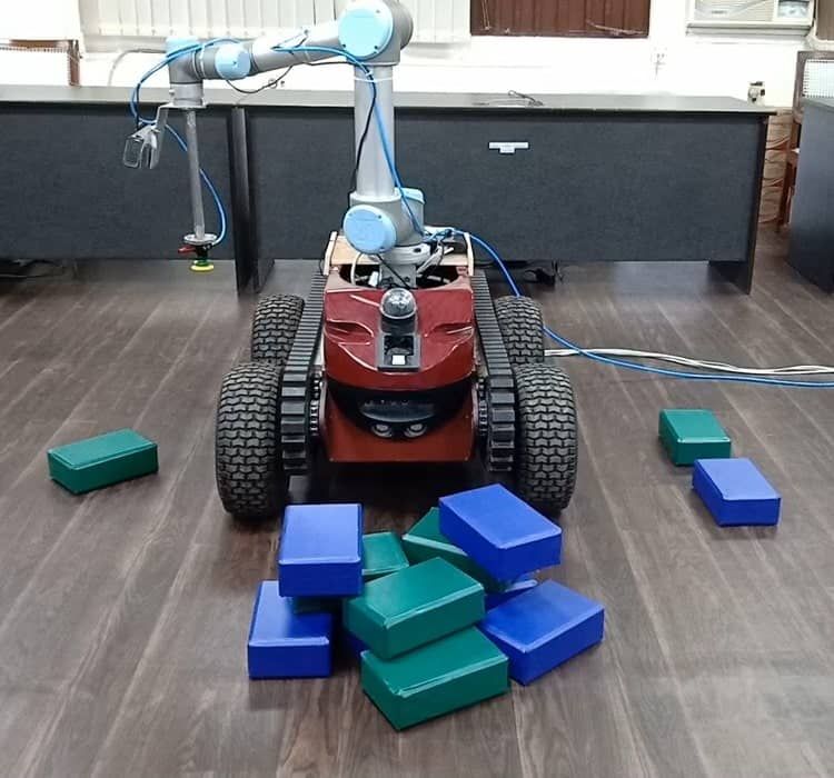
test cases. This paper is finally concluded in section-VI.           presence of an object and its class score at various stages of
                                                                     different spatial resolutions.
                    II. R ELATED W ORKS
A. Object Detection                                                  B. 6D Pose Estimation
   As mentioned in the previous section, the first stage of the         After brick localization, a grasp operation needs to be
construction process is the localization of the target object. In    performed by the manipulator. Choosing an optimal grasp
our case, the target object is referred to as a brick. In general,   configuration is a non-trivial task and remains an open
bricks are arranged randomly. Therefore, the brick must be           problem. The grasp configuration depends on the 6D pose
localized before grasping. The process of brick localization         of the brick. Several Neural-network based pose estimation
falls under the category of the object detection algorithm.          methods exist in the literature [14], [15], but limited memory
We perform a brick localization process in the image space.          resources compel us to use computationally light pose-
Several object detection algorithms exist in the literature.         estimation methods. To this end, several algorithms exist to
Here, we limit our discussion to only Conventional Neural            estimate the object’s 6D poses, which require a high degree
Network (CNN) based methods.                                         of surface texture on the object. In our case, the estimation of
   The RCNN [4] generates object proposals (rectangular              brick poses is quite challenging due to their cubic shape (flat
regions) in the image plane, and a CNN is used to extract            surfaces), which do not have surface textures. Therefore, the
features from the proposed regions, followed by a classifier to      feature point matching technique [16] [17] cannot be used.
classify the proposed regions into N different classes, where        Other approaches [18], [19] consider an earlier model of the
N may vary according to application. In RCNN, most of                object. These methods require a preprocessing step, followed
the time is consumed in proposal generation as this step is          by the correspondence matching process. The matching
performed on CPU, and also inference time increases linearly         process is the most time-consuming component of such
with an increase in the number of proposals. SPPnets [5]             algorithms. Besides, point-to-point matching methods (ICP
were proposed to speed up the RCNN by extracting the                 [20], GICP [21]) are based on local geometric properties.
features for the whole image at once and then cropping               Therefore, these methods can be stuck in local minima when
the feature map corresponding to the proposals. Due to the           aligning the target model with the reference due to flat
multistage nature of the above algorithm, joint training was         surfaces.
required. Fast-RCNN [6] proposes an improved approach
that is relatively faster and requires single-stage training.                         III. P ROBLEM S TATEMENT
A further improved version of Faster-RCNN [7] was also               A. Object Detection
proposed in which proposals are generated within the CNN,
called a Region Proposal Network (RPN). The RPN was                     As mentioned in previous sections, the main challenge is
the key improvement in improving the overall algorithmic             to identify the bricks in a clutter. All state-of-the-art object
real-time performance. All the methods discussed above               detectors predict the upright or straight bounding box, which
predict an upright bounding box around the detected object.          has three limitations:
In addition to the target object region, the predicted box              • The bounding box corresponding to the rotated or tilted

may contain non-object regions or backgrounds. Hence, to                  object contains a significant non-object region (Fig. 2a).
minimize the background in the detected boxes, various                    Thus, it requires an additional step to extract object
solutions are present in the literature. For example, in [8],             information, like object segmentation in the bounding
the author predicts a rotated bounding box from the set of                box region.
prior rotated boxes (anchor boxes). Similarly, Mask-RCNN                • If two or more objects are very close to each other.

[9] can predict the bounding box and mask of the object                   The corresponding bounding boxes will have non-zero
simultaneously, which is known as instance detection and                  intersecting regions (Fig. 2b). Thus, additional steps are
segmentation.                                                             required to handle intersecting regions, as this region
   All the algorithms mentioned above consists of two steps;              may contain clutter for one box or an object part for
i) generation of object proposals or anchor boxes (axis-                  another box.
aligned or rotated), ii) classification (or regressing) the             • If the intersecting regions are significant, after applying
proposals using a CNN with a backbone such as VGG                         non-maximal-suppression (NMS), neighbor detection
[10], ResNet [11]. Thus the performance of the algorithm                  may be missed [22], as shown in Fig. 2c.
depends on the proposal generation process. On the other
hand, authors of You Only Look Once (YOLO-v1) [12]
have proposed a single network for object detection which
divides the image into grid cells and directly predicts the
fixed number of bounding boxes, corresponding confidence
scores, and class probabilities for each grid cell. In the same
direction, single shot multibox detector (SSD) [13] is another        (a) Predicted Boxes   (b) Boxes Overlap     (c) After NMS
variant of a single-stage object detector. In this variant, multi-
resolution object detection is performed, i.e., detecting the          Fig. 2: Nearby predictions can be missed due to NMS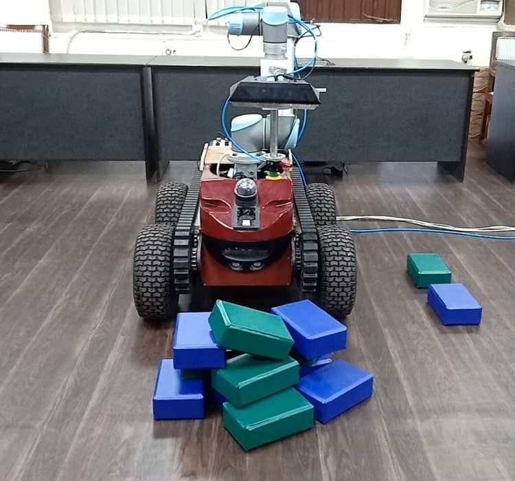
Fig. 3: A synthetically generated sample
To compete with the above limitations, we designed a
CNN-based model to detect and localize bricks by predicting
rotated boxes. An additional degree of freedom, i.e., the box’s Fig. 4: Proposed Network
angle, allows the network to predict the box with greater blue brick, green brick) exists within that grid. If there is
alignment with the target object. Since most of the area inside no centroid in the grid, then we will assign the probability
the rotated bounding box corresponds to the target object, of 1.0 to the background label. Suppose a centroid exists
we can directly use the region corresponding to the rotated within a grid. Corresponding bounding box parameters are
bounding box to extract the target object’s information, x, y, w, h, θ, where x, y is the offset between the rotated
avoiding any additional computations. A detailed description bounding box center and the topmost grid corner. Parameters
of the proposed model is given in Section-IV. w, h, θ are width, height, and orientation of the bounding
B. 6D Pose Estimation box, respectively. We scale the bounding box parameters in
the range of (0, 1), where the maximum value of offset is
As mentioned earlier, the bricks used in the experiments
16 pixels. The box’s maximum dimension can be 480 × 640
have a flat and textureless surface. Therefore, feature match-
pixels, and the maximum orientation value is 3.14 radians.
ing methods for pose estimation are unreliable in our experi-
Thus for each image, we have an output tensor of size
ments, as the number of features is less and not very distinct.
30 × 40 × 8. Further, if multiple centroid points exist in
Since the bricks used in our experiments have a cuboidal
a single grid, we select the centroid point corresponding to
shape, if we can estimate the pose of at least one surface of
the mask, which has a larger fraction of the complete mask
the brick, this information is sufficient to estimate the pose
in that grid.
of the entire brick. The brick has six faces, and each face
has a specific relative pose with a local brick frame. Hence B. Rotating Box Network
to estimate the brick pose, we have to identify the brick Fig. 4 represents the network architecture. For each block,
surface (out of six surfaces), estimate the surface pose, and the size of the input and output feature map is mentioned.
use relative transformations to get the complete brick pose. Also, we use the ReLU activation function after each layer.
A brief description of the pose estimation method is given The SSD architecture inspires the proposed rotating box net-
in the section - IV-C. work architecture. In SSD, shallow layer features and depth
IV. T HE P ROPOSED F RAMEWORK layer features are used for final predictions. Similarly, in the
proposed network, features from individual shallow layers
A. Dataset
are processed, concatenated, and passed through a series of
We collect 30 images for each class of brick (e.g., blue fully convolutional layers for final prediction. Unlike SSDs,
and green) using Kinect. Images are collected, such that each the proposed network prediction does not use any anchor
image has an isolated brick with a different pose. A manual boxes. Instead, it predicts an additional degree of freedom
mask is generated for each image. Following [23], the raw (angle of the box), and thus the predicted bounding boxes
images and the corresponding masks are used to synthesize can align more accurately than the constrained bounding box.
the cluttered scenes. A dataset of 10k training images and In order to train the network for predicting rotated boxes,
5k test images are generated. We generate ground truths for the input to the network is the raw image, and the output
synthetic images such that a unique instance-ID, as opposed of the network is a tensor of size 30 × 40 × 8. Further,
to semantic segmentation, is assigned for each brick instance. we use a cross-entropy loss for the class probabilities and
A random sample from the data set is shown in Fig. 3. a regression loss for the bounding box parameters. Overall
Furthermore, for each mask instance, we generate a rotated loss for the network is the average of both losses. Further, to
box using the OpenCV API. avoid any biasing in training because of the large number of
Each image is divided into several grids, where each grid non-object grids as compared to the object grids, we select
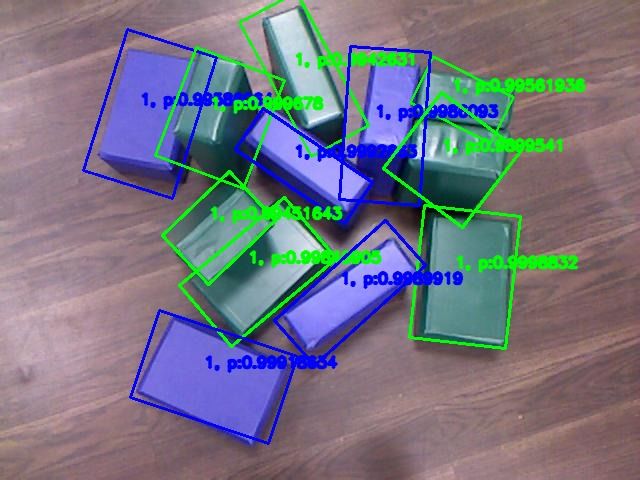
has a size of 16 × 16 pixels. Thus if the raw image has a size positive to negative ratio = 1 : 2 by following [13]. Output
of 480×640, then the total number of the grids are 480 640
16 × 16 , the model for the different arrangement of bricks in a variety
i.e., 30×40. Further, each grid is represented by an 8D vector of backgrounds is shown in Fig. 5.
representing the three-class probabilities (blue brick, green
brick, or background) and five bounding box parameters C. Pose Estimation
x, y, w, h, θ. For each grid, class probabilities are assigned To estimate the brick pose, as mentioned earlier, we have
if the rotated bounding box’s centroid (corresponding to the to calculate the pose of one of the brick surfaces and use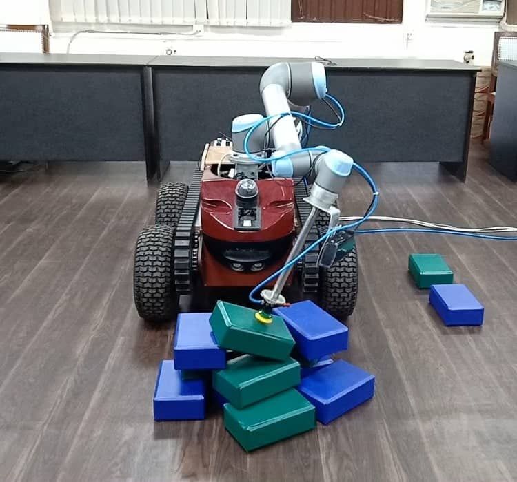
Kinect Sensor, is mounted on the manipulator. A suction-
based gripper is used for grasping. Robot Operating System
(ROS) is used to establish a communication link among the
Fig. 5: Network Predictions sensor, manipulator, and the gripper.
B. Overall Algorithmic Flow
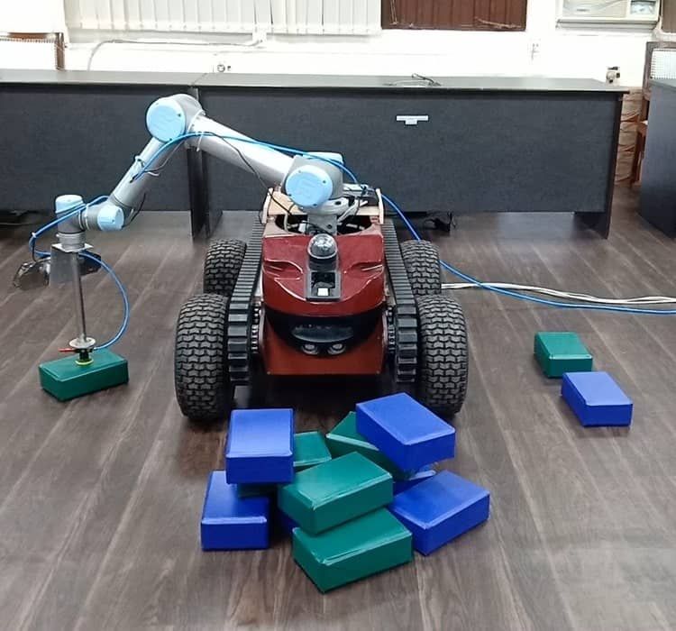
relative transformation to extract the complete brick pose. For
this task, we feed the current image (Fig. 6a) to the rotating For the experiment, we follow a simple pattern (or wall
box network. The region corresponding to the rotating box pattern) such that we place a blue brick on the previously
(Fig. 6b) is called the brick region, and the point cloud placed blue brick and a green brick over the previously
corresponding to the brick region is called the brick cloud. placed green brick and keep on placing the bricks up to
On the brick’s cloud, we apply the following steps: the height of 6 layers. The system needs to place the brick
correctly for wall construction, hence requiring the brick
• Apply RANSAC method for estimating a set of points
pose with high accuracy. Since in a dense clutter, network
(inliers) that fits a planar surface in the brick cloud data.
prediction for brick can include some portion of other bricks,
• Compute the centroid, major axis, and minor axis of
directly processing the box regions for pose can give a noisy
the inliers. Together these three pieces of information
or less reliable brick pose. For the safer side, we perform the
represent the pose of the planar surface. To estimate the
grasp operation with a noisy brick pose and place the brick in
surface ID, we follow the following steps.
a separate area and again estimate the pose of single isolated
• Using [24], extract all boundary points in the inliers,
brick.
which is marked in white color in Fig. 6d.
Fig. 7 refers to the sequence of steps executed to complete
• Apply RANSAC method for fitting the lines on the
a single phase of the wall construction task. In the first
boundary points which are shown pink in Fig. 6e.
stage, the Kinect sensor is positioned to have a clear view of
• Compute all corner points, which are the intersecting
the bricks clutter (Fig. 7a), and the current image is fed to
point of two or more lines.
the rotating bounding box network. We compute the planar
• Pair the corner points representing the same line [25],
surface and its pose (centroid, major-axis, and minor-axis)
and the distance between two corner points gives the
corresponding to each rotated box. We select the topmost
length of the edge.
pose from all the calculated poses, i.e., the pose at the top
• Since the brick dimensions are known in advance.
of the clutter. The required motion commands are generated
Hence the length of the edges can be used to identify
to reach the selected pose for brick grasping in clutter (Fig.
the surface, and we can use relative transformation to
7b).
compute the 6D pose of the brick, as shown in Fig. 6f.
The grasped brick is placed in a separate area (Fig. 7c),
and again the vision sensor is positioned in an appropriate
position to have a clear view of a single isolated brick
(Fig. 7d). At this instant, the current frame is fed to the
network, and the output of the network is a class label and
the bounding box parameters. The brick’s pose is estimated
and required motion commands are generated to grasp the
(a) Image (b) Rotating box (c) Point Cloud brick (Fig. 7e).
In the final stage, the sensor is positioned in an appropriate
position to have a view of the wall region (Fig. 7f). The
current frame is fed to the network. Using the estimated
bounding box, point cloud data, and grasped brick label
(previous step), the brick’s final pose is estimated, where
(d) Edges (e) Lines (f) 6D Pose the brick is to be placed to form a wall (Fig. 7g).
Fig. 6: Pose estimation pipeline C. Error Metrics
V. E XPERIMENTS AND R ESULT The system’s overall wall-building performance depends
entirely upon the performance of the visual perception sys-
A. Experimental Setup
tem, i.e., the accuracy of brick detection. Therefore, we
For experimental evaluation, we use our robotic plat- report the performance of the detection system in terms of
form setup, as shown in Fig. 1a. It consists of a UR5 precision (P ) and recall (R). We have defined P, C as:
robot manipulator with its controller box (internal computer)
mounted on a ROBOTNIK Guardian mobile base and a NO DB
P = , R= (1)
host PC (external computer). The UR5 robot manipulator TP TB
is a 6-DOF robotic arm designed to work safely alongside where,
humans. We use an eye-in-hand approach, i.e., the image N O Number of object pixels in the predicted box (ro-
acquisition hardware, which consists of RGB-D Microsoft tated / upright)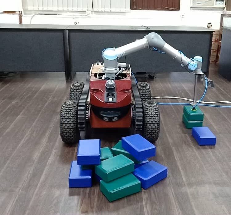
(a) (b) (c) (d) (e) (f) (g)
Fig. 7: Sequence of actions executed in order to carry out a single step of wall construction
TP Total number of object pixels in the predicted box
(rotated / upright)
DB Total number of detected bricks
TB Total number of the bricks in the ground truth. (a) (b) (c) (d)
D. Quantitative Analysis
We compare rotating box network with YOLO-v3 and
SSD-lite. For fair comparison, all models are trained by
choosing hyper-parameters as epoch = 60, mini − batch = (e) (f) (g) (h)
4, lr = 0.0001 except SSD-lite which has a learning rate
of 0.001. We use Adam optimizer to tune the parameters of
CNN. We divide the quantitative analysis in following two
cases:
1) Upright Bounding Box Prediction: In this case, we (i) (j) (k) (l)
report Mean Average Precision (mAP) score, P and R of
the proposed CNN model against SSD-lite and YOLO-v3
(Table-I). All the three models produces upright bounding
boxes.
TABLE I
(m) (n) (o) (p)
SSD-lite YOLO-v3 Proposed
P 0.608 0.580 0.638
R 0.98 0.84 0.84
mAP 0.834 0.827 0.811
2) Rotated Bounding Box Prediction: In this case, SSD- (q) (r) (s) (t)
lite and YOLO-v3 produce regular bounding boxes, while the
proposed CNN model produces rotated boxes. Since the mAP Fig. 8: From Column 1 to 4: YOLO-v3 predictions, SSD-lite
score of rotated boxes can not be compared directly with that predictions, Proposed Bounding box predictions, Rotating
of upright bounding boxes. Hence only P and R is reported box predictions.
(Table-II). The precision P for rotating boxes network is
significantly higher as compared to other networks, because
of the one additional degree of freedom (angle of boxes), the (Fig. 8p), both assign two different boxes for the two green
network predicts bounding boxes that can align more accu- bricks. Thus SSD-lite and our network have a higher recall.
rately as compared to constrained bounding boxes (straight However, in SSD-lite, two predicted bounding boxes have a
boxes), thus there will be less overlap between different significant overlap area, thus having lower precision than the
boxes and most of the region inside the bounding box rotating box network.
represents the same object which results in high precision.
F. Task Evaluation
TABLE II To evaluate the system’s performance, we repeat the task
SSD-lite YOLO-v3 Proposed of wall construction for 25 rounds. For each round, the
P 0.608 0.580 0.778 robotic system has to place the bricks up to the height of
R 0.98 0.84 0.999
6 layers, and the wall pattern will remain the same, i.e., the
blue brick on previously placed blue brick and green brick
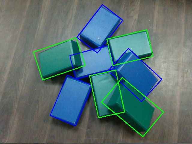
E. Qualitative Analysis on previously placed green brick. For the experiments, the
Predictions of all four networks under consideration are first layer of bricks is placed manually, and the system has
shown in Fig. 8. It can be noticed from Fig. 8m and 8o, two to place the rest of the bricks, i.e., 2 − 6 layers, according
green bricks present in the center of the frame are represented to the pattern. We count the number of bricks (or layers) for
by a single bounding box, thus decreasing the recall value each round the robotic system has successfully placed on
for Yolo-v3 and the proposed bounding box network. While the wall. In the experiments, we define the brick placement
SSD-lite (Fig. 8n) and the proposed rotating box network as successful if the distance between the centroid of the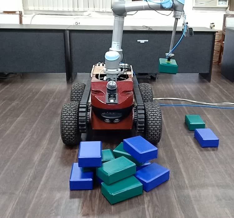
currently placed brick and the centroid of the manually                      [4] R. Girshick, J. Donahue, T. Darrell, and J. Malik, “Rich feature
placed brick, when projected on the ground plane is < 0.1m.                      hierarchies for accurate object detection and semantic segmentation,”
                                                                                 in Proceedings of the IEEE conference on computer vision and pattern
Further, the Euler angle difference between the calculated                       recognition, pp. 580–587, 2014.
pose of the currently placed brick and the manually placed                   [5] K. He, X. Zhang, S. Ren, and J. Sun, “Spatial pyramid pooling in deep
brick should be less than 15° for each axis. From our                            convolutional networks for visual recognition,” IEEE transactions on
                                                                                 pattern analysis and machine intelligence, vol. 37, no. 9, pp. 1904–
experiments, we observed that if none of the above criteria                      1916, 2015.
are satisfied, the wall becomes asymmetrical and collapses.                  [6] R. Girshick, “Fast r-cnn,” in Proceedings of the IEEE international
The Table-III shows the performance of the system for                            conference on computer vision, pp. 1440–1448, 2015.
                                                                             [7] S. Ren, K. He, R. Girshick, and J. Sun, “Faster r-cnn: Towards real-
25 rounds. The video link for the experiment is https:                           time object detection with region proposal networks,” in Advances in
//www.youtube.com/watch?v=FvsCv-Pt58c.                                           neural information processing systems, pp. 91–99, 2015.
                                                                             [8] S. Li, Z. Zhang, B. Li, and C. Li, “Multiscale rotated bounding
                  TABLE III: Task Evaluation                                     box-based deep learning method for detecting ship targets in remote
                                                                                 sensing images,” Sensors, vol. 18, no. 8, p. 2702, 2018.
                 layer-2    layer-3    layer-4   layer-5    layer-6          [9] K. He, G. Gkioxari, P. Dollár, and R. Girshick, “Mask r-cnn,” in
    Successful                                                                   Proceedings of the IEEE international conference on computer vision,
     rounds         25        25         22        19         17                 pp. 2961–2969, 2017.
    (max 25)                                                                [10] K. Simonyan and A. Zisserman, “Very deep convolutional networks
                                                                                 for large-scale image recognition,” arXiv preprint arXiv:1409.1556,
   From Table-III, we observed that the robotic system has                       2014.
                                                                            [11] K. He, X. Zhang, S. Ren, and J. Sun, “Deep residual learning for image
successfully placed layer-2 and layer-3 bricks in all 25                         recognition,” in Proceedings of the IEEE conference on computer
rounds. However, accuracy decreases with the upper layers.                       vision and pattern recognition, pp. 770–778, 2016.
This is because the new position of the brick on the wall                   [12] J. Redmon, S. Divvala, R. Girshick, and A. Farhadi, “You only look
                                                                                 once: Unified, real-time object detection,” in Proceedings of the IEEE
is estimated by calculating the previously placed brick pose.                    conference on computer vision and pattern recognition, pp. 779–788,
Thus, if there is a slight error in brick placement in the                       2016.
previous step, this error is transferred to the current step.               [13] W. Liu, D. Anguelov, D. Erhan, C. Szegedy, S. Reed, C.-Y. Fu,
                                                                                 and A. C. Berg, “Ssd: Single shot multibox detector,” in European
Thus, with higher layers, the error accumulates, resulting in                    conference on computer vision, pp. 21–37, Springer, 2016.
lower accuracy.                                                             [14] B. Tekin, S. N. Sinha, and P. Fua, “Real-time seamless single shot
                                                                                 6d object pose prediction,” in Proceedings of the IEEE Conference on
                                                                                 Computer Vision and Pattern Recognition, pp. 292–301, 2018.
                         VI. C ONCLUSION                                    [15] Y. He, W. Sun, H. Huang, J. Liu, H. Fan, and J. Sun, “Pvn3d: A deep
                                                                                 point-wise 3d keypoints voting network for 6dof pose estimation,”
   An end-to-end visual perception framework is proposed.                        in Proceedings of the IEEE/CVF conference on computer vision and
The framework consists of a CNN for predicting a rotated                         pattern recognition, pp. 11632–11641, 2020.
bounding box. The performance of the CNN detector has                       [16] R. B. Rusu, G. Bradski, R. Thibaux, and J. Hsu, “Fast 3d recognition
                                                                                 and pose using the viewpoint feature histogram,” in 2010 IEEE/RSJ
been demonstrated in various scenarios, which mainly in-                         International Conference on Intelligent Robots and Systems, pp. 2155–
clude isolated and dense clutter of bricks. The proposed CNN                     2162, IEEE, 2010.
module localizes the bricks in a clutter while simultaneously               [17] J. P. S. do Monte Lima and V. Teichrieb, “An efficient global
                                                                                 point cloud descriptor for object recognition and pose estimation,” in
handling multiple instances of the bricks. The detection is                      2016 29th SIBGRAPI Conference on Graphics, Patterns and Images
free of the anchor-box technique, which improves the timing                      (SIBGRAPI), pp. 56–63, IEEE, 2016.
performance of the detection module. In order to compare                    [18] B. Drost, M. Ulrich, N. Navab, and S. Ilic, “Model globally, match
                                                                                 locally: Efficient and robust 3d object recognition,” in 2010 IEEE com-
our method quantitatively with state-of-the-art models, we                       puter society conference on computer vision and pattern recognition,
reported Precision (P ), Recall (R), and mAP scores for                          pp. 998–1005, Ieee, 2010.
various test cases. We have compared the effectiveness of                   [19] S. Hinterstoisser, V. Lepetit, N. Rajkumar, and K. Konolige, “Going
                                                                                 further with point pair features,” in European conference on computer
rotating bounding box predictions against upright bounding                       vision, pp. 834–848, Springer, 2016.
box detection (YOLO-v3, SSD-Lite). The proposed scheme                      [20] P. J. Besl and N. D. McKay, “Method for registration of 3-d shapes,”
outperforms the upright bounding box detection. It implies                       in Sensor fusion IV: control paradigms and data structures, vol. 1611,
                                                                                 pp. 586–606, International Society for Optics and Photonics, 1992.
that rotating bounding boxes can align more accurately with                 [21] A. Segal, D. Haehnel, and S. Thrun, “Generalized-icp.,” in Robotics:
the object’s convex-hull and thereby reduce the overlap with                     science and systems, vol. 2, p. 435, Seattle, WA, 2009.
neighboring bounding boxes(if any). The framework has also                  [22] N. Bodla, B. Singh, R. Chellappa, and L. S. Davis, “Soft-nms–
                                                                                 improving object detection with one line of code,” in Proceedings of
been successfully deployed on a robotic system to construct                      the IEEE international conference on computer vision, pp. 5561–5569,
a wall from bricks in fully autonomous operation.                                2017.
                                                                            [23] A. Kumar and L. Behera, “Semi supervised deep quick instance
                                                                                 detection and segmentation,” in 2019 International Conference on
                           R EFERENCES                                           Robotics and Automation (ICRA), pp. 8325–8331, IEEE, 2019.
                                                                            [24] M. Vohra, R. Prakash, and L. Behera, “Real-time grasp pose estimation
[1] K. Asadi and K. Han, “Real-time image-to-bim registration using              for novel objects in densely cluttered environment,” in 2019 28th
    perspective alignment for automated construction monitoring,” in             IEEE International Conference on Robot and Human Interactive
    Construction Research Congress, vol. 2018, pp. 388–397, 2018.                Communication (RO-MAN), pp. 1–6, IEEE, 2019.
[2] S. Parkes, “Automated brick laying system and method of use thereof,”   [25] M. Vohra., R. Prakash., and L. Behera., “Edge and corner detection
    Jan. 31 2019. US Patent App. 16/047,143.                                     in unorganized point clouds for robotic pick and place applications,”
[3] R. Prakash, M. Vohra, and L. Behera, “Learning optimal parameterized         in Proceedings of the 18th International Conference on Informatics in
    policy for high level strategies in a game setting,” in 2019 28th            Control, Automation and Robotics - ICINCO,, pp. 245–253, INSTICC,
    IEEE International Conference on Robot and Human Interactive                 SciTePress, 2021.
    Communication (RO-MAN), pp. 1–6, IEEE, 2019.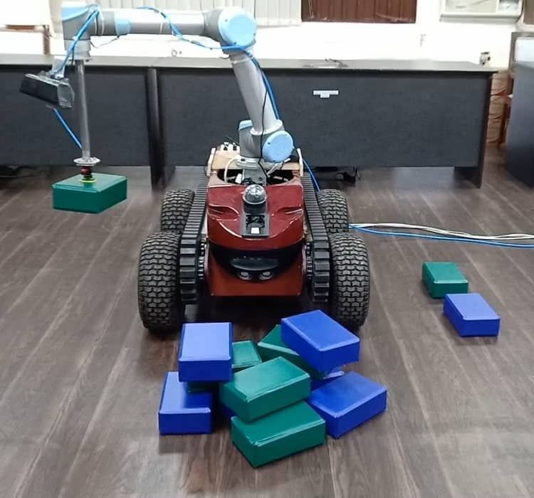
You can also read