SICAM Q100 Power Monitoring Device und Power Quality Recorder, Class A - Power Quality devices for all applications
←
→
Page content transcription
If your browser does not render page correctly, please read the page content below
Power Quality devices for all applications

SICAM Q100
Power Monitoring Device und Power Quality Recorder, Class A

                                              siemens.com/powerquality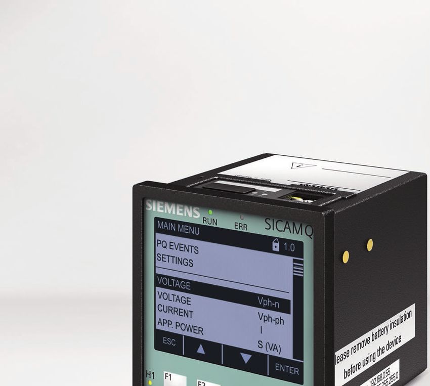
Products – SICAM Q100
    Contents

                                                          Page

     Description                                            2

     Function overview                                      4

     Data availability                                      6

     Power quality acquisition and recording                8

     Recorder types and evaluation                         10

     Parameterization, visualization, and evaluation       13

     Communication                                         15

     System overview                                       16

     Voltage quality measurements and operating
     measurement uncertainty                               17

     Measurements and operating measurement uncertainty    18

     Connection types and examples                         19

     Variants and dimensions                               21

     Technical data                                        23

     Technical data, selection and ordering data           27

1   SICAM – Power Quality and Measurements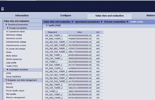
Products – SICAM Q100
                                                                                                                  Description

Universal unit for monitoring power quality and for
energy management
SICAM Q100 is a Class A multifunctional measuring device
for monitoring power quality according to the IEC 62586-1
(PQI-A-FI) product standard. It is used to acquire, visualize,
analyze, and transmit measured electrical variables such as
AC current, AC voltage, frequency, power, harmonics, etc.
The acquisition, processing and accuracy of measured variables
and events are performed according to the IEC 61000-4-30
Class A power quality measurement standard. Long-term data
and events are evaluated directly in the device and displayed
as a report in accordance with power quality standards (such
as EN 50160).
The measured variables can be output to a PC or control center
via one of the communication interfaces or shown on a display.
In addition to acquiring the power supply quality according
to Class A, SICAM Q100 also offers energy management
functions such as the acquisition of load profiles and the
relationship to different tariffs, as well as the Modbus Master
function for connecting RS485 submeters (for example, PAC)
and LV circuit breakers (such as 3WL).
                                                                  Fig. 1/33 SICAM Q100
Applications
SICAM Q100 is used in single-phase systems as well as three-      Benefits and key features
wire and four-wire systems (with neutral conductors).               Early detection of supply quality problems thanks to uninter-
This universal device is most valuable for applications where       rupted acquisition of important power parameters.
the uninterrupted acquisition of supply quality data (e. g.         Manufacturer-independent, comparable measured values
EN 50160) must guarantee fault-free operation of the loads/         for evaluating supply quality are obtained using standard-
consumers connected to the power supply system. In addition         ized measurement methods according to IEC 61000-4-30
to acquiring supply quality data, the unit can also be used for     Class A (0.1% accuracy).
the comprehensive acquisition of other measured electrical          Flexible “on-board” power quality logging according to
variables that are required by the particular application: as       EN 50160 performed directly via integrated a web server.
part of an automation solution in industrial plants, for energy     Power monitoring functions for power control and as a
management and building automation, in commercial applica-          prerequisite for energy management tasks such as
tions (assignment of cost centers), and for the comprehensive       identifying potential savings in the peak and base load
monitoring of important points in a power company’s network.        ranges and identifying unnecessary power consumption.
With its Master function, SICAM Q100 makes it possible to           Recording of the fourth current channel to acquire neutral
integrate and further process data from peripheral devices          conductor current data.
(for example, a power meter or LV circuit breaker).                 Highly precise measurements as part of energy manage-
Whether the need is for comprehensive supply quality monitor-       ment tasks, Class 0.2S according to IEC 62053-22 and
ing and logging or for energy management functions (for             ANSI C12.20 for obtaining power, reference, and energy
example, to reduce operating costs): SICAM Q100 is a key            measurements.
component in any power monitoring system.                           Modbus Gateway and Master functions for easily integrating
                                                                    and displaying RS485 device data (such as PAC3100, 3200,
                                                                    SICAM P50) via a Modbus TCP network.
                                                                    Easy operation via integrated web server for parameteriza-
                                                                    tion, diagnosis, evaluation, and reporting.
                                                                    Interoperability through the use of standard interfaces,
                                                                    protocols (IEC 61850, Modbus TCP), and data formats
                                                                    (PQDIF, Comtrade, and CSV).

                                                                                           SICAM – Power Quality and Measurements   2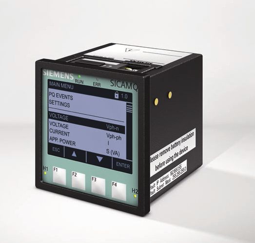
Products – SICAM Q100
    Description

    Voltage quality – application overview
    Voltage quality (also known as power quality) refers to various             example, damage to workpieces or tools, plant restarts, etc.
    characteristics in a power supply system. Voltage quality criteria          Data centers and “provider houses,” the number of which is
    are defined by a number of technical regulations, such as the               growing, are also concerned about their plants’ security of
    EN 50160 power quality standard. These criteria describe the                supply because voltage disturbances in these types of enter-
    main characteristics of voltage at customers’ power supply                  prises and operating areas can have serious consequences.
    terminals in public low-, medium-, and high-voltage systems.                Voltage measurements and evaluations can be used to
    Ultimately, however, quality is determined by the ability of                determine voltage quality.
    customer systems to correctly perform their tasks.                          As consumers’ awareness of energy efficiency grows, quality
    Most quality problems affect the ultimate consumer directly                 of supply becomes a major focus. So it is also in the interest
    or are perceived at this level. Today, production plants such as            of power utilities to monitor power quality, thus ensuring
    those in the paper and chemical industries are extraordinarily              proper and efficient operation and improving the system. A
    sensitive due to the wide use of microprocessor-supported                   high-quality, reliable power supply also means high customer
    controlling systems, information processing devices, and power              satisfaction.
    electronics devices. Temporary interruptions of supply and
    undervoltages can already result in high costs due to, for

                                                      System automation,             Key functions
                                                       SCADA, DMS, EMS,
                                                     e.g. SICAM PQS system             Evaluation of data from substations and distributed generation
                                                                                       EN 50160 voltage quality report
                                                            IEC 61850                  Event analysis
                                                                                       Load profile
                                                                                       Direction of power flow
                                                                                       Voltage, frequency, and harmonics profile
                                                                                       Limit value violations e-mail notification with SICAM PQS

                                                                          110 kV 20 kV
                                                                                          20 kV                           20 kV
          High-voltage /
         medium-voltage                                                                                                                   SICAM Q100
           switchgear                                                                                                                     P855 devices

         Medium-voltage /
           low-voltage

    Fig. 2/33 Application – Voltage quality on all voltage levels of the power supply system

3   SICAM – Power Quality and Measurements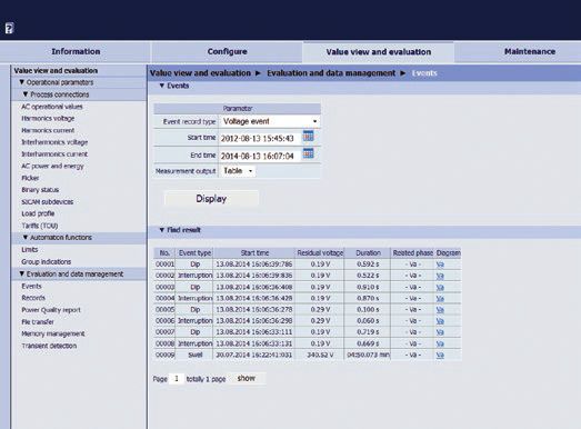
Products – SICAM Q100
Function overview
Monitoring System, Monitoring of current – main applications
e.g. Power Manager Power engineering (load profile, current monitoring,
and operating values)
Modbus TCP / EN 50160 voltage quality report and event analysis
web server Limit value violation
Warning indication and command
Notification
Distribution Recommended Measurements
Metering from Utility
Point of delivery Wtotal over all phases
Transformer G U U, I, S, cos phi all 3 Phases U G U U, I, P, W all 3 Phases
I Power Quality in all phases I I Power Factor
S S SICAM Q100
Q1 P
W all 3 Phases
PQ PQ
SICAM Q100
PQ
I all 3 Phases Special Loads U, I, THD,
S all 3 Phases Harmonics, Flicker
Special loads
Loads I all 3 Phases
UPS U
SICAM P PQ
PQ USV SICAM P855
Main distribution
board
I
ILN I all 3 Phases
Subdistribution ISumme SICAM P
W all 3 Phases
board W
I
I I all 3 Phases I all 3 Phases
W W all 3 Phases W, W all 3 Phases
SL L L SL Harmonics
Special loads Loads SICAM P SICAM P
Fig. 3/33 Application – Voltage quality and power monitoring for industry, buildings, and data centers
Device description Communication
SICAM Q100 is a multifunctional measuring device used to SICAM Q100 has one Ethernet interface and one optional elec-
acquire, calculate, record, analyze, display, and transmit trical RS485 interface. Device parameterization, the transmis-
measured electrical variables. Its key features are: sion of measured data, counts, and messages, as well as time
Power Monitoring and Power Quality Recorder, including synchronization (via NTP) are supported via Ethernet. The HTTP,
Measurand Recorder for measurement accuracy according Modbus TCP, and IEC 61850 Server communication protocols
to IEC 61000-4-30, Class A can be used. The integrated Ethernet switch makes it possible
Web server for parameterization, visualization, and data to connect additional devices (such as subordinate SICAM
management devices) via a Y-cable and integrate them into an existing
Galvanically separated voltage measurement inputs network using IEC 61850 or another Ethernet protocol.
Transmission of measured values via various communication The optional RS485 interface supports the Modbus RTU
protocols communication protocol for the purpose of transmitting
4 inputs for AC voltage measurements measured data, counts, load profiles, and messages, and for
4 inputs for AC current measurements time synchronization.
2 binary inputs, for example for load profile synchronization
pulses or external triggers Time synchronization
2 binary outputs SICAM Q100 must have an unambiguous time basis during
Binary expansion (up to 12 inputs and 12 outputs) using operation to acquire time-relevant data such as voltage events.
SICAM I/O Unit peripheral devices This guarantees that connected peripheral devices have a
uniform time basis for all measured data.
SICAM – Power Quality and Measurements 4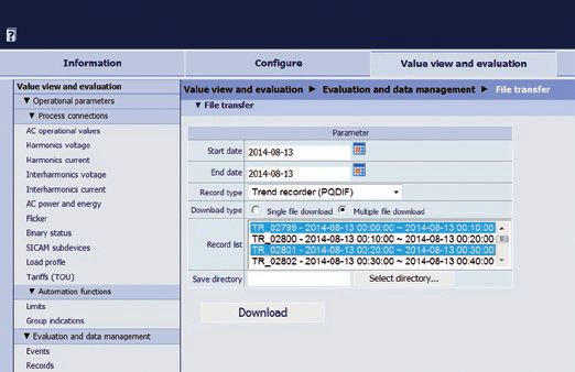
Products – SICAM Q100
    Function overview

    The following types of time synchronization can be performed:      Load profile recording: The load profile reflects the
      External time synchronization via Ethernet NTP (preferred)       variations in electrical power over time and thus documents
      External time synchronization via field bus using the            the distribution of power fluctuations and peaks. Two
      Modbus RTU communication protocol                                methods of load profile recording are supported: the fixed
      Internal time synchronization via RTC (if external time          block method and the rolling block method.
      synchronization is not possible)                               The device has a 2-GB memory for logging the recorder data.

    Continuous measured value acquisition:                           Parameterization
      Alternating voltage U                                          Parameterization is performed from a connected PC using an
      Alternating current I                                          integrated web browser with HTML pages. Selected param-
                                                                     eters can also be configured using the function keys on the
      Power frequency f (fundamental component)
                                                                     front of the device.
      Active power P (accuracy Class 0.2S; ANSI C12.20 Class 2
      and Class 10)                                                  Evaluations
      Reactive power Q                                               Power quality values and other events are displayed directly
      Apparent power S                                               via a web browser with HTML pages. The following evaluations
                                                                     can be used:
      Power measurements W
                                                                        Operational measured values and messages from SICAM
      Active power factor cos phi                                       Q100 and from the relevant Modbus slave device displayed
      Measurements up to the 63rd harmonics order                       via HTML and on the display
      Interharmonics of voltage and current                             Event evaluations und power quality recordings as well as
                                                                        mean values displayed in tables or graphs
      Flicker according to IEC 61000-4-15
                                                                        Power Quality Reports generated according to the EN 50160
                                                                        standard
    Event-specific measured value acquisition:                          Logging of transient data
      Min./max./mean values
      Recording of events such as voltage dips, overvoltages,        Data export
      interruptions                                                  Recorded data can be exported in the following standard
      Limit value violations                                         formats:
      Acquisition of load profiles                                      CSV data
      Transient recording                                               PQDIF data – IEEE1159.3: PQDIF for PQ recordings
                                                                        (events, measurements, logs)
    Power management                                                    COMTRADE data – IEC 60255-24/IEEE Std C37.111:
    As part of power management, SICAM Q100 uses the fixed              Electrical relay – Part 24: Common format for transient
    block and rolling block methods to acquire load profiles with       data exchange (COMTRADE) for power systems
    all characteristics. Power data is acquired through up to four
    different tariff ranges (TOU = time of use); the switchover is   Automation functions
    via external or internal trigger.                                Upper and lower limit values can be parameterized for up to
                                                                     16 measured values. Warning indications can be output if
    Measured value acquisition via recorders                         these limits are exceeded. Up to four limit value violations
    Different recorders can record measured values, events, and      are output to the device via the two binary outputs as well as
    load profiles at parameterizable intervals. The following        the H1 and H2 LEDs. In addition, all 16 limit value violations
    recorder types can be used:                                      can be sent to peripheral devices via Ethernet.
       Measurand recorder: Records mean value measured
       variables according to IEC 61000-4-30 (such as frequency,     Special feature
       voltage, etc.) and logs relevant data (such as currents,      Embedded Ethernet switch for the quick and economical
       power, etc.) over a parameterized time period.                integration of additional Ethernet-compatible devices
      Trend recorder: Long-term recording and monitoring of          without having to add a supplemental network switch.
      voltage changes over a parameterizable time period,
      including programmable tolerance ranges; effective values
      with up to 1/2 period resolution.
      Fault recorder: Records measured values for current and
      voltage using parameterizable triggers.
      Event recorder: With 256 sampled values per period,
      records events in terms of voltage, frequency, and voltage
      unbalances.

5   SICAM – Power Quality and Measurements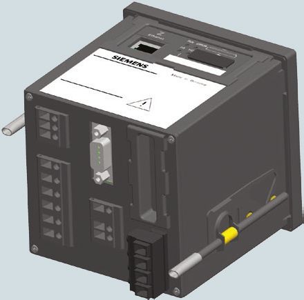
Products – SICAM Q100
Data availability
Data availability
Event analysis Trend recorder
Operational measured COMTRADE Measurand recorder
information (1/2 period effective
Data values
(dips, overvoltages,
fault recorder
value, event recording) –
(30 s, 60 s, 10 min,
(10/12 periods) file 15 min, 30 min, 1 h, 2 h)
interruptions) COMTRADE file
IEC 61850 protocol
Modbus TCP, Modbus RTU, Modbus TCP, IEC 61850,
IEC 61850, (m PQDIF format),
Interface IEC 61850, HTML and IEC 61850, HTML and
export
HTML visualization,
HTML visualization,
display display export as PQDIF
export as PQDIF, CSV
Mean Min. Max.
Type Values Values COMTRADE PQDIF values values values
AC voltage UL1, L2, L3 x x1 x x x x x
1
UL12, 23, 31 x x x x x x x
UN x x x x
Utot x x x x
Uunbal x x x x
AC current IL1, L2, L3 x x x x x
I0 x x x x
Itot x x x x
Iunbal x x x x
Active power cos φ (L1), (L2), (L3) x x x x
factor
cos φ x x x x
Power factor PFL1, PFL2, PFL3 x x x x
PF x x x x
Phase angle L1, φ L2, φ L3 x x x x
x x x x
Frequency f (power freq.) x
10 s freq (10 freq.) x2 x2 x2
Harmonics,
H_UL1-x, UL2-x, UL3-x x5 x – x
voltage, amount
Harmonics, H_IL1-x, H_IL2-x,
x5 x6 – x6
current, amount H_IL3-x
THD_UL1, THD_UL2,
THD, voltage x x x x
THD_UL3
THD_IL1, THD_IL2,
THD, current x x x x
THD_IL3
Voltage HI_Va-y, HI_Vb-y,
x6 x6 – x6
interharmonics HI_Vc-y
Current
HI_Ia-y, HI_Ib-y, HI_Ib-y x6 x6 – x6
interharmonics
Flicker (short) Pst1, Pst2, Pst3 x3 x3 x3
Flicker (long) Plt1, Plt2, Plt3 x4 x4 x4
Active power factor PL1, PL2, PL3 x x x x
P x x x x
Reactive power QL1, QL2, QL3 x x x x
Q x x x x
Apparent power SL1, SL2, SL3 x x x x
S x x x x
Active energy – WPL1, WPL2,
X – Cumulated
supply WPL3_Supply
WP_Supply X – Cumulated
Table 1/7 Data availability
SICAM – Power Quality and Measurements 6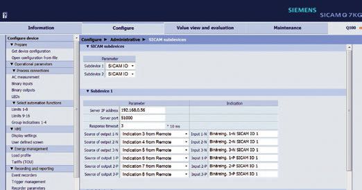
Products – SICAM Q100
    Data availability

                                                                                Event analysis                            Trend recorder
                                                    Operational measured                             COMTRADE                                       Measurand recorder
                                                                                 information                           (1 2 period effective
                              Data                         values
                                                                             (dips, overvoltages,
                                                                                                    fault recorder
                                                                                                                     value, event recording) –
                                                                                                                                                    (30 s, 60 s, 10 min,
                                                      (10 12 periods)                                     file                                    15 min, 30 min, 1 h, 2 h)
                                                                                interruptions)                            COMTRADE file

                                                                                                                                                     IEC 61850 protocol
                                                   Modbus TCP, Modbus RTU,        Modbus TCP,                             IEC 61850,
                                                                                                     IEC 61850,                                       (m PQDIF format),
                              Interface             IEC 61850, HTML and      IEC 61850, HTML and
                                                                                                       export
                                                                                                                       HTML visualization,
                                                                                                                                                     HTML visualization,
                                                           display                  display                             export as PQDIF
                                                                                                                                                    export as PQDIF, CSV

                                                                                                                                                 Mean       Min.       Max.
                              Type                         Values                  Values            COMTRADE                 PQDIF              values    values     values

        Active energy –       WPL1, WPL2,
                                                      X – Cumulated
        reference             WPL3_Reference
                              WP_Reference            X – Cumulated
        Reactive energy –     WQL1, WQL2,
                                                        Cumulated
        inductive             WQL3_Inductive
                              WQ_Inductive            X – Cumulated
        Reactive energy –     WQL1, WQL2,
                                                      X – Cumulated
        capacitive            WQL3_Capacitive
                              WQ_Capacitive           X – Cumulated
        Apparent energy       WSL1, WSL2, WSL3        X – Cumulated
                              WS                      X – Cumulated
        Tariff (TOU) –        WP_SUP_Tariff_1-4,      X – Cumulated
        power values –        WP_DMD_Tariff_1-4,
        Tariff 1 to 4         WQ_IND_POS_Tar-
                              iff_1-4,
                              WQ_CAP_NEG_Tar-
                              iff_1-4, WQ_IND_
                              NEG_Tariff_1-4,
                              WQ_CAP_POS_Tar-
                              iff_1-4,
                              WQ_IND-Tariff_1-4,
                              WQ_CAP-Tariff_1-4,
                              WS_Tariff_1-4
        Load profile data     PRef, PSupply,            Last interval
                                                                                                                                                  x7         x7         x7
                              QRef, QSupply, S           completed

    Table 1/7     Data availability

    1                                                                               7
      Event information according to EN 50160, e.g. voltage dip, overvoltage,           – The load profile data for the current and most recently completed
      interruption.                                                                       periods is output via the communication interfaces.
    2
      Frequency is permanently defined with a 10 second mean value record-              – Data can be transmitted via the Modbus TCP, Modbus RTU Master,
      ing.                                                                                and IEC 61850 communication protocols.
    3
      IEC 61000-4-15: Flicker Pst is permanently defined with a 10-minute               – The load profile data can be displayed in the user interface or down-
      recording.                                                                          loaded in CSV format. The load profile data does not appear on the
    4
      Flicker Plt is permanently defined with a 2-hour recording.                         display.
    5
      Available as of 1st to 63rd order.                                                – Load profile data mean values can be calculated from cumulated
    6
      Available as of 1st to 49th order.                                                  power or arithmetic power demand.

    To learn more about data availability and measured variables, refer to
    the SICAM Q100, 7KG95xx System Manual.

7       SICAM – Power Quality and Measurements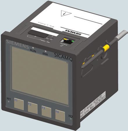
Products – SICAM Q100
                                                                                            Power quality acquisition and recording

Functions of the IEC 61000-4-30 Ed. 2 measurement system          Voltage events – interruption, voltage dip, overvoltage,
SICAM Q100 devices serve to measure voltage quality accord-       and transients
ing to IEC 61000-4-30 Ed. 2 and to perform other measure-         The basic measurement of the effective value Ueff of a voltage
ments in single-phase and multi-phase supply systems. The         event determines the effective value U eff (1/2) for each
measurement system is implemented according to Class A,           individual measuring channel. The limit value for voltage,
meaning that the functional scope, measuring ranges, and          hysteresis, and duration (t) characterizes one voltage event
accuracy are those of Class A measuring devices. The basic        for each individual measuring channel.
measuring interval for determining the values of mains voltage,   Mains voltage unbalance: Determined on the basis of the
mains voltage harmonics, and mains voltage unbalance is a         balanced component method. In the case of unbalance, both
10-period interval for 50-Hz supply systems and a 12-period       the positive-sequence component U1 and the negative-
interval for 60-Hz supply systems. The10/12-period interval       sequence component U2 are determined.
values are aggregated over additional time intervals.             Mains voltage harmonics: Uninterrupted 10/12-period
                                                                  measurement of a harmonic subgroup U sg,n according to
10-minute interval                                                IEC 61000-4-7. The total distortion is calculated as the
The value aggregated in a 10-minute interval is stamped with      subgroup total distortion (THDS) according to IEC 61000-4-7.
the absolute time (e.g. 01:10:00). The time is indicated at the   Measurements are performed up to the 63rd harmonics order
end of the aggregation interval. The values for the 10-minute     and recorded up to the 50th harmonics order.
interval are calculated without interruption from 10/12-period
intervals.                                                         V

                                                                       70

                                                                       60
Flagging concept                                                       50

During voltage dips, overvoltages, and interruptions, the              40

measurement method may supply implausible data for other               30

                                                                       20
measured values (such as frequency measurements or voltage
                                                                       10
harmonics). The flagging concept prevents individual events            0

from being accounted for multiple times by different measured          -10

variables (e.g. a dip simultaneously recorded as dip and               -20

frequency change).                                                     -30

                                                                       -40

                                                                       -50
Measurements for evaluating voltage quality                            -60

Mains voltage level: This measurement determines the                   -70

effective value of mains voltage over a 10-period interval for               44.85                                                  44.90                                                   44.95   s
                                                                                 15.6.10,     16:47
50-Hz supply systems and over a 12-period interval for 60-Hz
                                                                        Uoff n                                    Uoff n+4                                    Uoff n+8
supply systems. All 10/12-period intervals are detected                          Uoff n+1                                    Uoff n+5                                    Uoff n+9

without interruption or overlapping.                                                        Uoff n+2

                                                                                                       Uoff n+3
                                                                                                                                        Uoff n+6

                                                                                                                                                   Uoff n+7
                                                                                                                                                                                    Uoff n+10

                                                                        Ueff (1 / 2):   Effective value for a period, synchronized to the zero passage of the fundamental component,
                                                                                        updated after every half period.
                                                                                        This value is used only to detect voltage dips, swells and interruptions.

                                                                  Fig. 4 33 Representation of the 1/2 cycle RMS measurement method,
                                                                            e.g. for a voltage dip

                                                                                                                                 SICAM – Power Quality and Measurements                                 8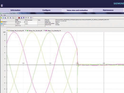
Products – SICAM Q100
    Power quality acquisition and recording

    Flicker: Uninterrupted recording according to IEC 61000-4-15.
    The following measurements are performed simultaneously
                                                                           Voltage
    for all three-phase voltages: instantaneous flicker Pinst (10/12
                                                                                                                                                 Highest voltage which can be measured with internal ADC
    measurement interval), short-term flicker strength Pst (10 min),                                                                                                               Transient reference level
    and long-term flicker strength Plt (2 h).                                                                                               Transient Off Detection Level = - 8% Transient reference level
    Transient recording: SICAM Q100 records temporary overvol-
    tages as transients if the instantaneous value of the primary
    rated voltage exceeds the parameterized reference value at                                                                                                                                                 Time
    multiple sampling times. SICAM Q100 records the following
    data and values during transient analysis and displays them
    in the transient list window:                                                                                        Zo
                                                                                                                           om
       Number of events
       Transient’s start time (timestamp with date and time)
       Affected phase (a, b, c)
                                                                                                                                                                                   Detected transient duration
       Transient duration
       Relative value (in %) up to 200% of the primary rated               Voltage                                                                                                  Real transient duration

       voltage: If the primary rated voltage is exceeded by more
       than 200%, the analysis will show only > 200%.
                                                                                                                                         Measured
                                                                                                                                          sample

                                                                                                              Sample time
                                                                                                               resolution

                                                                       0                                                                                                                                    Time

                                                                                                                                                Detected
                                                                                                                                              time stamp

                                                                        A transient will be detected if the instantanious value of the voltage (measured as sample) is higher than a given voltage reference level.

                                                                       Fig. 5/33 Representation of the measurement system concept,
                                                                                 e.g. when a transient is detected

9   SICAM – Power Quality and Measurements
Products – SICAM Q100
Recorder types and evaluation
Recorder functionality and applications
In addition to standard measured value acquisition, SICAM Q100 quality, as well as power management data for evaluating the
offers various recorders for monitoring and analyzing power load profile.
Recording Measured variables Storage interval / storage method Application
Measurand recorder Frequency 10 s (permanently set)
Mains voltage level
Mains voltage unbalance Long-term monitoring of
mean values, e.g. to evaluate
Mains voltage harmonics 10 min power quality according to
and interharmonics (30 s, 1 min, 10 min, 15 min, 30 min, 1 h, 2 h) EN 50160
Additional data (e.g. power
values, min/max values, etc.)
Monitoring of power quality
Flicker Pst determined over 10 min.; Plt over 2 h (12 Pst values)
according to IEC 61000-4-15
Event recorder Voltage dips
Residual voltage Urms (1/2) and timestamp (duration) Classification of voltage
Voltage interruptions
and frequency events,
e.g. according to EN 50160,
Voltage swells Max. overvoltage Urms (1/2) and timestamp (duration) ITIC curve
Trend recorder Urms (1/2) period For measured value changes (as percentage or absolute) Long-term monitoring and re-
and cyclic (time interval) cording of voltage Urms (1/2)
period for precise visualiza-
tion and subsequent analysis
of voltage events according
to power quality grid codes
Fault recorder Voltages, currents Voltage/current fluctuation trigger, acquisition of Sampled values (fault record)
sampled values (max. 3 s) recording to determine and
analyze causes of power
quality problems
Load profile recording Load profile Fixed block or rolling block method Determination of load profile
for power supply and con-
sumption
Table 2/7 Recorders and applications
SICAM – Power Quality and Measurements 10Products – SICAM Q100
Recorder types and evaluation
Measurand recorder Fault recorder
The measurand recorder records measured values for deter- The fault recorder records 2560 sampled values per 10/12
mining power quality as well as various other measurements period in programmable time units. The fault recorder
(for example, minimum/maximum values). Recording of the functionality can be activated for the voltage and current
following measured values can be parameterized in the user measured variables. For event analysis, a pretrigger time
interface: (pretrigger ratio in %) can be set, which allows the history
PQ measurements for determining power quality of the measured value to be analyzed prior to the fault’s
Averaging intervals for frequency (permanently set to 10 s) inception.
Averaging intervals for voltage, voltage unbalance, harmon-
ics, and interharmonics (30 s, 60 s, 10 min, 15 min, 30 min,
1 h, 2 h)
Flicker: Short-term flicker strength Pst (10 min) and
long-term flicker strength Plt (2 h)
Additional data: Current, current unbalance, active power,
apparent power, reactive power, THD of voltage, THD of
current, power factor, active power factor, phase angle,
energy values
Recording of minimum values (mean values) and recording
of maximum values (mean values)
The measuring interval can be set in increments ranging from
30 seconds to 2 hours. The interval for frequency measurement
is permanently set to 10 seconds.
Trend recorder
The trend recorder guarantees the continuous recording and
long-term monitoring of the Ueff (1/2) voltage. If the measured Fig. 7/33 Fault record in COMTRADE view using COMTRADE Viewer
variable changes over the effective value last detected during software and SIGRA plug-in
the parameterized measuring interval, exceeding or falling
below the set tolerance range, this new effective value is Load profile recording
recorded. The load profile reflects system behavior and documents the
distribution of power fluctuations and peaks. The recordings
Event recorder help to identify potential savings in the peak and base load
The event recorder records PQ events only (voltage, frequency, ranges. The appropriate recording and visualization of power
voltage unbalances). flows in the system permits a transparent analysis of the
energy flow, making it possible to optimally configure the
Udin process in terms of energy. The measured load profile data
Swell thus obtained permits a preliminary evaluation of existing
110
Hysteresis savings potential while also serving as a basis for intelligent,
(2%)
108 efficient power management.
Dip
100 •Power
•Day 1: 15.6 kW
•New Peak Demand
•Peak Demand •695 kW@ 13:40
92 Hysteresis •780 kW@8:30
Demand ‒ kW
90 (2%) 600
500
400
300
200
Event Event Event Event t
start stop start stop 100
0:00
1:30
3:00
4:30
6:00
7:30
9:00
10:30
12:00
13:30
15:00
16:30
18:00
19:30
21:00
22:30
24:00
Fig. 8/33 Load profile
Event Event t
duration duration
Fig. 6/33 Recording by the event recorder: overvoltages and undervoltages
11 SICAM – Power Quality and MeasurementsProducts – SICAM Q100
Recorder types and evaluation
SICAM Q100 supports two load profile recording methods: The load profile data is stored in a ring buffer with up to 4000
fixed block and rolling block. data records. Each new data record overwrites the oldest
Fixed Block: The default setting is a 15-minute measuring record. Each data record contains the power demand values,
period; the number of subperiods is set to 1. At the end of minimum/maximum values, a timestamp, and the status
each measuring period, the load profile data is calculated, information for a completed subperiod.
stored in the ring buffer and, if necessary, forwarded or
displayed on the user interface.
Rolling Block: With this method, a measuring period comprises
2 to 5 subperiods, depending on parameterization. The
duration of a measuring period is based on the number of
subperiods and the programmed duration of the subperiods.
The figure below shows the sequence of measuring periods
during load profile recording:
Measuring
period
3 Time at which the load profile Fig. 11/33 Load profile
data was recorded for the
completed measuring period
Historic load profile data
2 SICAM Q100 records the following historic measured values:
Arithmetic
1 Measure- Cumulated Maximum Minimum
power demand
ment power values values values
Duration of
values
measuring period
PImport x x
t [min]
±x ±x
PExport x x
0 15 20 45
QImport x x
Fig. 9/33 Load profile recording using the fixed block method ±x ±x
QExport x x
Measuring
period Example: S x x x x
A measuring period comprises
5 3 subperiods (SP with a duration SP SP SP
of 15 min each
Table 3/7 Historic load profile data
4 SP SP SP
Tariffs
SICAM Q100 supports up to four power meter tariffs for supplied
3 SP SP SP
or consumed active, reactive, and apparent energy. If the
tariffs are changed via binary inputs, up to 2 tariffs can be
2 SP SP SP
set. If tariff change is controlled, up to 4 tariffs can be set.
Calculation/recording of load
profile data from the 3 subperiods of The tariff is changed via external interfaces. A tariff time
the completed measuring period
1 SP SP SP change is possible only from a subordinate system.
Recording of load profile data
for the completed subperiod
t [min]
0 15 30 45 60 75 90 105
Fig. 10/33 Sequence of measuring periods for recording the load profile
using the rolling block method
The load profile is stored in the device’s ring buffer, is available
via the communication interfaces, and can be output as a CSV
file. Load profile recording can be synchronized or unsynchro-
nized. Synchronization is via an external or internal trigger.
The arithmetic power demand values and extreme values for
each subperiod are stored in the ring buffer. The cumulated
power values can be retrieved via the communication
interfaces or the user interface.
Fig. 12/33 Tariff analysis
SICAM – Power Quality and Measurements 12Products – SICAM Q100
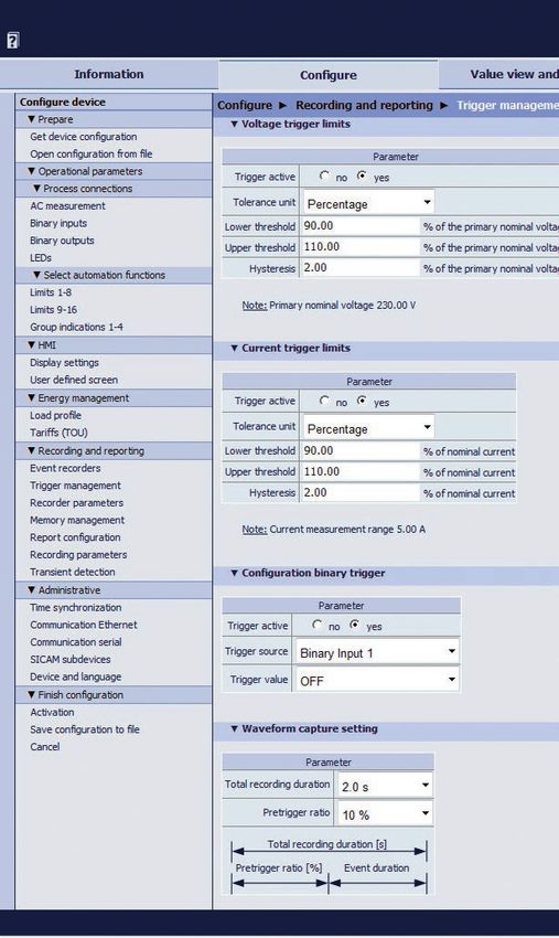
Parameterization, visualization, and evaluation
Device parameterization Visualization of values
SICAM Q100 devices are parameterized from a connected PC Depending on which operating parameters are selected, the
using the web browser integrated in the device. input/output window displays either the measured values in the
corresponding unit of measure or a tabular list that is updated
every 5 seconds.
Operational measured values
Voltage harmonics
Current harmonics
Interharmonics
Power and energy
Binary outputs
Limit values
Group indications
Flicker
Fig. 14/33 HTML display of harmonics
Voltage quality data
With SICAM Q100, the evaluation of recorded voltage events
(such as overvoltages, undervoltages, interruptions, etc.),
the generation of the PQ report according to EN 50160, data
transmission, and memory management are performed
directly in the device via HTML. A calendar function is used
to set the start and end times for the PQ report. The report
can be generated, printed, saved, and edited from the SICAM
Q100 HTML page.
Fig. 13/33 Configure tab, Trigger Management Input/Output window
13 SICAM – Power Quality and MeasurementsProducts – SICAM Q100
Parameterization, visualization, and evaluation
Configuration of power quality reports
The report configuration function can be used to set PQ
threshold values. Threshold values can be adapted to the
installation environment and various settings can be entered,
for example, to generate standardized reports according to
EN 50160 NS&MS or EN 50160 HS, or to generate user-de-
fined reports.
Fig. 15/33 Evaluation of voltage events Fig. 17/33 Measured Value Display and Analysis tab, “Events” Input/Out -
put window, voltage events
Recordings
Data transmission and download
With support from COMTRADE Viewer and the SIGRA plug-in,
Via IEC 61850, stored data from SICAM Q100 can be transmit-
SICAM Q100 can display the following recordings:
ted from the 2-GB memory, exported, or downloaded manually
Measurements for visualizing mean, minimum, and
via HTTP. The following data formats are supported:
maximum values in tables or graphs.
Measurements: PQDIF and CSV files
Trend recordings with resolution up to 1/2 period for
Fault recordings: COMTRADE files
visualizing voltage quality events.
Trend recordings: PQDIF files
Fault recordings of triggered voltages and currents.
Selected data can be flexibly downloaded using the calendar
The signals can be downloaded and then displayed on a
function.
PC using COMTRADE Viewer.
Fig. 16/33 Analysis of voltage events
Fig. 18/33 Data transmission and down
SICAM – Power Quality and Measurements 14Products – SICAM Q100
Communication
SICAM Q100 has an Ethernet interface and an optional
electrical RS485 interface. Device parameterization, trans-
mission of measured data, counts, and messages, as well as
time synchronization via NTP are supported via Ethernet.
The HTTP, Modbus TCP, and IEC 61850 Server communication
protocols can be used. The integrated Ethernet switch makes
it possible to connect additional devices (such as subordinate
SICAM devices) via a Y-cable and integrate them into an existing
network using IEC 61850 or another Ethernet protocol.
The optional RS485 interface supports the Modbus RTU commu-
nication protocol for the purpose of transmitting measured
data, counts, load profiles, and messages, and for time
synchronization.
Ethernet
Ethernet 100 Base-T with RJ45 connector
Integrated 2-port Ethernet switch with external cable switch
(for configuring line topologies with Ethernet and for
reducing costs for external Ethernet switches)
Serial
RS485 half-duplex with D-SUB connector
Support for various baud rates (1200 – 115,200 bit/s) and
parities (even/odd/none)
Data transmission protocols and functions
Modbus TCP (server) with up to 4 connections/Modbus
RTU Slave
Modbus RTU Master
Modbus TCP/RTU Gateway
SICAM I/O sub-devices UDP connection (2)
IEC 61850 (server) with up to six connections
NTP client (redundant), SNMP (server), HTTP (server)
15 SICAM – Power Quality and MeasurementsProducts – SICAM Q100
System overview
When SICAM Q100 is used as a stand-alone analyzer, data Application 1: The device is installed as a standalone device
and information can be accessed directly via HTML pages, for uninterrupted recording of all relevant parameters relating
displayed, and flagged. Other export functions such as PQDIF, to power quality, event analysis, and power management.
CSV, and COMTRADE are available directly from the device.
Additional programs such as SIGRA and COMTRADE Viewer
Application 2: In addition to Application 1, the device provides
binary expansions using up to two SICAM I/O Unit devices for
1
can be used to further analyze fault records. flexible status monitoring and external trigger functions.
SICAM Q100 is able to communicate flexibly with automation Application 3: SICAM Q100 uses the RS485 interface to
systems and evaluation stations via standard protocols such implement the Modbus Master and Modbus Gateway functions.
as IEC 61850 and Modbus TCP. With IEC 61850 Ed. 2, historical Connected and parameterized SICAM sub-devices output
data such as power quality and event recordings can be indications via their binary inputs and outputs.
transmitted to the SICAM PQS system in standard data formats
such as PQDIF and COMTRADE.
In addition, Modbus TCP can be used to monitor all device
operating parameters, protocols, and indications, as well as
information on voltage events. 2
The integrated Ethernet switch permits the integration of
additional devices via a Y-cable. An external Ethernet switch
can also be used to expand the I/O functions – for example, to
connect up to two subordinate SICAM I/O Unit 7XV5673
devices.
Via the optional RS485 interface, SICAM Q100 also provides
Modbus Gateway and a Master functions. The Gateway 3
functionality permits the quick and easy integration of other
RS485 devices – such as SENTRON PAC 3x00/4200, SICAM Fig. 19/33 Indications from SICAM sub-devices
P50, and 3VL/3WL low-voltage circuit breakers – into the
Modbus TCP or IEC 61850 network.
The Modbus Master function makes it possible to view and
monitor data from up to 8 of the above-mentioned devices on
the display or via HTML page.
Comprehensive web server
Power Manager
Evaluation station, functionality
SICAM PQS
(planned) SCADA + • Parameterization
+
5
PQ Analyzer • Value display
Web server
• Analysis
• Reporting
• CSV, PQDIF, and COMTRADE export
Automatic data transmission via
IEC 61850 Ed. 2 to SICAM PQS and
PQ Analyzer for complete system
evaluation
6
Power Manager via Modbus to
manage and monitor power
SICAM Q100
RS485 (up to 8 devices)
SICAM Q100 SICAM Q100
1st application
(measuring device only)
SICAM I/O Unit: ≥12 I and 12 O
2nd application
7
SICAM Q100 with expanded I/O functionality
PACs3x00, 3WL/VL circuit-breaker
and 2 x SICAM I/O Units
3rd application
With Modbus Gateway and Master functions for
integrating Modbus RTU devices into TCP networks as
visualization of RS485 devices
Fig. 20/33 Sample application
8
SICAM – Power Quality and Measurements 16Products – SICAM Q100
Voltage quality measurements and operating measurement uncertainty
Voltage quality measurements and operating measurement
uncertainty according to the IEC 62586-1, Class A product
standard, and the power quality standards IEC 61000-4-30,
Ed. 2, IEC 61000-4-7, and IEC 61000-4-15
Parameter Unit Uncertainty Measuring range Comments
Frequency Hz ± 10 MHz 42.5~57.5 Hz (50 Hz) Mains voltage level must be > 2 V!
51~69 Hz (60 Hz)
Supply level U ± 0.1% of Udin 10 %~150 % Udin Voltage UL-N/PE (star connection)
– AC 57.73 V to 400 V (autorange)
– up to AC 230 V: up to 200% measuring range
– > AC 230 V to 400 V: up to 200% measuring
range and 15% overvoltage
UL conditions:
– up to AC 170 V: up to 200% measuring range
– > AC 170 V to 300 V: up to 200% measuring
range and 15% overvoltage
Voltage UL-L (delta connection)
– AC 100 V to 690 V (autorange)
– up to AC 400 V: 200% measuring range
– > AC 400 V to 690 V: up to 200% measuring
range and 15% overvoltage
UL conditions:
– up to AC 290 V: up to 200% measuring range
– > AC 290 V to 520 V: up to 200% measuring
range and 15% overvoltage
Flicker – ± 5% 0.2~10.0 Pst Accuracy Pinst: ± 8%
Dips, overvoltage U, s Amplitude ± 0.2% Udin NA
Duration + - 1 period
Interruptions U, s Duration + - 1 period NA
Unbalance % ± 0.15% 0.5~5% u2
0.5~5% u0
Voltage harmonics % or U IEC61000-4-7 Class I 10%~200% of Class 3 Um > 1% Udin: ± 5% Um
from IEC 61000-2-4 Um < 1% Udin: ± 0.05% of Udin
Table 4/7 Voltage quality measurements and operating measurement uncertainty
Udin: Primary rated voltage, corresponds to primary rated voltage from SICAM Q100
Um: Measured value
Urated: Rated voltage
17 SICAM – Power Quality and MeasurementsProducts – SICAM Q100
Measurements and operating measurement uncertainty
Operating measurement
Measurements Unit Rated value Measuring range
uncertainty
Current I A AC 5 A 1% to 200% Irated ± 0.4% at 1% up to 5% Irated
according to parameterization ± 0.2% at 5% up to 200% Irated
Current unbalance Iunbal % – 0% to 100% ± 0.2%
Active power P W – – ± 0.5%, Class 0.2S
+ Reference, – Supply according to IEC 62053-22;
ANSI C12.20 Class 2 and
Class 10
Reactive power Q var – – ± 0.5%, Class 2 according
+ Inductive, – Capacitive to IEC 62053-24,
Class 0.5S
Apparent power S VA – – ± 0.5%
Power factor PF – – 0 to 1 ± 1%
Active power factor cos phi – – – 1 to + 1 ±%
Phase angle phi Degree – – 180° to + 180° ± 2°
Active energy WP Reference Wh – – ± 0.2%
Active energy WP Supply Wh – – ± 0.2%
Reactive energy WQ Inductive varh – – ± 0.2%
Reactive energy WQ Capacitive varh – – ± 0.2%
Apparent energy WS VAh – – ± 0.2%
Total harmonic distortion of voltage THD UL % – 0% to 100% ± 0.5%
Total harmonic distortion of current THD IL % – 0% to 100% ± 0.5%
Harmonics of current H_xIL A – – Condition:
Im ≥ 10% Irated
Maximum error:
± 5% Im
Condition:
Im < 10% Irated
Maximum error:
± 0.5% Irated
Table 5/7 Measured variables and their operating measurement uncertainty
Measuring circuit Accuracy
Voltage to UL1-N
0 V to 2 V: invalid
Voltage to UL2-N
> 2 V: 10 mHZ
Voltage to UL3-N
Table 6/7 Accuracy of frequency measurement
SICAM – Power Quality and Measurements 18Products – SICAM Q100
Connection types and examples
Using SICAM Q100 in power systems
SICAM Q100 can be operated in IT, TT and TN power systems.
Examples of standard applications
The input circuits below are intended as examples. SICAM Q100
can be connected to the maximum admissible current and
voltage values even without in-line current or voltage convert-
ers. Required voltage converters can be operated in a star or
delta connection.
E Current Terminals SICAM Q100 F Voltage E Current Terminals SICAM Q100 F Voltage
A A
A L1 A L1
L1 L1
B B
L2 L2
C C
B L3 B L3
L2 L2
N resp. N
10 A
E Current
C
L3
S1 S2
PE 10 A
N
PE
L
P1 P2
S1 S2 S1 S2 S1 S2
N
L1
P1 P2
L2
P1 P2
L3
P1 P2
Fig. 21/33 Connection example: single-phase system, Fig. 24/33 Connection example: three-wire system,
1 current converter 3 current converters, any load
E Current Terminals SICAM Q100 F Voltage E Current Terminals SICAM Q100 F Voltage
A A
A L1 A L1
L1 L1
B B
L2 L2
C C
B L3 B L3
L2 L2
N N
PE a ba b
E Current resp.
10 A
C
L3
A B A B
S1 S2 10 A 10 A 10 A N S1 S2 S1 S2
PE
L1
P1 P2 L1
L2 P1 P2
L3
L2
L3
P1 P2
Fig. 22/33 Connection example: three-wire system, Fig. 25/33 Connection example: three-wire system,
2 voltage converters and 1 current converter, equal load 2 current converters, any load
E Current Terminals SICAM Q100 F Voltage E Current Terminals SICAM Q100 F Voltage
A A
A L1 A L1
L1 L1
B B
L2 L2
C C
B L3 B L3
L2 L2
N N
E Current E Current
C C
L3 L3
a b a b a b a b
N N
PE A B A B A B A B
PE
S1 S2 S1 S2 10 A 10 A 10 A S1 S2 S1 S2 S1 S2 10 A 10 A 10 A
L1 L1
P1 P2 P1 P2
L2 L2
P1 P2
L3 L3
P1 P2 P1 P2
Fig. 23/33 Connection example: three-wire system, Fig. 26/33 Connection example: three-wire system,
2 voltage converters and 2 current converters, any load 2 voltage converters and 3 current converters, any load
19 SICAM – Power Quality and MeasurementsProducts – SICAM Q100
Connection types and examples
E Current Terminals SICAM Q100 F Voltage E Current Terminals SICAM Q100 F Voltage
A A
A L1 A L1
L1 L1
B B
L2 L2
C C
B L3 B L3
L2 L2
N N
a b
E Current a a a
PE
C
L3 A B
b b b
S1 S2
N B B B
10 A
PE
L
P1 P2
A A A
N
S1 S2 S1 S2 S1 S2 resp.
10 A
L1
P1 P2
L2
P1 P2
L3
P1 P2
N
Fig. 27/33 Connection example: four-wire system, Fig. 30/33 Connection example: single-phase system,
3 voltage converters and 3 current converters, any load 1 voltage converter and 1 current converter, equal load
E Current Terminals SICAM Q100 F Voltage E Current Terminals SICAM Q100 F Voltage
A A
A L1 A L1
L1 L1
B B
L2 L2
C C
B L3 B L3
L2 L2
N N
E Current a a a E Current
C C
L3 L3
b b b
N B B B N
PE
A A A
PE S1 S2 S1 S2 S1 S2 S1 S2 resp. S1 S2 S1 S2 S1 S2 resp.
10 A 10 A
L1 L1
P1 P2 P1 P2
L2 L2
P1 P2 P1 P2
L3 L3
P1 P2 P1 P2
N N
P1 P2
Fig. 28/33 Connection example: four-wire system, Fig. 31/33 Connection example: four-wire system,
3 voltage converters and 3 current converters, any load, no voltage converter and 3 current converters, any load
1 current converter connected to neutral conductor
E Current Terminals SICAM Q100 F Voltage
A
A L1
L1
B
L2
C
B L3
L2
N
E Current a a a
C
L3
b b b
N B B B
PE
A A A
S1 S2 S1 S2 S1 S2 resp.
10 A
L1
P1 P2
L2
P1 P2
L3
P1 P2
Fig. 29/33 Special circuit: Connection example: three-wire system,
3 voltage converters and 3 current converters, any load
SICAM – Power Quality and Measurements 20Products – SICAM Q100
Variants and dimensions
Device variants Housing
SICAM Q100 is available in the following variants. Panel flush-mounted device with full graphical display
1. With standard Ethernet interface Front protection class IP40
1 Modbus TCP protocol
Optional IEC 61850 Server protocol
2. With optional RS485 interface:
For Modbus RTU and Modbus RTU Master protocol and
Gateway function
Display side Terminal side
2 Cover of battery
RJ45 with
2 LEDs 4 LEDs
Binary inputs
compartment
Binary outputs
D-sub
LED RUN (RS485)
3
4
LED ERROR
LED H1
Softkeys
5
Default IP address Terminal block for
F1 to F4 Terminal blocks for
Default subnet mask power supply
LED H2 measurements (voltage, current)
Fig. 32/33 Housing
6
7
8
21 SICAM – Power Quality and MeasurementsProducts – SICAM Q100
Variants and dimensions
Dimensions
Weight 0.55 kg
Dimensions (W x H x D) 95,5 mm x 96 mm x 102,9 mm
3.78” x 3.78” x 4.06”
123,9
102,9
116,4 8,5
105,5
96
Default IP Address: 192188.0.55
Default Subnet Mask: 255.255.255.0
Default IP Address: 192.168.0.55
Default Subnet Mask: 255.255.255.0
95,5
Fig. 33/33 Dimensions
SICAM – Power Quality and Measurements 22Products – SICAM Q100
Technical data
Supply voltage Inputs and outputs
Direct voltage Inputs for alternating voltage measurements,
connector block F – Cat. III
Rated input voltage 24 V to 250 V
Rated input AC voltage range
Admissible input voltage tolerance ± 20% Phase–N/PE AC 57 73 V to 400 V (autorange)
– IEC 61000-4-30 Class A:
Admissible ripple of the input voltage 15% up to AC 230 V: 200 % overvoltage
– AC 230 V to 400 V:
Maximum inrush current 200 % up to 15 % overvoltage
UL conditions:
At ≤ 110 V < 15 A – up to AC 170 V:
200 % overvoltage
At 220 V to 300 V ≤ 22 A; after 250 µs: < 5 A – AC 170 V to 300 V:
200 % up to 15 % overvoltage
Maximum power consumption 6W Phase–phase AC 100 V to 690 V (autorange)
– IEC 61000-4-30 Class A:
up to AC 400 V: 200 % overvoltage
– AC 400 V to 690 V:
200 % up to 15 % overvoltage
Alternating voltage
UL conditions:
Rated input voltage 110 V to 230 V – up to AC 290 V:
200 % overvoltage
Power frequency at AC 50 Hz / 60 Hz – AC 290 V to 520 V:
200 % up to 15 % overvoltage
Admissible input voltage tolerance ± 20%
Maximum input AC voltage
Admissible harmonics 2 kHz
Phase–N/PE 460 V (347 V for UL)
Maximum inrush current
Phase–phase 796 V (600 V for UL)
At ≤ 115 V < 15 A
Input impedances
At 230 V ≤ 22 A; after 250 µs: < 5 A
L1 L2 L3 to N 3 0 MΩ
Maximum power consumption 16 VA L12 L23 L31 3 0 MΩ
Additional information about voltage measurement inputs
Power consumption per input for
70 mW
Umax 460 V
Admissible frequency 42 5 Hz to 69 0 Hz
Measuring error due to environ- Acc IEC 61000-4-30
mental factors: see technical data Ed 2 Class A (0 1%)
Sampling rate 10 24 kHz
23 SICAM – Power Quality and MeasurementsProducts – SICAM Q100
Technical data
Communication interfaces
Inputs for alternating current measurements, Ethernet (connector Z)
connector block E – Cat III
Ethernet, electrical
Input alternating currents
Connection Device top side
Rated input alternating current range AC 1 A to 5 A (autorange) RJ45 connector socket
10 100 Base-T acc. to IEEE 802.3
Maximum input alternating current AC 10 A LED yellow: 100 Mbit s (off on)
LED green:
Power consumption per input – flashing: active
– on: not active
At 5 A 2.5 mVA – off: no connection
Modbus TCP
Protocols
Additional information about current measurement inputs IEC 61850 Server
Max. rated input voltage 150 V Voltage immunity DC 700 V, AC 1500 V
Measuring error due to environ- Acc. to IEC 61000-4-30 Transmission rate 100 MBit s
mental factors: see technical data Ed. 2 Class A (0.1 %)
10 A continuous Cable for 10 100 Base-T 100 Ω to 150 Ω STP, CAT5
Thermal stability
100 A for max. 1 s Maximum cable length
100 m if well installed
Sampling rate 10.24 kHz 10 100 Base-T
Binary inputs, connector block U – Cat III Serial interface (connector J)
Max. input voltage DC 300 V RS485
Static input current 1.34 mA ± 20 % Connection Terminal side, 9-pin D-sub socket
UIL min (at threshold voltage of 19 V) DC 14 V Modbus RTU Master and Gateway
Protocol
functions
UIL max (at threshold voltage of 19 V) DC 19 V
Min. 1200 Bit s
Baud rate (adjustable)
UIL min (at threshold voltage of 88 V) DC 66 V Max. 115 200 Bit s
UIL max (at threshold voltage of 88 V) DC 88 V Max. 1 km
Maximum transmission distance
(depending on transmission rate)
UIL min (at threshold voltage of 176 V) DC 132 V Low: -5 V to -1.5 V
Transmission level
High: +1.5 V to +5 V
UIL max (at threshold voltage of 176 V) DC 176 V
Low: ≤ -0.2 V
Reception level
Runtime delay, low to high 2.8 ms ± 0.3 ms High: ≥ +0.2 V
Not integrated, bus termination using
Bus termination plugs with integrated terminal resistors
Binary outputs, connector block G – Cat III (see Fig. 13-1 )
Maximum contact voltage
Alternating voltage 230 V
Direct voltage 250 V
Maximum currents
Maximum continuous contact
100 mA
current
Maximum pulse current for 0.1 s 300 mA
Additional information about binary outputs
Internal resistance 50
Admissible switching frequency 10 Hz
SICAM – Power Quality and Measurements 24Products – SICAM Q100
Technical data
General data
Environmental conditions Battery
Temperature data PANASONIC CR2032 or
Type
VARTA 6032 101 501
Operating temperature -25 °C to +55 °C
-13 °F to +131 °F Voltage 3V
Capacity 230 mAh
Devices with display: Legibility
of the display is impaired at Operated with permanently applied supply
Typical service life
temperatures < 0 °C (+32 °F). voltage: 10 years
Temperature during transport -40 °C to +70 °C Operated with sporadically interrupted supply
-40 °F to +158 °F voltage: total of 2 months over a 10-year period
Temperature during storage -40 °C to +70 °C
-40 °F to +158 °F
Internal memory
Maximum temperature gradient 20 K/h
Capacity 2 GB
Air humidity data
Housing (without front
Mean relative air humidity per IP20
≤ 75 % plate or terminals)
year
Panel flush mounting
Maximum relative air humidity 95 % 30 days a year IP40
(front)
Condensation during operation Not permitted Terminals IP20
Condensation during transport
Permitted
and storage
Test data
Altitude and installation location
Reference conditions according to IEC 62586-1 for determining
Maximum altitude above sea test data
2000 m
level
Ambient temperature 23 °C ± 2 °C
Installation location Indoor installation only
Relative humidity 40 % to 60 % RH
Supply voltage UHN ± 1 %
Climatic stress tests
Phases (3-wire system) 3
Standards: IEC 60068
DC field: ≤ 40 A/m
Dry cold: IEC 60068-2-1 test Ad External continuous
magnetic fields
AC field: ≤ 3 A/m
Dry cold during operation, storage, and transport: IEC 60068-2-2 test Bd
DC components U/I None
Damp heat: IEC 60068-2-78 test Ca
Signal waveform None
Temperature change: IEC 60068-2-14 tests Na and Nb
50 Hz ± 0.5 Hz
Frequency
60 Hz ± 0.5 Hz
Voltage magnitude Udin ± 1 %
Flicker Pst < 0.1 %
Unbalance (all channels) 100 % ± 0.5 % of Udin
Harmonics 0 % to 3 % of Udin
Interharmonics 0 % to 0.5 % of Udin
Electrical tests
Standards
IEC EN 61000-6-2
IEC EN 61000-6-4
Standards
IEC EN 61010-1
IEC EN 61010-2-030
25 SICAM – Power Quality and MeasurementsProducts – SICAM Q100
Technical data
Mechanical tests
Insulation test according to IEC EN 61010-1 and IEC EN 61010-2-030 Vibration and shock stress in stationary use
Rated ISO test Standards IEC 60068
Inputs outputs Insulation Category
voltage voltage
Current Sinusoidal
Reinforced 150 V AC 2 3 kV Cat III 10 Hz to 60 Hz: ±0 075 mm amplitude;
measuring inputs Oscillation
60 Hz to 150 Hz: 1 g acceleration
IEC 60068-2-6 test Fc
600 V Cat III Frequency sweep rate 1 octave min
Voltage Surge voltage
Reinforced 20 cycles in 3 orthogonal axes
measuring inputs 9 76 kV
300 V Cat IV
Semi-sinusoidal
Shock 5 g acceleration, duration 11 ms,
Supply voltage Reinforced 300 V DC 3 125 kV Cat III
IEC 60068-2-27 test Ea 3 shocks each in both directions of
Binary outputs Reinforced 300 V AC 3 51 kV Cat III the 3 axes
Sinusoidal
Binary inputs Reinforced 300 V AC 3 51 kV Cat III 1 Hz to 8 Hz: ±7 5 mm amplitude
(horizontal axis)
Ethernet
SELV < 24 V AC 1500 V – 1 Hz to 8 Hz: ±3 5 mm amplitude
interface
(vertical axis)
RS485 Seismic vibration
SELV < 24 V DC 700 V – 8 Hz to 35 Hz: 2 g acceleration
interface IEC 60068-3-3 test Fc
(horizontal axis)
8 Hz to 35 Hz: 1 g acceleration
(vertical axis)
EMC tests for immunity (type tests) Frequency sweep rate 1 octave min
IEC EN 61000-6-2 1 cycle in 3 orthogonal axes
Standards For more standards, also see
individual tests
Vibration and shock stress in transport
6 kV contact discharge;
8 kV air discharge; Standards IEC 60068
Electrostatic discharge, Class III,
Both polarities; 150 pF;
IEC 61000-4-2
Ri = 330 Ω Sinusoidal
with connected Ethernet cable 5 Hz to 8 Hz: ±7 5 mm amplitude;
Oscillation
HF electromagnetic field, 8 Hz to 150 Hz: 2 g acceleration
10 V m; 80 MHz to 3 GHz; IEC 60068-2-6 test Fc
amplitude-modulated, Class III Frequency sweep 1 octave min
80 % AM; 1 kHz 20 cycles in 3 orthogonal axis
IEC 61000-4-3
2 kV; 5 ns 50 ns; 5 kHz; Semi-sinusoidal
Burst length = 15 ms; Shock 15 g acceleration, duration 11 ms,
Fast transient disturbance variables Repetition rate 300 ms; IEC 60068-2-27 test Ea 3 shocks each (in both directions of
bursts, Class III IEC 61000-4-4 Both polarities; the 3 axes)
Ri = 50 ; Semi-sinusoidal
Test duration 1 min Continuous shock 10 g acceleration, duration 16 ms,
High-energy surge voltages IEC 60068-2-29 test Eb 1000 shocks each (in both directions of
(SURGE), Installation Class III Impulse: 1 2 µs 50 µs the 3 axes)
IEC 61000-4-5 Free fall
05m
Common mode: 2 kV; 12 ; 9 µF IEC 60068-2-32 test Ed
Auxiliary voltage
Diff mode:1 kV; 2 ; 18 µF
Measuring inputs, binary inputs, Common mode: 2 kV; 42 ; 0 5 µF Safety standards
and relay outputs Diff mode: 1 kV; 42 ; 0 5 µF
HF on lines, IEC EN 61010: IEC EN 61010-1, IEC EN 61010-2-30
10 V; 150 kHz to 80 MHz;
amplitude-modulated, Class III
80 % AM; 1 kHz
IEC 61000-4-6
Power system frequency Weight and dimensions
magnetic field 30 A m continuous; 300 A m for 3 s
Weight Approx 0 55 kg
IEC 61000-4-8, Class IV
2 5 kV (peak); 1 MHz; τ = 15 µs; Dimensions (W x H x D)
95,5 mm x 96 mm x 102,9 mm
1 MHz test, Class III, 3 78” x 3 78” x 4 06”
400 surges per s;
IEC 61000-4-18
Test duration 1 min; Ri = 200
EMC tests for emitted interference (type test)
Standard IEC EN 61000-6-4
Radio noise voltage to lines,
150 kHz to 30 MHz
auxiliary voltage only
Limit Class A
IEC-CISPR 22
Interference field strength 30 MHz to 1000 MHz
IEC-CISPR 22 Limit Class A
SICAM – Power Quality and Measurements 26Products – SICAM Q100
Technical data, selection and ordering data
Description Order No. / MLFB
Power Monitoring Device and Power Quality Recorder, Class A
SICAM Q100 – CE approval and UL approval 7KG9501-0AA1-AA1
Device type
Dimensions 95,5 mm x 96 mm x 102,9 mm
Panel flush-mounted device with graphical display
4 inputs for AC voltage measurements
4 inputs for AC current measurements
2 binary inputs
2 binary outputs
Web server for parameterization, visualization, and data management
Ethernet switch
2-GB internal memory
Measurements, monitoring, PQ recordings, and power management functions
Measurements according to IEC 61000-4-30, Class A
Measurements: U, I, f, P (Class 0.2S), Q, S, W, cos phi, flicker
Fault data storage with transient detection and event recording
Logging of power quality, e.g. according to EN 50160
ANSI C12.20, Class 2 and Class 10
Online visualization
Recording of mean and min/max values
Measurements up to 63rd harmonics order (current, voltage)
Limit value violations
Power management: Load profile and tariffs (TOU)
Serial interface and communication protocol
without 0
RS485 – Modbus RTU Slave, and Modbus RTU Master and Gateway functions 3
Front protection class
IP40
Ethernet interface and communication protocol, RJ45
Modbus TCP 0
Modbus TCP and IEC 61850 server 2
Table 4/39 Selection and ordering data
27 SICAM – Power Quality and MeasurementsYou can also read