Fibox 3 LCD trace Fiber optic oxygen transmitter - Instruction Manual - TRANSMITTERS
←
→
Page content transcription
If your browser does not render page correctly, please read the page content below
Fibox 3 LCD trace              TRANSMITTERS

Fiber optic oxygen transmitter

                     Instruction Manual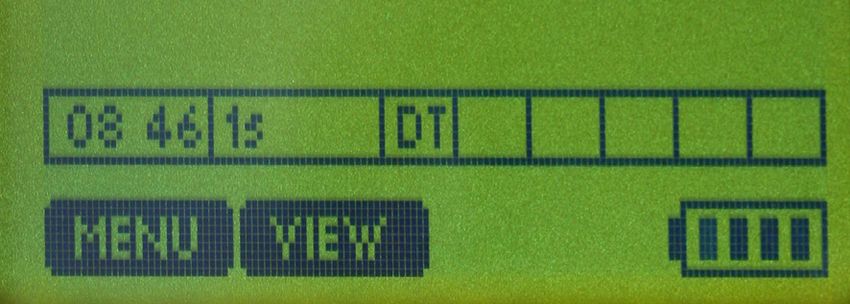
Fibox 3 LCD trace v7

              Specification:

              Fiber optic oxygen transmitter for use with non-
              invasive oxygen sensors & sensor probes

              Software version:

              LCDTRACEv204 (Oct 2009)

              Document filename: IM_Fibox_3_LCD_trace_v7_dv3

              All rights reserved. No parts of this work may be reproduced in any form or by any means -
              graphic, electronic, or mechanical, including photocopying, recording, taping, or information
              storage and retrieval systems - without the written permission of the publisher.

              Products that are referred to in this document may be either trademarks and/or registered
              trademarks of the respective owners. The publisher and the author make no claim to these
              trademarks.

              While every precaution has been taken in the preparation of this document, the publisher and
              the author assume no responsibility for errors or omissions, or for damages resulting from the
              use of information contained in this document or from the use of programs and source code
              that may accompany it. In no event shall the publisher and the author be liable for any loss of
              profit or any other commercial damage caused or alleged to have been caused directly or
              indirectly by this document.

              Specifications may change without prior notice.

              Manufacturer
              PreSens                  Josef-Engert-Str. 11        Phone +49 941 94272100    info@PreSens.de
              Precision Sensing GmbH   93053 Regensburg, Germany   Fax   +49 941 94272111    www.PreSens.de

© 2014 PreSens Precision Sensing GmbH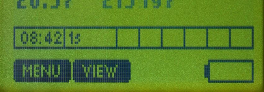

Table of Contents
                1       Preface ........................................................................................................................ 3

                2       Description of the Fibox 3 LCD trace Transmitter................................................... 4
                2.1     Scope of Delivery ....................................................................................................... 5
                2.2     Front Panel ................................................................................................................. 6
                2.3     Rear Panel .................................................................................................................. 7
                2.4     LCD Control Panel ..................................................................................................... 8

                3       Installation .................................................................................................................. 9
                3.1     Set-up .......................................................................................................................... 9
                3.2     Software Installation ................................................................................................ 10
                3.3     Battery Usage and Charging ................................................................................... 10

                4       Operation as Stand-alone Transmitter ................................................................... 13
                4.1     Starting the Device .................................................................................................. 13
                4.2     Calibration ................................................................................................................ 14
                4.2.1   Sensor Type Selection ............................................................................................ 15
                4.2.2   Calibration with Temperature ON ........................................................................... 15
                4.2.3   Calibration with Temperature OFF ......................................................................... 16
                4.2.4   Manual Calibration ................................................................................................... 17
                4.3     Measurement ............................................................................................................ 18
                4.4     Data Logging ............................................................................................................ 20
                4.5     Configuration ........................................................................................................... 22
                4.6     Diagnosis & Test ...................................................................................................... 24
                4.7     Menu Structure......................................................................................................... 25

                5       Operation - PC Controlled ....................................................................................... 26
                5.1     Adjustment of the Regional Settings of the Operating System ........................... 26
                5.2     USB Serial Driver Installation ................................................................................. 28
                5.3     Configuration of COM Port ..................................................................................... 30
                5.4     Starting the Device .................................................................................................. 32
                5.5     Calibration ................................................................................................................ 35
                5.5.1   Sensor Type Selection ............................................................................................ 35
                5.5.2   Calibration of PSt3 “with temperature sensor” ..................................................... 36
                5.5.3   Calibration of PSt3 “without temperature sensor” ............................................... 39
                5.5.4   Manual Calibration of PSt3 ..................................................................................... 41
                5.5.5   Calibration of PSt6 ................................................................................................... 42
                5.6     Measurement ............................................................................................................ 43
                5.6.1   Control Bar ............................................................................................................... 46
                5.6.2   Graphical Display..................................................................................................... 48
                5.7     Data Logger Reading ............................................................................................... 51
                5.8     Opening txt-Files in Excel ....................................................................................... 52
                5.9     Analog Output .......................................................................................................... 55
                5.10    Analog Input ............................................................................................................. 56
                5.11    LED Intensity ............................................................................................................ 57
                5.12    Software Menu Structure ........................................................................................ 58

© 2014 PreSens Precision Sensing GmbH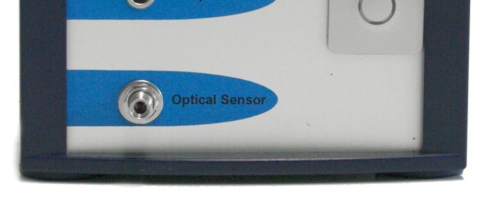
6      Technical Data .......................................................................................................... 59
                6.1    Specifications........................................................................................................... 59
                6.2    Analog Output and External Trigger ...................................................................... 61

                7      Operational Notes .................................................................................................... 64
                7.1    Optical Output .......................................................................................................... 64
                7.2    Temperature Compensation ................................................................................... 64
                7.3    Warm-Up Time.......................................................................................................... 64
                7.4    Power Adapter.......................................................................................................... 64
                7.5    Analog Outputs ........................................................................................................ 64
                7.6    RS232 Interface ........................................................................................................ 64
                7.7    Maintenance ............................................................................................................. 64
                7.8    Service ...................................................................................................................... 65

                8      CE and FCC Conformity .......................................................................................... 65

                9      Concluding Remarks ............................................................................................... 66

© 2014 PreSens Precision Sensing GmbH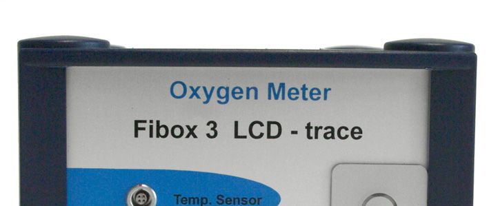
Fibox 3 LCD trace                                          3                                                       Preface

              1 Preface
                    You have chosen a new, innovative technology for measuring oxygen.

                    The Fibox 3 LCD trace is a compact easy to transport fiber optic oxygen transmitter for stand-
                    alone or PC controlled use. The data evaluation is PC supported. The Fibox 3 LCD trace was
                    developed especially for small fiber chemical optical oxygen sensors, flow-through cells and
                    integrated sensor systems. It is based on a novel technology, which creates very stable,
                    internally referenced measured values. This allows a more flexible use of oxygen sensors in
                    various fields of interest.

                    Optical oxygen sensors (also called optodes) have several important features:

                           They are small.
                           Their signal does not depend on the flow rate of the sample.
                           They can be physically divided from the measuring system which allows a non-
                           invasive measurement.
                           They can be used in disposables.

                    Therefore, they are ideally suited for the examination of small sample volumes, for highly
                    parallelized measurements in disposables, and for biotechnological applications.
                    A set of different oxygen minisensors, flow-through cells and integrated sensor systems is
                    available to make sure you have the sensor which matches your application.
                    Please feel free to contact our service team to find the best solution for your application.

                    Your PreSens Team

                    PLEASE READ THE FOLLOWING INSTRUCTIONS CAREFULLY BEFORE WORKING
                    WITH THIS DEVICE.

 © 2014 PreSens Precision Sensing GmbH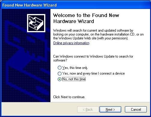
Fibox 3 LCD trace                                                    4                    Description of the Transmitter

              2 Description of the Fibox 3 LCD trace
                Transmitter
                    The Fibox 3 LCD trace is a single channel, temperature compensated, stand-alone oxygen
                    transmitter. It is used with fiber optic oxygen sensors based on 2 mm polymer fibers. The
                    device is portable with a rechargeable battery and a built-in data-logger. It can be controlled
                    via an integrated, programmable LCD control panel. Alternatively, the Fibox 3 LCD trace can
                    be connected to a PC for measurement. The Fibox 3 LCD trace is used for sensor coatings
                    type PSt3 (detection limit 15 ppb, 0 - 100 % oxygen), and type PSt6 (detection limit 1 ppb, 0 -
                    4.2 % oxygen).

                    Fig. 1 Fibox 3 LCD trace v7, fiber optic oxygen transmitter for
                           use with non-invasive oxygen sensors & sensor probes

                    Fibox 3 LCD trace v7 features:

                             Fiber optic oxygen transmitter with temperature compensation
                             High precision
                             Portable
                             Four analog outputs (two for current output 4 – 20 mA, two for
                             voltage output 0 - 10 V)
                             Two trigger inputs
                             Digital data output (on request)
                             External temperature measurement
                             Programmable sampling rate
                             128 x 64 pixel graphical LCD
                             Li-Ion Battery with 14.4 V / 3.9 Ah
                             RS232 interface
                             Internal data logger for up to 25,000 samples

 © 2014 PreSens Precision Sensing GmbH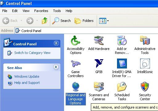
Fibox 3 LCD trace                                              5                          Description of the Transmitter

                    2.1 Scope of Delivery

                    Fig. 2 Case with all delivered equipment

                            Fiber optic oxygen transmitter Fibox 3 LCD trace v7
                            Software LCDTRACEv204
                            RS232 cable
                            Battery charger (Input 110 - 240 VAC, 50 – 60 Hz; Output: 16.8 VDC; max 2 A)
                            with EU- and US-power supply cord
                            Temperature sensor PT 1000
                            Printout of instruction manual

                    Additionally required equipment (not supplied):

                            Oxygen-sensitive chemical optical sensor
                            You can find mini sensors – mounted into different types of housings – on
                            www.presens.de/products
                            PC / Notebook for comfortable data recording, configuration and retrieval of data from
                            the data logger.
                            System requirements:
                            Win XP: Processor: 300 MHz or higher, RAM 256 MB (512 MB recommended)
                            Win Vista (32 bit): Processor: 1.86 GHz or higher, RAM 512 MB (1 GB
                            recommended)
                            Win 7 (32 / 64 bit): Processor: 1.86 GHz or higher, RAM 1GB or higher

 © 2014 PreSens Precision Sensing GmbH
Fibox 3 LCD trace 6 Description of the Transmitter
2.2 Front Panel
ON / OFF
Fig. 3 Transmitter front panel
The front panel is equipped with a connector for the fiber optic sensor, a connector for the
temperature sensor and an ON / OFF switch.
ELEMENT DESCRIPTION FUNCTION
ON / OFF ON / OFF switch Switches the device ON and OFF.
In case the charger is connected the indicator ring is
illuminated blue.
Optical SMA fiber connector Connect the fiber optic oxygen sensor here.
Sensor
Temp. Connector for PT 1000 Connect the PT 1000 temperature sensor for
Sensor temperature sensor temperature compensated measurements here.
© 2014 PreSens Precision Sensing GmbHFibox 3 LCD trace 7 Description of the Transmitter
2.3 Rear Panel
Fig. 4 Transmitter rear panel
The electrical specifications of all rear panel connectors are given in chapter 6 “Technical
Data”. Please follow these notes to avoid mistakes.
ELEMENT DESCRIPTION FUNCTION
POWER Line adapter for Connect the charger for the Li-Ion battery here.
battery charger
RS232 RS232 interface Connect the device with a RS232 data cable to
(male) your PC / notebook here.
Use the provided parts only.
V1 Analog voltage output/ Connector for analog input and output (Voltage 0 –
10 V). For further information see chapter 6
Analog voltage input
“Technical Data”.
(channel 1)
V2 Analog voltage output/ Connector for analog input and output (Voltage 0 –
10 V). For further information see chapter 6
Analog voltage input
“Technical Data”.
(channel 2)
I1 Analog current output Connector for analog output, current 4 – 20 mA.
(channel 1) For further information see chapter 6 “Technical
Data”.
I2 Analog current output Connector for analog output, current 4 – 20 mA.
(channel 2) For further information see chapter 6 “Technical
Data”.
© 2014 PreSens Precision Sensing GmbHFibox 3 LCD trace 8 Description of the Transmitter
2.4 LCD Control Panel
Fig. 5 LCD control panel for stand-alone
operation of the transmitter
The LCD display and the buttons allow operating the transmitter without connection to a PC.
In the lower part of the display the functions of the buttons in the respective menu, submenu
or window are shown. Use the buttons for navigating through the menu and to make settings;
pressing the respective button will perform the respective function (see Fig. 5).
© 2014 PreSens Precision Sensing GmbHFibox 3 LCD trace 9 Installation
3 Installation
3.1 Set-up
Fig. 6 Set-up for PC controlled use of the Fibox 3 LCD trace v7
A typical set-up for PC controlled use is shown in Fig. 6. A sensor spot is connected optically
via a polymer optical fiber i.e. to the transmitter, which is connected via a serial COM port to a
PC.
Remove the rubber cap from the optical sensor connector and keep the cap (Fig. 7). After
measurements or for storing the transmitter the rubber cap should be put back on to keep the
optical sensor connector clean.
! It is recommended to clean the SMA connector with a dry, dust free cleaning wipe or
cleaning implement for SMA connectors before the measurement.
Fig. 7 Remove the rubber cap from the oxygen
sensor connector.
© 2014 PreSens Precision Sensing GmbHFibox 3 LCD trace 10 Installation
Remove the protective cap from the male plug on the polymer optical fiber and insert it in the
SMA connector of the Fibox 3 LCD trace. The safety nut has to be screwed on.
There is a red mark on the temperature sensor connector of the Fibox 3 LCD trace. The
temperature sensor plug also has a red mark. Match those two marks before inserting the
temperature sensor plug into the connector on the transmitter front panel; else the plug might
get damaged.
3.2 Software Installation
The software is working with English and German regional settings. Please change your
setting to one of these settings before installing the software (see chapter 5.1).
1. Please close all other applications as they may interfere with the software.
2. Insert the supplied CD-ROM into the respective drive.
3. If no dialog opens automatically, use the explorer to open the file menu on the CD. Copy
the file „LCDTRACEv204.exe“ to a folder on your PC (e.g. C:\PreSens\…) and create a
shortcut to your desktop so you are able to start the software quickly.
4. Start the software by double clicking the symbol for the „LCDTRACEv204.exe” file.
3.3 Battery Usage and Charging
The Fibox 3 LCD comprises a rechargeable battery (accumulator, 14.4 V, 3.9 Ah) for
self-contained power supply. Rechargeable batteries may be replaced by the
manufacturer only. Rechargeable batteries are subject to normal wear which is more or
less pronounced depending on operating and storage conditions. This normal wear is
no defect which is covered by the device warranty.
! Prior to first use, the internal battery has to be charged.
! Only use the supplied battery charger (type mascot-9940) for the Li-ion battery.
! Disconnect the battery charger, when the battery is fully charged. Keeping the battery
charger permanently connected will increase the aging process of the battery.
! The battery is incorporated in the housing of the transmitter. Therefore, it cannot be
replaced by the customer. Alignment, rework or repair work may only be carried out by
the manufacturer.
! The charging time of the battery is approx. 3 – 4 hours. It is possible to take
measurements with connected charger.
! The maximum runtime of the rechargeable battery depends on the settings of the
device, the temperature and battery conditions (charging cycles, aging).
© 2014 PreSens Precision Sensing GmbHFibox 3 LCD trace 11 Installation
! The charger has an internal fuse which blows if a fault occurs in the charger. Such
faults must be repaired by qualified service personnel only.
! The Li-ion charger mascot-9940 is designed for indoor use only and should not come
into contact with water or dust. To prevent overheating the product should not be
covered whilst in use.
! The main sockets should be easily accessible. In the event of operational error, the
plug should be immediately removed from the socket.
! This charger is designed for use with Li-ion batteries. For safety reasons, this charger
must be used only for batteries which have the right number of cells in series: Output
voltage divided by 4.1 V or 4.2 V.
! The charger contains dangerous voltages and the cover should not be removed. All
service or maintenance work should be carried out by qualified personnel who can get
assistance by contacting the manufacturer´s agent.
! The charger is double-insulated (in insulation class II).
! If the battery charger is mounted in a vehicle it can only be used when the vehicle is
not in use.
! The charger has plastic casing therefore avoid it coming into contact with oils, grease
etc., as most types of plastic can be broken down by chemicals and solvents.
1. Do not connect the charger to the main power grid before it is connected to the
transmitter.
2. Connect the provided battery charger (type mascot-9940) to the transmitter (Fig. 8).
Fig. 8 Transmitter with connected battery
charger
© 2014 PreSens Precision Sensing GmbHFibox 3 LCD trace 12 Installation
3. Connect the charger to the main power grid.
4. The ON / OFF switch on the front panel is illuminated blue, indicating the charging
process (Fig. 9).
Fig. 9 The ON / OFF switch is illuminated blue,
indicating the charging process.
5. Let the battery charge for four hours.
The charging time of the battery is approximately three to four hours. It is possible to take
measurements with connected charger.
6. The LED on the charger indicates the following charge status:
Orange
Fast charge. The charger is in constant current mode.
Yellow
Final charge. The battery is normally 80 - 95 % charged when the LED-indicator
changes to yellow.
Green
Charge completed (the charge is stopped).
7. When the charging process is completed, disconnect the charger from the main power
grid before unplugging the battery connection.
© 2014 PreSens Precision Sensing GmbHFibox 3 LCD trace 13 Operation as Stand-alone Transmitter
4 Operation as Stand-alone Transmitter
4.1 Starting the Device
Press the ON / OFF switch on the front panel to start the transmitter.
Fig. 10 Transmitter front panel, ON / OFF switch
The device starts measuring with the settings of the last measurements.
By pressing VIEW you can choose between two different display views:
View 1:
The initial display view shows the current oxygen measurement value and oxygen unit
(e.g. [% air sat.] in Fig. 11). The current temperature value is displayed in the upper
right corner. In addition, the status bar shows the current time and sampling rate in the
status bar.
Fig. 11 LCD display – View 1
© 2014 PreSens Precision Sensing GmbHFibox 3 LCD trace 14 Operation as Stand-alone Transmitter
View 2:
The second display mode additionally shows raw data amplitude (Signal) and phase
(Phase) of the sensor and an error status (Error).
Fig. 12 LCD display – View 2
By pressing the MENU key you can activate different functions and readouts.
To make a selection use BACK, , , and ENTER. You can leave a submenu by pressing
BACK.
To make a measurement the following steps have to be completed:
1. Selecting the oxygen sensor type
2. Calibrating the oxygen sensor
3. Setting measurement parameters
4.2 Calibration
In the submenu MENU / Calibration / Status the currently used calibration data is shown:
Date of Calibration, Pressure, Phase1, Phase2, Temperature1 and Temperature2. Press
any key to leave this menu.
There are three different calibration modes:
MENU / Calibration / Calibrate / Temperature ON
In “Temperature ON” mode the current raw phase values of the oxygen sensor are
measured and stored. Temperature during calibration is measured and saved with the
current temperature measurement settings (PT 1000, External). The temperature
sensor has to be placed in close vicinity to the oxygen sensor or make sure that the
temperature at both oxygen and temperature sensor is the same.
MENU / Calibration / Calibrate / Temperature OFF
In “Temperature OFF” mode the current raw phase values of the oxygen sensor are
measured and stored. The temperature value during calibration is set manually on the
© 2014 PreSens Precision Sensing GmbHFibox 3 LCD trace 15 Operation as Stand-alone Transmitter
display and stored. This option can be used, if the temperature at the location of the
oxygen sensor is known.
MENU / Calibration / Calibrate / Manual
In “Manual” mode the raw phase values of the oxygen sensor as well as the
temperature values are set manually on the display. This option can be used if
previously measured calibration values for the currently used oxygen sensor are
available. You can find calibration data on the Final Inspection Protocol delivered with
you oxygen sensor (see also Fig. 41).
4.2.1 Sensor Type Selection
Prior to making measurements, you have to choose the correct sensor type. To change the
sensor type select MENU / Calibration / Sensortype. Press EDIT, choose the respective
sensor type you have connected to the transmitter, and then press ENTER.
The following sensor types can be used with the Fibox 3 LCD trace:
PSt3
PSt6
Please read the instruction manual of the respective oxygen sensor for more detailed
information about calibration standards and sensor specifications.
4.2.2 Calibration with Temperature ON
Select MENU / Calibration / Calibrate / Temperature ON. The calibration can be cancelled
by pressing EXIT. This will not change already made settings.
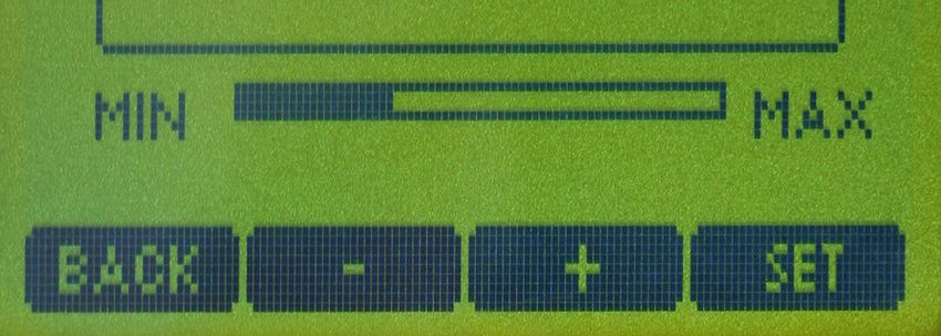
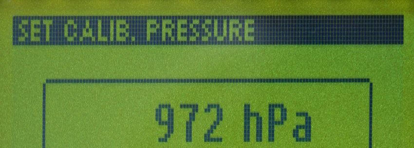
1. SET CALIB. PRESSURE
Set the current atmospheric pressure value by using the “+” and “–“ keys and press SET.
Fig. 13 LCD display – set calibration pressure
© 2014 PreSens Precision Sensing GmbHFibox 3 LCD trace 16 Operation as Stand-alone Transmitter
2. In case you are using a PSt6 oxygen sensor the OXYGEN of the 2nd CAL POINT is
requested in the unit “% air sat.” (= % O2 x 100 / 20.95). Change the oxygen value by
using the “+” and “-“ keys and press SET.
3. CAL0
For more detailed information on how to prepare the calibration standard 0 please see the
respective oxygen sensor´s instruction manual.
The message “Please insert the sensor into CAL0 solution“ is displayed. Place the oxygen
sensor in the medium for the first calibration point and press OK. The current phase and
temperature values are shown. Watch the displayed phase value; wait for about 3 minutes
until the phase angle is constant (the variation of the phase angle should be smaller than
± 0.1° and variation of temperature ± 0.1°C) then press STORE. (If the phase angle
exceeds the permitted range, the phase value display starts flashing and pressing the
STORE key will result in the error message “Overrange!”.)
4. CAL2nd
For more detailed information on how to prepare the calibration standard 100 please see
the respective oxygen sensor´s instruction manual.
The message “Please insert the sensor into CAL2nd solution“ is displayed. Place the
oxygen sensor in the medium for the second calibration point and press OK. The current
phase and temperature values are shown. Watch the displayed phase value; wait for
about 3 minutes until the phase angle is constant (the variation of the phase angle should
be smaller than ± 0.1° and variation of temperature ± 0.1°C) then press STORE. (If the
phase angle exceeds the permitted range, the phase value display starts flashing and
pressing the STORE key will result in the error message “Overrange!”.)
While storing the calibration data the display shows the message WAIT, then DONE and
afterwards switches back to the primary menu.
4.2.3 Calibration with Temperature OFF
Select MENU / Calibration / Calibrate / Temperature OFF. The calibration can be cancelled
by pressing EXIT. This will not change already made settings.
1. SET CALIB. TEMPERATURE
First, the temperature value at the oxygen sensor during calibration is requested. To use
this option you have to know the temperature at the location of the oxygen sensor. Set the
temperature for first and second calibration value manually by using the “+” and “-“ keys
and press SET.
2. SET CALIB. PRESSURE
Set the current atmospheric pressure value by using the “+” and “–“ keys and press SET.
In case you are using a PSt6 oxygen sensor the OXYGEN of the 2nd CAL POINT is
requested in the unit “% air sat.” (= % O2 x 100 / 20.95). Change the oxygen value by
using the “+” and “-“ keys and press SET.
3. CAL0
For more detailed information on how to prepare the calibration standard 0 please see the
respective oxygen sensor´s instruction manual.
The message “Please insert the sensor into CAL0 solution“ is displayed. Place the oxygen
sensor in the medium for the first calibration point and press OK. The current phase and
temperature values are shown. Watch the displayed phase value; wait for about 3 minutes
until the phase angle is constant (the variation of the phase angle should be smaller than
© 2014 PreSens Precision Sensing GmbHFibox 3 LCD trace 17 Operation as Stand-alone Transmitter
± 0.1°) then press STORE. (If the phase angle exceeds the permitted range, the phase
value display starts flashing and pressing the STORE key will result in the error message
“Overrange!”.)
4. CAL2nd
For more detailed information on how to prepare the calibration standard 100 please see
the respective oxygen sensor´s instruction manual.
The message “Please insert the sensor into CAL2nd solution“ is displayed. Place the
oxygen sensor in the medium for the second calibration point (= 100% air sat.) and press
OK. The current phase and temperature values are shown. Watch the displayed phase
value; wait for about 3 minutes until the phase angle is constant (the variation of the
phase angle should be smaller than ± 0.1°) then press STORE. (If the phase angle
exceeds the permitted range, the phase value display starts flashing and pressing the
STORE key will result in the error message “Overrange!”.)
While storing the calibration data the display shows the message WAIT, then DONE and
afterwards switches back to the primary menu.
4.2.4 Manual Calibration
Select MENU / Calibration / Calibrate / Manual. The calibration can be cancelled by
pressing EXIT. This will not change already made settings.
The following calibration values are requested one after another and have to be set manually:
1. CAL 0 PHASE
2. In case you are using a PSt6 oxygen sensor: OXYGEN of 2nd CAL POINT in “% air sat.”
3. CAL 2nd PHASE
4. CAL 0 TEMP (temperature)
5. CAL 2nd TEMP (temperature)
6. PRESSURE
Change each value by using the “+“ and “-“ keys and press SET.
While storing the calibration data the display shows the message WAIT, then DONE and
afterwards switches back to the primary menu.
© 2014 PreSens Precision Sensing GmbHFibox 3 LCD trace 18 Operation as Stand-alone Transmitter
4.3 Measurement
After sensor type selection and calibration the measurement parameters can be set.
Select MENU / Measurement; you can set the following parameters:
Sampling rate
Select the measurement point frequency. Sampling rates from fastest to 60 min can be set.
For the PSt3 sensor the fastest sampling rate is 1 second, for PSt6 it is 3 seconds. In
addition, any other sampling rate between 1 and 3,600 seconds can be chosen by selecting
other. Change the settings with the und keys and press ENTER.
Temperature
Select the temperature measurement mode for temperature compensated oxygen
measurement:
PT1000
With this setting the temperature value necessary for the temperature compensation
of the oxygen sensor is measured with the supplied PT 1000 temperature sensor.
Manual
With this setting a constant temperature value is set manually for temperature
compensated oxygen measurement. This option can be used, if the temperature at the
location of the oxygen sensor is known and stays constant during measurement.
Change the temperature value by using the “+“ and “-“ keys and press SET.
External
With this setting an external analog signal is transferred to the transmitter via one of
the analog connectors on the transmitter rear panel.
To use this option the settings in the submenu Configuration / Analog In / Channel 1
or Channel 2 have to be adjusted first. Please read more detailed information on
analog input in chapter 4.5 „Configuration“.
When the pre-settings in the submenu Analog In are completed the respective
channel can be selected in External. Now the analog input signal is captured, digitally
converted and used for correct temperature compensated measurement and oxygen
value calculation.
Sensor protec.
Select a maximum temperature for deactivating the measurement function. Setting a
temperature limit is supposed to protect the sensor. With increasing temperatures (e. g. in
autoclave or CIP cleaning processes) the optical excitation can cause accelerated sensor
aging. The sensor illumination will be turned off when the measured temperature (PT 1000,
Manual, External) reaches the selected maximum value. The message “Warning! Sensor
protection” is displayed.
The selection range is 20°C to 100°C. Change the temperature value by using the “+“ and “-“
keys and press SET. The default value is set to 40 °C.
© 2014 PreSens Precision Sensing GmbHFibox 3 LCD trace 19 Operation as Stand-alone Transmitter
Signal average
This function is for more experienced users. You can select automatic or manual internal
averaging of data points per measurement point. Depending on the signal amplitude of the
sensor the illumination time per measurement point can be adjusted. With a higher
illumination level the signal-to-noise ratio can be improved, with a lower illumination level
sensor bleaching can be avoided and its measurement stability prolonged.
There are two options. With AUTO the pulse length in illumination gets adjusted automatically
by the device, with Manual the pulse length can be selected in a range from 1 to 4. With
higher selected value the illumination time increases and more single measurement points
are used for averaging one measurement point. Change the setting by using the “+“ and “-“
keys and press SET.
Oxygen unit
Select the desired oxygen unit. Change the setting with the and keys and press ENTER.
These options are available:
% air sat.
% oxy. sat.
hPa
Torr
ppm (ppb)
µmol/l
Sig. intensity
This function is for more experienced users to change the illumination level of the device.
With a higher illumination level the signal-to-noise ratio can be improved, with a lower
illumination level sensor bleaching can be avoided and its measurement stability prolonged.
! A change in signal intensity will invalidate the calibration values of the sensor and it
has to be recalibrated. The display also shows the warning message “This can
change calibration values“.
The selection range is 5 % to 100 %. Change the setting by using the “+“ and “-“ keys and
press SET.
Submenus can be selected using the and keys and pressing EDIT switches to editing
mode. When all required settings are done, go back to the main view on the display by
pressing BACK. Measurements are now based on the performed calibration and the new
measurement settings.
© 2014 PreSens Precision Sensing GmbHFibox 3 LCD trace 20 Operation as Stand-alone Transmitter
4.4 Data Logging
The transmitter has an internal data logger for up to 25,000 samples. The maximum saving
time depends on the sampling rate selected.
! The data logging mode is only accessible if the transmitter is used as stand-alone
device. The transmitter cannot be used with the PC software while in data logging
mode.
! At delivery the data logging mode of your transmitter is not activated by default
setting.
! While data is being stored submenus cannot be accessed. The only options are to
cancel the data logging mode or to switch to the data logging status display. Select
Menu / Data logging / EDIT / Status to get the following information: Start time,
start date, sampling rate, data in memory, free memory and MAX memory size.
While the Status is displayed no data is being stored.
! The device can be turned off while in data logging mode. Data sampling and logging is
continued as soon as the device is turned back on and has initialized.
! Pressing Start will overwrite stored measurement data. To save previously stored
data connect the device to a PC / notebook and retrieve the data via the software.
After calibration and setting measurement parameters, the data logging mode can be
activated by selecting Menu / Data logging / EDIT / Start. The warning message “This will
erase previously stored data!” is displayed. Press OK to confirm and the maximum possible
sampling time is shown. Again confirm with OK. The display shows DONE and then switches
back to the main measurement view automatically. The symbol DT in the status bar indicates
the activated data logging mode.
Fig. 14 LCD display showing activated data logging mode
© 2014 PreSens Precision Sensing GmbHFibox 3 LCD trace 21 Operation as Stand-alone Transmitter
To cancel the data logging mode select MENU / STOP and confirm with OK. After that
connect the transmitter to a PC / notebook and start the software. (Please see chapter 5.4 for
more detailed information about using the software for data retrieval.)
An example for a measurement file recorded with the data logger is shown in Fig. 15.
***** DESCRIPTION ***********;
Test file for evaluation purpose;
***** SOFTWARE INFO *********;
OxyView – LCDTRACE-V2.04 10/2009;
by PreSens GmbH;
22/07/10;
22:59:27;
***** Calibration Information *******;
DTL Start Date :18/06/10
DTL Start Time :21:14:48
Phase Cal 0 :66.01
Phase Cal 100 :31.84
Temp Cal 0 :20
Temp Cal 100 :20
Pressure :964
Sensor Type :2
cal 2 Air Sat% :100
Oxygen Unit :% air sat.
------------------------------------------
Date/Time(m/s); Oxygen[% air sat.]; Phase; Amplitude; Temperature[°C]; Error;
18.06.2010 21:14:48; 145.924; 27.27; 221750; 21.70; E0;
18.06.2010 21:14:49; 144.152; 27.42; 222375; 21.60; E0;
18.06.2010 21:14:50; 144.284; 27.41; 222375; 21.60; E0;
18.06.2010 21:14:51; 144.416; 27.40; 222500; 21.60; E0;
18.06.2010 21:14:52; 144.284; 27.41; 222500; 21.60; E0;
18.06.2010 21:14:53; 144.020; 27.43; 222500; 21.60; E0;
18.06.2010 21:14:54; 144.152; 27.42; 222500; 21.60; E0;
Fig. 15 Example for a measurement file recorded with data logger
© 2014 PreSens Precision Sensing GmbHFibox 3 LCD trace 22 Operation as Stand-alone Transmitter
4.5 Configuration
Select MENU / Configuration. Submenus can be selected using the and keys and
pressing EDIT switches to editing mode.
The following configurations can be adjusted:
Status
Status displays the current device parameters like illumination level (Sig.intensity), internal
referencing (Ref. current, Ref. amplitude), internal measurement averaging (Sig. average)
and the temperature compensation mode (Temp. comp.). Press any key to leave this menu.
Analog out
In the Analog out menu parameters for the analog output can be selected.
There are four analog out channels available (two voltage and two current channels, Voltage
U1, Voltage U2, Current I1, Current I2).
The following parameters can be selected for each channel:
Inactive (no analog output)
Oxygen
Temperature
Phase
Amplitude
The additional submenu 20mA/10V value allows setting a conversion rate for maximum
possible analog output. Depending on the selected oxygen unit the maximum oxygen value
corresponding to the maximum output of 20 mA or 10 V can be set.
For example, 10 V can be set to 100 % air-saturation, then 1 V corresponds to 10% air-
saturation; or 10 V can be set to 200 ppm gaseous oxygen, then 1 V corresponds to 20 ppm.
Analog in
The transmitter has two analog in channels which allow feeding an external analog signal to
the device. A temperature value measured by an external device can be transferred to the
transmitter as voltage in a range from 0 to 10 V.
In the submenus Channel U1/Variable and Channel U2/Variable you can choose between
the options Inactive and Temperature. The submenu /Range allows assigning a lowest
temperature value to the voltage of 0 V (Low value) and a highest temperature value to the
voltage of 10 V (High value). This equals a two point calibration for the external voltage. The
assignment of “Low value” and “High value” is only possible, if the variable Temperature is
selected.
For example: If the input signal of 10 V corresponds to temperature of 60°C, you should set
the value in the High value control window to 60; and if the input signal of 0 V corresponds to
temperature of 10°C, you should set the value in the Low value control window to 10.
With an input voltage of 5 V the imported temperature will be 35 °C in this case, or with an
input voltage of 7.5 V it will be 47.5 °C.
© 2014 PreSens Precision Sensing GmbHFibox 3 LCD trace 23 Operation as Stand-alone Transmitter
! Before starting external temperature compensation it is useful to check the quality of
electric signals. This can be done by entering the submenu Diag&Test / Analog In.
The input voltage can be controlled directly on the LCD panel.
Clock/Date
This menu allows changing the current date and time settings. Change between positions by
pressing Next and adjust the setting using the “+” key. Save the changes with SET or cancel
the process by pressing Back.
Display
There are three different settings for background illumination:
OFF background illumination is turned off
ON background illumination is permanently turned on
AUTO background illumination is activated by pressing any key and turns back off
after 10 sec., if no other key is pressed.
Change the setting with the and keys and press ENTER or cancel the process by
pressing BACK.
Reset config
The menu Reset config allows resetting all parameters to default settings. Solely use this
function if you are experienced in it or contact our service team.
MENU SUBMENU DEFAULT SETTING
Measurement Sampling rate Fastest
Temperature PT 1000
Signal average Auto
Oxygen unit % air sat.
Sig. intensity 25 %
Calibration Sensor type PSt3
Data logging Off
Configuration Analog out All inactivated
Analog in All inactivated
Clock / Date Reset to 010104 00:00:00
Display ON
© 2014 PreSens Precision Sensing GmbHFibox 3 LCD trace 24 Operation as Stand-alone Transmitter
4.6 Diagnosis & Test
The menu Diag&Test is for more experienced users to test particular transmitter functions.
System
System shows the current hardware version and serial number. Press any key to leave this
menu.
Output
This function allows simulating output values for each of the four output channels. Change to
the respective channel first (Voltage 1, Voltage 2, Current 1, Current 2). Then select the
value that should be issued at the output channel by using the “+” and “-“ keys. The currently
selected and displayed value is issued directly. Check the output with an external
measurement device or a data logger. Press any key to leave this menu.
Input
An input voltage fed from an external device can be tested like the analog output described
above. Select the respective channel (Channel 1 or Channel 2). The voltage at the analog
output is measured and its value is displayed. Press any key to leave this menu.
© 2014 PreSens Precision Sensing GmbHFibox 3 LCD trace 25 Operation as Stand-alone Transmitter
4.7 Menu Structure
MAIN SUBMENU 1 SUBMENU 2 SUBMENU 3
Measurement Sampling rate fastest
5 sec
10 sec
30 sec
1 min
other 1 … 3600 sec
Temperature PT 1000
Manual -10 …60 °C
External Channel U1, Channel
U2
Sensor protect. 20 … 100 °C
Signal average Auto
Manual 1…4
Oxygen unit % air sat.
% oxy. sat.
hPa
Torr
ppm (ppb)
µmol/l
Sig. intensity 5 … 100 %
Calibration Status
Calibration Temperature ON
Temperature OFF
Manual
Sensor type PST3
PST6
Data logging OFF Status
Stop
Configuration Status
Analog out Voltage U1
20 mA / 10 V value
Analog in Channel 1
Clock / Date
Display
Reset confi.
Diag & Test System
Outputs Voltage 1
Voltage 2
Current 1
Current 2
Inputs Channel 1
Channel 2
© 2014 PreSens Precision Sensing GmbHFibox 3 LCD trace 26 Operation - PC Controlled
5 Operation - PC Controlled
5.1 Adjustment of the Regional Settings of the Operating
System
The software is working with English and German regional settings.
To change the regional settings on your PC press Start and go to the Control Panel. Choose
Regional and Language Options.
Fig. 16 Control Panel – Classic View
Select the Regional Options tab (e.g. English (United States)) and click Customize.
Fig. 17 Regional and Laguage Options window
© 2014 PreSens Precision Sensing GmbHFibox 3 LCD trace 27 Operation - PC Controlled
A window opens; select the Numbers tab and choose the dot `.´ in the Decimal Symbol drop
down menu. In the drop down menu Digit grouping symbol you have to choose space ` ´.
Then press Apply and OK.
Fig. 18 Customize Regional Options window – Numbers tab
Click Customize again and go to the Date tab now. In the drop down menu Short date
format you have to select `dd.MM.yy´ and choose the dot `.´ in Date separator. Again press
Apply and OK.
Fig. 19 Customize Regional Options window – Date tab
© 2014 PreSens Precision Sensing GmbHFibox 3 LCD trace 28 Operation - PC Controlled
Press OK in the Regional and Language Options window, and you have finished adjusting
the regional settings.
5.2 USB Serial Driver Installation
! The USB-RS232-Binder423 and the respective driver are NOT included in the scope of
delivery.
The USB-RS232-Binder423 requires
At least one available USB port
Windows XP / Vista / Windows 7
Connect the USB serial cable to the PC / notebook and insert the delivered driver CD.
The Found New Hardware Wizard will launch automatically. Select No, not this time from
the options and click Next.
Fig. 20 Found New Hardware Wizard
© 2014 PreSens Precision Sensing GmbHFibox 3 LCD trace 29 Operation - PC Controlled
Select Install from a list or specific location (Advanced); then click Next.
Fig. 21 Found New Hardware Wizard
Select Search for the best driver in these locations and go to Search for removable
media (floppy, CD-ROM…). Click Next to proceed.
Fig. 22 Found New Hardware Wizard
Then Windows will copy the required driver files. Windows should then display a message
indicating that the installation was successful. Click Finish to complete the installation.
© 2014 PreSens Precision Sensing GmbHFibox 3 LCD trace 30 Operation - PC Controlled
5.3 Configuration of COM Port
To check which COM port is assigned to the USB serial cable press Start and go to the
Control Panel. Select System.
Select the Hardware tab in the System Properties window and click Device Manager.
Fig. 23 System Properties window
You can find the USB serial Port under Ports (COM & LPT) (in the figure below this would be
COM port 6 for example).
Fig. 24 Device Manager – USB Serial Port selected
© 2014 PreSens Precision Sensing GmbHFibox 3 LCD trace 31 Operation - PC Controlled
! Fibox 3 LCD trace only accepts COM port numbers that are < 10. In case the COM port
number is 10 or higher please change it to a port number < 10.
To change the COM port number you open the Device Manager activate Port (COM & LPT)
and double-click the USB-Serial Port. A window opens; select the Port Settings tab and click
on Advanced.
Fig. 25 USP Serial Port Properties – Port Settings tab
Change the COM Port Number to a free port number < 10 and click OK.
Fig. 26 Advanced Settings for COM Port window
Then you have to confirm the new port number by clicking OK; then you can close the device
manager.
© 2014 PreSens Precision Sensing GmbHFibox 3 LCD trace 32 Operation - PC Controlled
5.4 Starting the Device
1. Connect the Fibox 3 LCD trace via the supplied serial cable to a serial COM port of your
PC / notebook.
2. Connect the power supply.
3. Please close all other applications as they might interfere with the software. Start the
LCDTRACEv204 software.
Fig. 27 Initial window – software is scanning to detect the connected Fibox 3 LCD trace
The software is scanning all COM ports available to detect the connected Fibox 3 LCD trace.
The message “Search for device” is displayed.
© 2014 PreSens Precision Sensing GmbHFibox 3 LCD trace 33 Operation - PC Controlled
If the software is unable to detect the correct COM port, the dialog Select COM Port opens
(Fig. 28). Select the correct COM port and click the OK button.
Fig. 28 Dialog to select COM port
! If no device is detected, please check all connections and proper installation of serial
COM ports.
© 2014 PreSens Precision Sensing GmbHFibox 3 LCD trace 34 Operation - PC Controlled
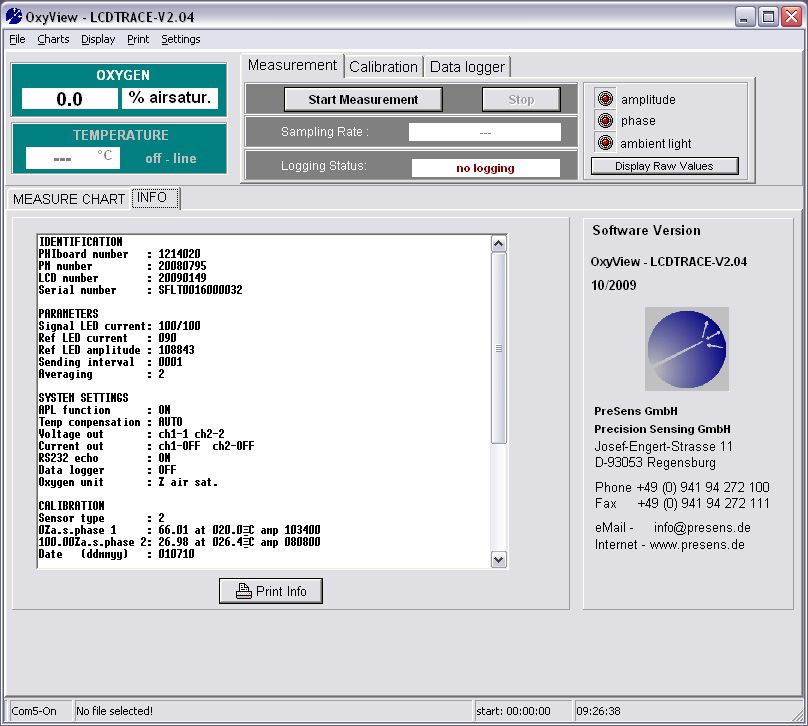
The window shown below is displayed after the connected transmitter got detected. The
transmitter can now be operated via the software.
Fig. 29 Initial display of the LCDTRACEv204 software
Now connect the oxygen sensor and temperature sensor to the respective connectors on the
transmitter front panel.
© 2014 PreSens Precision Sensing GmbHFibox 3 LCD trace 35 Operation - PC Controlled
5.5 Calibration
Click the Calibration tab in the upper middle screen.
Fig. 30 Calibration tab
There are three different calibration modes:
With the setting with temperature sensor the current raw phase values of the oxygen
sensor are measured and stored. Temperature during calibration is measured and
saved with the current temperature measurement settings (PT 1000, External). The
temperature sensor has to be in close vicinity to the oxygen sensor or make sure that
the temperature at both oxygen and temperature sensor is the same.
With the setting without temperature sensor the current raw phase values of the
oxygen sensor are measured and stored. The temperature value during calibration is
set manually in the software and stored. This option can be used, if the temperature
at the location of the oxygen sensor is known.
With the setting manually the raw phase values of the oxygen sensor as well as the
temperature values are set manually in the software. This option can be used, if
previously measured calibration values for the currently used oxygen sensor are
available. You can find calibration data on the Final Inspection Protocol delivered with
your oxygen sensor.
5.5.1 Sensor Type Selection
The correct sensor type has to be selected before starting the calibration process. In the
submenu Settings / Sensor the list of different sensor types is shown and the respective
sensor type can be selected:
PSt3
PSt6
© 2014 PreSens Precision Sensing GmbHFibox 3 LCD trace 36 Operation - PC Controlled
Fig. 31 Submenu for sensor type selection
Please read the instruction manual of the respective oxygen sensor for more detailed
information about its features.
5.5.2 Calibration of PSt3 “with temperature sensor”
Clicking on with temperature sensor opens the respective Calibration Menu dialog:
Fig. 32 Dialog for calibration with temperature sensor
© 2014 PreSens Precision Sensing GmbHFibox 3 LCD trace 37 Operation - PC Controlled
1. Insert the current atmospheric pressure value.
2. Set the first calibration point (0 % air sat.).
Place the oxygen sensor and temperature sensor in the medium for the first calibration
point. At the bottom of the dialog the currently measured amplitude and phase value of
the oxygen sensor and the temperature are displayed. Watch the displayed phase value;
wait for about 3 minutes until the phase angle is constant (the variation of the phase angle
should be smaller than ± 0.1° and variation of temperature ± 0.1°C) and click the Store
current value button to the right of the 1st point value. The transmitter stores amplitude,
phase and temperature values.
Fig. 33 Dialog for calibration with temperature sensor –
storing the first calibration value
A warning message is displayed saying this will overwrite the existing calibration values;
the 1st point values will be updated.
Fig. 34 Calibration Message window
3. Set the second calibration point (100 % air sat.).
Place the oxygen sensor and temperature sensor in the medium for the second calibration
point. At the bottom of the dialog the currently measured amplitude and phase value of
the oxygen sensor and the temperature are displayed. Watch the displayed phase value;
wait for about 3 minutes until the phase angle is constant (the variation of the phase angle
should be smaller than ± 0.1° and variation of temperature ± 0.1°C) and click the Store
current value button to the right of the 2nd point value. The transmitter stores amplitude,
phase and temperature values.
© 2014 PreSens Precision Sensing GmbHFibox 3 LCD trace 38 Operation - PC Controlled
Fig. 35 Dialog for calibration with temperature sensor –
storing second calibration value
A warning message is displayed saying this will overwrite the existing calibration
values; the 2nd point values will be updated.
End the calibration process by clicking the button Finish. The calibration data is stored to the
transmitter and the display in the INFO tab will be updated.
Stop the calibration by clicking the CANCEL button; cancelling the calibration is no longer
possible, if one of the Store current value buttons has already been pressed.
© 2014 PreSens Precision Sensing GmbHFibox 3 LCD trace 39 Operation - PC Controlled
5.5.3 Calibration of PSt3 “without temperature sensor”
Clicking on without temperature sensor opens the respective Calibration Menu dialog:
Fig. 36 Dialog for calibration without temperature sensor
1. Insert the current atmospheric pressure value.
2. Set the first calibration point (0 % air sat.).
Place the oxygen sensor in the medium for the first calibration point. At the bottom of the
dialog the currently measured amplitude and phase value of the oxygen sensor are
displayed. Set the current temperature at the oxygen sensor by using the up and down
arrows or typing in the temperature value. Watch the displayed phase value; wait for
about 3 minutes until the phase angle is constant (the variation of the phase angle should
be smaller than ± 0.1°) and click the Store current value button to the right of the 1st
point value. The transmitter stores amplitude, phase and temperature values.
© 2014 PreSens Precision Sensing GmbHFibox 3 LCD trace 40 Operation - PC Controlled
Fig. 37 Dialog for calibration without temperature sensor -
storing the first calibration value
A warning message is displayed saying this will overwrite the existing calibration
values; the 1st point values will be updated.
Fig. 38 Calibration Message window
3. Set the second calibration point (100 % air sat.).
Place the oxygen sensor in the medium for the second calibration point. At the bottom of
the dialog the currently measured amplitude and phase value of the oxygen sensor are
displayed. Set the current temperature at the oxygen sensor by using the up and down
arrows or typing in the temperature value. Watch the displayed phase value; wait for
about 3 minutes until the phase angle is constant (the variation of the phase angle should
be smaller than ± 0.1°) and click the Store current value button to the right of the 2nd
point value. The transmitter stores amplitude, phase and temperature values.
Fig. 39 Dialog for calibration without temperature sensor –
storing the second calibration value
A warning message is displayed saying this will overwrite the existing calibration
values; the 2nd point values will be updated.
© 2014 PreSens Precision Sensing GmbHFibox 3 LCD trace 41 Operation - PC Controlled
End the calibration process by clicking the button Finish. The calibration data is stored to the
transmitter and the display in the INFO tab will be updated.
Stop the calibration by clicking the CANCEL button; cancelling the calibration is no longer
possible, if one of the Store current value buttons has already been pressed.
5.5.4 Manual Calibration* of PSt3
Clicking on manually opens the Calibration Menu dialog for user defined calibration:
Fig. 40 Dialog for user defined calibration
You can find calibration data on the Final Inspection Protocol (FIP) delivered with your oxygen
sensor (see Fig. 41). Use the values in the grey highlighted boxes to fill in the Calibration
Menu. If previously measured calibration values for the used oxygen sensor are available you
can also use these values for the manual calibration.
1. Insert the atmospheric pressure at which the calibration data you are using were
measured. (In case you are using the FIP data use the pressure value in the grey
highlighted box.)
2. Select phase and temperature value for the first calibration point.
3. Select phase and temperature value for the second calibration point.
*Technical data relate to sensor specific calibration.
© 2014 PreSens Precision Sensing GmbHFibox 3 LCD trace 42 Operation - PC Controlled
Data
Atmospheric
pressure: 972 hPa
Phase Valid Valid
Temperature Amplitude
signal range range
[°] [°] [C°] [C°] [µV]
cal 0
60.41 58 - 62 20 18.0 - 22.0 94788
0% air sat
cal 2nd
26.77 25 - 29 20 18.0 - 22.0 38687.5
100 % air sat
Response time
[t90]: < 60 s Valid range: < 60 s
Please type in these values into the software for "manual
calibration"
Fig. 41 Example for a Final Inspection Protocol
End the calibration process by clicking the button Finish. A warning message is displayed
saying this will overwrite the existing calibration values. The calibration data is stored to the
transmitter and the display in the INFO tab will be updated. Abort the calibration by clicking
the CANCEL button.
5.5.5 Calibration of PSt6
The PSt6 sensor calibration is done the same way as described in paragraphs 5.5.2 - 5.5.4
with the only exception that the oxygen value at the second calibration point is requested in %
air sat. in all three calibration modes (with temperature / without temperature / manually).
Fig. 42 PSt6 calibration – select the oxygen value in “% air
sat.” for the second calibration point
© 2014 PreSens Precision Sensing GmbHYou can also read