Absolute Singleturn Encoders - CANOPEN - Your Global Automation Partner - pdb.turck.de
←
→
Page content transcription
If your browser does not render page correctly, please read the page content below
Your Global Automation Partner

Absolute Singleturn Encoders
CANOPEN
Type RS-52 (shaft)/
RS-53 (Blind hollow shaft)
Manual
Turck Inc. sells its products through Authorized Distributors. These distributors provide our
                 customers with technical support, service and local stock. Turck distributors are located
                               nationwide – including all major metropolitan marketing areas.
                    For Application Assistance or for the location of your nearest Turck distributor, call:
                                                       1-800-544-7769

            Specifications in this manual are subject to change with out notice. Turck also reserves the right to
            make modifications and makes no guarantee of the accuracy of the information contained herein.
                                       Literature and Media questions or concerns?
                                     Contact Marketing Turck USA – media@turck.com

2   Turck Inc. | 3000 Campus Drive, Minneapolis, MN 55441 | T +1 800 544 7769 | F +1 763 553 0708 | www.turck.com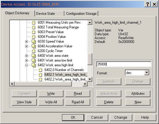
Contents
1 General .  .  .  .  .  .  .  .  .  .  .  .  .  .  .  .  .  .  .  .  .  .  .  .  .  .  .  .  .  .  .  .  .  .  .  .  .  .  .  .  .  .  .  .  .  .  .  .  .  .  .  .  .  .  .  .  .  .  .  .  .  .  .  .  .  .  .  .  .  .  .  .  .  .  .  .  .  .  .  .  .  .  .  .  .  .  .  .  .  .  .  .  .  .  . 6
CANopen Singleturn Encoder Type RS-52/RS-53 . . . . . . . . . . . . . . . . . . . . . . . . . . . . . . . . . . . . . . . . . . . . . . . . . . . . . . . . . . . . . . . . 6
The CANopen Communication Profile DS 301 V4.02 . . . . . . . . . . . . . . . . . . . . . . . . . . . . . . . . . . . . . . . . . . . . . . . . . . . . . . . . . . . . 6
Encoder Device Profile DS 406 V3.1  . . . . . . . . . . . . . . . . . . . . . . . . . . . . . . . . . . . . . . . . . . . . . . . . . . . . . . . . . . . . . . . . . . . . . . . . . . . . 6
Objectives of LSS  . . . . . . . . . . . . . . . . . . . . . . . . . . . . . . . . . . . . . . . . . . . . . . . . . . . . . . . . . . . . . . . . . . . . . . . . . . . . . . . . . . . . . . . . . . . . . 7
Data Transmission  . . . . . . . . . . . . . . . . . . . . . . . . . . . . . . . . . . . . . . . . . . . . . . . . . . . . . . . . . . . . . . . . . . . . . . . . . . . . . . . . . . . . . . . . . . . . 7
Objects and Function Code in the Predefined Connection Set . . . . . . . . . . . . . . . . . . . . . . . . . . . . . . . . . . . . . . . . . . . . . . . . . . 7
Broadcast (Network-Wide) Objects  . . . . . . . . . . . . . . . . . . . . . . . . . . . . . . . . . . . . . . . . . . . . . . . . . . . . . . . . . . . . . . . . . . . . . . . . . . . . 7
Peer-To Peer (Device-To-Device) Objects . . . . . . . . . . . . . . . . . . . . . . . . . . . . . . . . . . . . . . . . . . . . . . . . . . . . . . . . . . . . . . . . . . . . . . . 8
Restricted, Reserved Objects  . . . . . . . . . . . . . . . . . . . . . . . . . . . . . . . . . . . . . . . . . . . . . . . . . . . . . . . . . . . . . . . . . . . . . . . . . . . . . . . . . . 8
2 Transmission of Process Data  .  .  .  .  .  .  .  .  .  .  .  .  .  .  .  .  .  .  .  .  .  .  .  .  .  .  .  .  .  .  .  .  .  .  .  .  .  .  .  .  .  .  .  .  .  .  .  .  .  .  .  .  .  .  .  .  .  .  .  .  .  .  .  .  .  .  .  .  .  .  .  .  .  . 9
Transmit PDO1 (1800H) Position Asynchronous . . . . . . . . . . . . . . . . . . . . . . . . . . . . . . . . . . . . . . . . . . . . . . . . . . . . . . . . . . . . . . . . 9
Transmit PDO2 (1801H) Position Synchronous (SYNC-MODE) . . . . . . . . . . . . . . . . . . . . . . . . . . . . . . . . . . . . . . . . . . . . . . . . . . . 9
Transmit PDO3 (1802H) Velocity Asynchronous  . . . . . . . . . . . . . . . . . . . . . . . . . . . . . . . . . . . . . . . . . . . . . . . . . . . . . . . . . . . . . . . . 9
3 Transmission of Service Data .  .  .  .  .  .  .  .  .  .  .  .  .  .  .  .  .  .  .  .  .  .  .  .  .  .  .  .  .  .  .  .  .  .  .  .  .  .  .  .  .  .  .  .  .  .  .  .  .  .  .  .  .  .  .  .  .  .  .  .  .  .  .  .  .  .  .  .  .  .  .  .  .  .  . 10
Example: Transmission of Service Data to and from the Encoder . . . . . . . . . . . . . . . . . . . . . . . . . . . . . . . . . . . . . . . . . . . . . . . . 11
LSS Hardware Restrictions (LSS Address) . . . . . . . . . . . . . . . . . . . . . . . . . . . . . . . . . . . . . . . . . . . . . . . . . . . . . . . . . . . . . . . . . . . . . . . 11
LSS Operating Restrictions  . . . . . . . . . . . . . . . . . . . . . . . . . . . . . . . . . . . . . . . . . . . . . . . . . . . . . . . . . . . . . . . . . . . . . . . . . . . . . . . . . . . . 11
LSS Configurations and the Operation Modes . . . . . . . . . . . . . . . . . . . . . . . . . . . . . . . . . . . . . . . . . . . . . . . . . . . . . . . . . . . . . . . . . . 11
4 Power Supply and CAN-BUS Connection .  .  .  .  .  .  .  .  .  .  .  .  .  .  .  .  .  .  .  .  .  .  .  .  .  .  .  .  .  .  .  .  .  .  .  .  .  .  .  .  .  .  .  .  .  .  .  .  .  .  .  .  .  .  .  .  .  .  .  .  .  .  .  . 12
Power Supply . . . . . . . . . . . . . . . . . . . . . . . . . . . . . . . . . . . . . . . . . . . . . . . . . . . . . . . . . . . . . . . . . . . . . . . . . . . . . . . . . . . . . . . . . . . . . . . . . 12
CAN - M12 Connector  . . . . . . . . . . . . . . . . . . . . . . . . . . . . . . . . . . . . . . . . . . . . . . . . . . . . . . . . . . . . . . . . . . . . . . . . . . . . . . . . . . . . . . . . 12
Mechanical Characteristics . . . . . . . . . . . . . . . . . . . . . . . . . . . . . . . . . . . . . . . . . . . . . . . . . . . . . . . . . . . . . . . . . . . . . . . . . . . . . . . . . . . . 12
5 Initial Startup - General Device Setting .  .  .  .  .  .  .  .  .  .  .  .  .  .  .  .  .  .  .  .  .  .  .  .  .  .  .  .  .  .  .  .  .  .  .  .  .  .  .  .  .  .  .  .  .  .  .  .  .  .  .  .  .  .  .  .  .  .  .  .  .  .  .  .  .  . 13
Baudrate . . . . . . . . . . . . . . . . . . . . . . . . . . . . . . . . . . . . . . . . . . . . . . . . . . . . . . . . . . . . . . . . . . . . . . . . . . . . . . . . . . . . . . . . . . . . . . . . . . . . . . 13
Node Number  . . . . . . . . . . . . . . . . . . . . . . . . . . . . . . . . . . . . . . . . . . . . . . . . . . . . . . . . . . . . . . . . . . . . . . . . . . . . . . . . . . . . . . . . . . . . . . . . 13
CAN-BUS Termination . . . . . . . . . . . . . . . . . . . . . . . . . . . . . . . . . . . . . . . . . . . . . . . . . . . . . . . . . . . . . . . . . . . . . . . . . . . . . . . . . . . . . . . . . 13
Save All Bus Parameter . . . . . . . . . . . . . . . . . . . . . . . . . . . . . . . . . . . . . . . . . . . . . . . . . . . . . . . . . . . . . . . . . . . . . . . . . . . . . . . . . . . . . . . . 13
6 Layer Setting Services (LSS) .  .  .  .  .  .  .  .  .  .  .  .  .  .  .  .  .  .  .  .  .  .  .  .  .  .  .  .  .  .  .  .  .  .  .  .  .  .  .  .  .  .  .  .  .  .  .  .  .  .  .  .  .  .  .  .  .  .  .  .  .  .  .  .  .  .  .  .  .  .  .  .  .  .  .  . 14
7 Default Settings on Delivery  .  .  .  .  .  .  .  .  .  .  .  .  .  .  .  .  .  .  .  .  .  .  .  .  .  .  .  .  .  .  .  .  .  .  .  .  .  .  .  .  .  .  .  .  .  .  .  .  .  .  .  .  .  .  .  .  .  .  .  .  .  .  .  .  .  .  .  .  .  .  .  .  .  .  . 16
Communication Parameter . . . . . . . . . . . . . . . . . . . . . . . . . . . . . . . . . . . . . . . . . . . . . . . . . . . . . . . . . . . . . . . . . . . . . . . . . . . . . . . . . . . . 16
Encoder Profile . . . . . . . . . . . . . . . . . . . . . . . . . . . . . . . . . . . . . . . . . . . . . . . . . . . . . . . . . . . . . . . . . . . . . . . . . . . . . . . . . . . . . . . . . . . . . . . . 17
8 Communication Parameter .  .  .  .  .  .  .  .  .  .  .  .  .  .  .  .  .  .  .  .  .  .  .  .  .  .  .  .  .  .  .  .  .  .  .  .  .  .  .  .  .  .  .  .  .  .  .  .  .  .  .  .  .  .  .  .  .  .  .  .  .  .  .  .  .  .  .  .  .  .  .  .  .  .  .  .  . 18
Definition of the Transmission Type of the PDO  . . . . . . . . . . . . . . . . . . . . . . . . . . . . . . . . . . . . . . . . . . . . . . . . . . . . . . . . . . . . . . . . 20
Variable PDO Mapping . . . . . . . . . . . . . . . . . . . . . . . . . . . . . . . . . . . . . . . . . . . . . . . . . . . . . . . . . . . . . . . . . . . . . . . . . . . . . . . . . . . . . . . . 20
Structure of a Mapping Entry . . . . . . . . . . . . . . . . . . . . . . . . . . . . . . . . . . . . . . . . . . . . . . . . . . . . . . . . . . . . . . . . . . . . . . . . . . . . . . . . . . 21
9 Example of a Variable Mapping Table .  .  .  .  .  .  .  .  .  .  .  .  .  .  .  .  .  .  .  .  .  .  .  .  .  .  .  .  .  .  .  .  .  .  .  .  .  .  .  .  .  .  .  .  .  .  .  .  .  .  .  .  .  .  .  .  .  .  .  .  .  .  .  .  .  .  . 22
Mapping Object 1A00H . . . . . . . . . . . . . . . . . . . . . . . . . . . . . . . . . . . . . . . . . . . . . . . . . . . . . . . . . . . . . . . . . . . . . . . . . . . . . . . . . . . . . . . 22
Mapping Table of Object 1A00H . . . . . . . . . . . . . . . . . . . . . . . . . . . . . . . . . . . . . . . . . . . . . . . . . . . . . . . . . . . . . . . . . . . . . . . . . . . . . . . 22

                                                                                                                                                                                                                                                                                                          3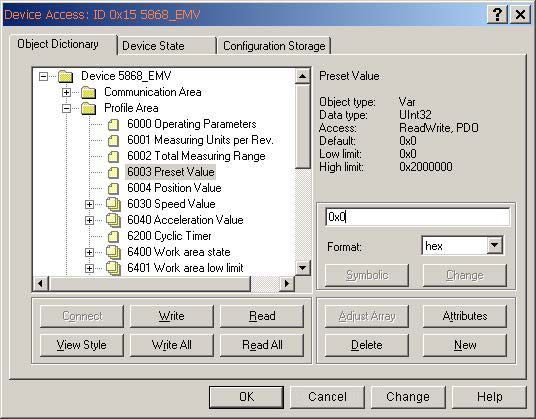
10 Application Programming Example  .  .  .  .  .  .  .  .  .  .  .  .  .  .  .  .  .  .  .  .  .  .  .  .  .  .  .  .  .  .  .  .  .  .  .  .  .  .  .  .  .  .  .  .  .  .  .  .  .  .  .  .  .  .  .  .  .  .  .  .  .  .  .  .  .  .  . 23
Setting Up Objects . . . . . . . . . . . . . . . . . . . . . . . . . . . . . . . . . . . . . . . . . . . . . . . . . . . . . . . . . . . . . . . . . . . . . . . . . . . . . . . . . . . . . . . . . . . . 23
    Total Measuring Range set to 3600 . . . . . . . . . . . . . . . . . . . . . . . . . . . . . . . . . . . . . . . . . . . . . . . . . . . . . . . . . . . . . . . . . . . . . . . . . 23
    Measuring Units per Revolution – limit to 3600 . . . . . . . . . . . . . . . . . . . . . . . . . . . . . . . . . . . . . . . . . . . . . . . . . . . . . . . . . . . . . 23
    Set Preset Value to 0 . . . . . . . . . . . . . . . . . . . . . . . . . . . . . . . . . . . . . . . . . . . . . . . . . . . . . . . . . . . . . . . . . . . . . . . . . . . . . . . . . . . . . . . 24
    Set the values of Transmit Parameters TPDO1 and TPDO2 . . . . . . . . . . . . . . . . . . . . . . . . . . . . . . . . . . . . . . . . . . . . . . . . . . . 24
    Producer Heartbeat - set to 500 ms  . . . . . . . . . . . . . . . . . . . . . . . . . . . . . . . . . . . . . . . . . . . . . . . . . . . . . . . . . . . . . . . . . . . . . . . . 25
    Set Work Area low and high limit values  . . . . . . . . . . . . . . . . . . . . . . . . . . . . . . . . . . . . . . . . . . . . . . . . . . . . . . . . . . . . . . . . . . . 25
    Save all modified parameters in the EEPROM Store Parameters 1010h . . . . . . . . . . . . . . . . . . . . . . . . . . . . . . . . . . . . . . . 26
    Object 1010h: Store Parameters  . . . . . . . . . . . . . . . . . . . . . . . . . . . . . . . . . . . . . . . . . . . . . . . . . . . . . . . . . . . . . . . . . . . . . . . . . . . 26
    Object 1011h: Load Standard Values . . . . . . . . . . . . . . . . . . . . . . . . . . . . . . . . . . . . . . . . . . . . . . . . . . . . . . . . . . . . . . . . . . . . . . . 26
Communication Profile – Further Objects . . . . . . . . . . . . . . . . . . . . . . . . . . . . . . . . . . . . . . . . . . . . . . . . . . . . . . . . . . . . . . . . . . . . . 27

11 Emergency Objects .  .  .  .  .  .  .  .  .  .  .  .  .  .  .  .  .  .  .  .  .  .  .  .  .  .  .  .  .  .  .  .  .  .  .  .  .  .  .  .  .  .  .  .  .  .  .  .  .  .  .  .  .  .  .  .  .  .  .  .  .  .  .  .  .  .  .  .  .  .  .  .  .  .  .  .  .  .  .  .  .  .  . 28

Error Codes Supported . . . . . . . . . . . . . . . . . . . . . . . . . . . . . . . . . . . . . . . . . . . . . . . . . . . . . . . . . . . . . . . . . . . . . . . . . . . . . . . . . . . . . . . . 28

12 Emergency Message .  .  .  .  .  .  .  .  .  .  .  .  .  .  .  .  .  .  .  .  .  .  .  .  .  .  .  .  .  .  .  .  .  .  .  .  .  .  .  .  .  .  .  .  .  .  .  .  .  .  .  .  .  .  .  .  .  .  .  .  .  .  .  .  .  .  .  .  .  .  .  .  .  .  .  .  .  .  .  .  .  . 29

Example of an Over-Temperature Message . . . . . . . . . . . . . . . . . . . . . . . . . . . . . . . . . . . . . . . . . . . . . . . . . . . . . . . . . . . . . . . . . . . . . 29
Emergency Protocol  . . . . . . . . . . . . . . . . . . . . . . . . . . . . . . . . . . . . . . . . . . . . . . . . . . . . . . . . . . . . . . . . . . . . . . . . . . . . . . . . . . . . . . . . . . 29

13 Heartbeat Protocol .  .  .  .  .  .  .  .  .  .  .  .  .  .  .  .  .  .  .  .  .  .  .  .  .  .  .  .  .  .  .  .  .  .  .  .  .  .  .  .  .  .  .  .  .  .  .  .  .  .  .  .  .  .  .  .  .  .  .  .  .  .  .  .  .  .  .  .  .  .  .  .  .  .  .  .  .  .  .  .  .  .  . 29

14 CAN open Object Dictionary .  .  .  .  .  .  .  .  .  .  .  .  .  .  .  .  .  .  .  .  .  .  .  .  .  .  .  .  .  .  .  .  .  .  .  .  .  .  .  .  .  .  .  .  .  .  .  .  .  .  .  .  .  .  .  .  .  .  .  .  .  .  .  .  .  .  .  .  .  .  .  .  .  . 30

Structure of the Entire Object Dictionary . . . . . . . . . . . . . . . . . . . . . . . . . . . . . . . . . . . . . . . . . . . . . . . . . . . . . . . . . . . . . . . . . . . . . . . 30

15 CANopen Communication Profile DS 301 V4.02 .  .  .  .  .  .  .  .  .  .  .  .  .  .  .  .  .  .  .  .  .  .  .  .  .  .  .  .  .  .  .  .  .  .  .  .  .  .  .  .  .  .  .  .  .  .  .  .  .  .  .  .  .  .  .  . 31

Communication Object  . . . . . . . . . . . . . . . . . . . . . . . . . . . . . . . . . . . . . . . . . . . . . . . . . . . . . . . . . . . . . . . . . . . . . . . . . . . . . . . . . . . . . . . 31
Manufacturer Specific Objects . . . . . . . . . . . . . . . . . . . . . . . . . . . . . . . . . . . . . . . . . . . . . . . . . . . . . . . . . . . . . . . . . . . . . . . . . . . . . . . . . 31

16 CANopen Encoder Device Profile DS 406 V3.2 .  .  .  .  .  .  .  .  .  .  .  .  .  .  .  .  .  .  .  .  .  .  .  .  .  .  .  .  .  .  .  .  .  .  .  .  .  .  .  .  .  .  .  .  .  .  .  .  .  .  .  .  .  .  .  .  .  . 32

Device-Specific Objects . . . . . . . . . . . . . . . . . . . . . . . . . . . . . . . . . . . . . . . . . . . . . . . . . . . . . . . . . . . . . . . . . . . . . . . . . . . . . . . . . . . . . . . 32

17 Objects in Detail - Encoder Profile DS 306 V3.2.17-32 .  .  .  .  .  .  .  .  .  .  .  .  .  .  .  .  .  .  .  .  .  .  .  .  .  .  .  .  .  .  .  .  .  .  .  .  .  .  .  .  .  .  .  .  .  .  .  .  .  .  . 33

Object 6000H Operating Parameters . . . . . . . . . . . . . . . . . . . . . . . . . . . . . . . . . . . . . . . . . . . . . . . . . . . . . . . . . . . . . . . . . . . . . . . . . . . 33
Object 6001H: Measuring Steps Per Revolutions (Resolution) . . . . . . . . . . . . . . . . . . . . . . . . . . . . . . . . . . . . . . . . . . . . . . . . . . . 33
Object 6002H: Total Number of Measuring Steps . . . . . . . . . . . . . . . . . . . . . . . . . . . . . . . . . . . . . . . . . . . . . . . . . . . . . . . . . . . . . . . 34
Object 6003H: Preset Value . . . . . . . . . . . . . . . . . . . . . . . . . . . . . . . . . . . . . . . . . . . . . . . . . . . . . . . . . . . . . . . . . . . . . . . . . . . . . . . . . . . . 34
Object 6004H: Position Value . . . . . . . . . . . . . . . . . . . . . . . . . . . . . . . . . . . . . . . . . . . . . . . . . . . . . . . . . . . . . . . . . . . . . . . . . . . . . . . . . . 34
Object 6030H: Speed Value . . . . . . . . . . . . . . . . . . . . . . . . . . . . . . . . . . . . . . . . . . . . . . . . . . . . . . . . . . . . . . . . . . . . . . . . . . . . . . . . . . . . 35
Object 6200H: Cyclic Timer . . . . . . . . . . . . . . . . . . . . . . . . . . . . . . . . . . . . . . . . . . . . . . . . . . . . . . . . . . . . . . . . . . . . . . . . . . . . . . . . . . . . 35
Object 6500H: Display Operating Status  . . . . . . . . . . . . . . . . . . . . . . . . . . . . . . . . . . . . . . . . . . . . . . . . . . . . . . . . . . . . . . . . . . . . . . . 35
Object 6503H: Alarms . . . . . . . . . . . . . . . . . . . . . . . . . . . . . . . . . . . . . . . . . . . . . . . . . . . . . . . . . . . . . . . . . . . . . . . . . . . . . . . . . . . . . . . . . 36
Object 6504H: Supported Alarms . . . . . . . . . . . . . . . . . . . . . . . . . . . . . . . . . . . . . . . . . . . . . . . . . . . . . . . . . . . . . . . . . . . . . . . . . . . . . . 36
Object 6505H: Warnings . . . . . . . . . . . . . . . . . . . . . . . . . . . . . . . . . . . . . . . . . . . . . . . . . . . . . . . . . . . . . . . . . . . . . . . . . . . . . . . . . . . . . . . 37
Object 6506H: Supported Warnings  . . . . . . . . . . . . . . . . . . . . . . . . . . . . . . . . . . . . . . . . . . . . . . . . . . . . . . . . . . . . . . . . . . . . . . . . . . . 37
Object 6400H: Working Area State Register  . . . . . . . . . . . . . . . . . . . . . . . . . . . . . . . . . . . . . . . . . . . . . . . . . . . . . . . . . . . . . . . . . . . . 38
Object 6401H: Working Area Low Limit  . . . . . . . . . . . . . . . . . . . . . . . . . . . . . . . . . . . . . . . . . . . . . . . . . . . . . . . . . . . . . . . . . . . . . . . . 38
Object 6402H: Working Area High Limit . . . . . . . . . . . . . . . . . . . . . . . . . . . . . . . . . . . . . . . . . . . . . . . . . . . . . . . . . . . . . . . . . . . . . . . . 38
Object 2100H: Baud Rate . . . . . . . . . . . . . . . . . . . . . . . . . . . . . . . . . . . . . . . . . . . . . . . . . . . . . . . . . . . . . . . . . . . . . . . . . . . . . . . . . . . . . . 38

       4             Turck Inc. | 3000 Campus Drive, Minneapolis, MN 55441 | T +1 800 544 7769 | F +1 763 553 0708 | www.turck.com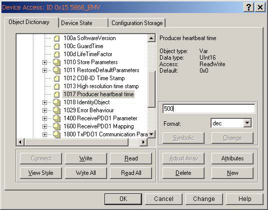
Object 2101H: Node address  . . . . . . . . . . . . . . . . . . . . . . . . . . . . . . . . . . . . . . . . . . . . . . . . . . . . . . . . . . . . . . . . . . . . . . . . . . . . . . . . . . 39
Object 2102H: CAN Bus Terminations OFF/ON . . . . . . . . . . . . . . . . . . . . . . . . . . . . . . . . . . . . . . . . . . . . . . . . . . . . . . . . . . . . . . . . . . 39
Object 2103H: Firmware Flash Version . . . . . . . . . . . . . . . . . . . . . . . . . . . . . . . . . . . . . . . . . . . . . . . . . . . . . . . . . . . . . . . . . . . . . . . . . 39
Object 2105H: Save All Bus Parameters  . . . . . . . . . . . . . . . . . . . . . . . . . . . . . . . . . . . . . . . . . . . . . . . . . . . . . . . . . . . . . . . . . . . . . . . . 40
Object 2140H: Customer Memory (16 Bytes) . . . . . . . . . . . . . . . . . . . . . . . . . . . . . . . . . . . . . . . . . . . . . . . . . . . . . . . . . . . . . . . . . . . 40
Object 1029H: Error Behavior . . . . . . . . . . . . . . . . . . . . . . . . . . . . . . . . . . . . . . . . . . . . . . . . . . . . . . . . . . . . . . . . . . . . . . . . . . . . . . . . . . 40

18 Network Management .  .  .  .  .  .  .  .  .  .  .  .  .  .  .  .  .  .  .  .  .  .  .  .  .  .  .  .  .  .  .  .  .  .  .  .  .  .  .  .  .  .  .  .  .  .  .  .  .  .  .  .  .  .  .  .  .  .  .  .  .  .  .  .  .  .  .  .  .  .  .  .  .  .  .  .  .  .  .  . 41

19 NMT Commands .  .  .  .  .  .  .  .  .  .  .  .  .  .  .  .  .  .  .  .  .  .  .  .  .  .  .  .  .  .  .  .  .  .  .  .  .  .  .  .  .  .  .  .  .  .  .  .  .  .  .  .  .  .  .  .  .  .  .  .  .  .  .  .  .  .  .  .  .  .  .  .  .  .  .  .  .  .  .  .  .  .  .  .  .  . 42

20 LED States  .  .  .  .  .  .  .  .  .  .  .  .  .  .  .  .  .  .  .  .  .  .  .  .  .  .  .  .  .  .  .  .  .  .  .  .  .  .  .  .  .  .  .  .  .  .  .  .  .  .  .  .  .  .  .  .  .  .  .  .  .  .  .  .  .  .  .  .  .  .  .  .  .  .  .  .  .  .  .  .  .  .  .  .  .  .  .  .  .  .  . 43

21 Definitions .  .  .  .  .  .  .  .  .  .  .  .  .  .  .  .  .  .  .  .  .  .  .  .  .  .  .  .  .  .  .  .  .  .  .  .  .  .  .  .  .  .  .  .  .  .  .  .  .  .  .  .  .  .  .  .  .  .  .  .  .  .  .  .  .  .  .  .  .  .  .  .  .  .  .  .  .  .  .  .  .  .  .  .  .  .  .  .  .  .  . 44

22 Abbreviations Used .  .  .  .  .  .  .  .  .  .  .  .  .  .  .  .  .  .  .  .  .  .  .  .  .  .  .  .  .  .  .  .  .  .  .  .  .  .  .  .  .  .  .  .  .  .  .  .  .  .  .  .  .  .  .  .  .  .  .  .  .  .  .  .  .  .  .  .  .  .  .  .  .  .  .  .  .  .  .  .  .  .  . 44

23 Decimal-Hexadecimal Conversion Table .  .  .  .  .  .  .  .  .  .  .  .  .  .  .  .  .  .  .  .  .  .  .  .  .  .  .  .  .  .  .  .  .  .  .  .  .  .  .  .  .  .  .  .  .  .  .  .  .  .  .  .  .  .  .  .  .  .  .  .  .  .  . 45

24 Glossary .  .  .  .  .  .  .  .  .  .  .  .  .  .  .  .  .  .  .  .  .  .  .  .  .  .  .  .  .  .  .  .  .  .  .  .  .  .  .  .  .  .  .  .  .  .  .  .  .  .  .  .  .  .  .  .  .  .  .  .  .  .  .  .  .  .  .  .  .  .  .  .  .  .  .  .  .  .  .  .  .  .  .  .  .  .  .  .  .  .  .  .  . 46

                                                                                                                                                                                                                                                                                                       5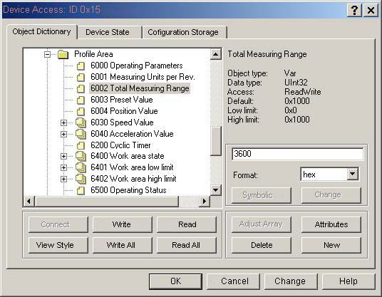
1 General
CANopen Singleturn Encoder Series RS-52/RS-53
The CANopen encoder of Series RS-52/RS-53 support the latest CANopen communication profile according DS 301 V4.02 . In addi-
tion a device-specific encoder profile DS 406 V3.1 is implemented.

The following operating modes can be selected: Polled Mode, Cyclic Mode, Sync Model. Moreover, scale factors, preset values,
limit switch values and many other additional parameters can be programmed via the CAN-Bus. At Power ON all parameters are
loaded from an EEPROM, which had previously been saved in the non-volatile memory to protect them in case of power failure.
The following output values may be freely combined as PDO (PDO Mapping): position, speed as well as the status of the two limit
switches, alarms and warnings.

The encoders are available with a connector or a cable connection - all changes to the device address and baud rate are software
controlled.

One LED located on the back indicate the operating or fault status of the CAN bus, as well as the status of an internal diagnostic.
CANopen encoders are available in blind hollow shaft and solid shaft versions, and are ideal for use in harsh industrial
environments thanks to their IP67/IP69K protection rating.

The CANopen Communication Profile DS 301 V4.02
CANopen represents a unified user interface and thus allows for a simplified system structure with a wide variety of devices.
CANopen is optimized for the fast exchange of data in real-time systems and possesses a number of different device profile
that have been standardized. The CAN in Automation (CiA) manufacturers and users group is responsible for creating and
standardization of the relevant profiles.

CANopen offers:
 • user-friendly access to all device parameters
 • auto-configuration of the network and of the devices
 • device synchronization within the network
 • cyclic and event-driven process data exchange
 • simultaneous read and write of data

CANopen uses four communication objects (COB) with different properties:
 • Process Data Objects (PDO) for real-time data
 • Service Data Objects (SDO) for transmitting parameters and programs
 • Network Management (NMT, Life-Guarding, Heartbeat)
 • Predefined Objects (for Synchronization, Time-Stamp, Emergency)

All device parameters are filed in an Object Dictionary. This Object Dictionary contains the description, data type and structure of
the parameters, as well as the address (Index).
The dictionary is divided into a communications profile section, a section covering the device profile as well as a section specific to
the manufacturer.

Encoder Device Profile DS 406 V3.1

This profile describes a vendor-independent mandatory definition of the interface with regard to encoders. It is laid down in the
profile, which CANopen functions are to be used as well as how they are to be used. This standard thus makes possible an open
vendor-independent bus system. The device profile is broken down into two Object classes:
                  Physical position

 Class C1          Basic Function             •     Class C1 describes all the basic functions that the encoder must contain
                                              •     Class C2 contains numerous extended functions, which must either be
                 Absolute position                supported by encoders of this class (Mandatory) or which are optional. Class
                                                  2 devices thus contain all C1 and C2 mandatory functions, as well as additional
 Class C2         Scaling function                optional functions dependent on the manufacturer. An address range is also
                                                  defined in the profile to which the manufacturer’s own special functions can
 Class C2         Preset function                 be assigned.

               Output position value

   6        Turck Inc. | 3000 Campus Drive, Minneapolis, MN 55441 | T +1 800 544 7769 | F +1 763 553 0708 | www.turck.com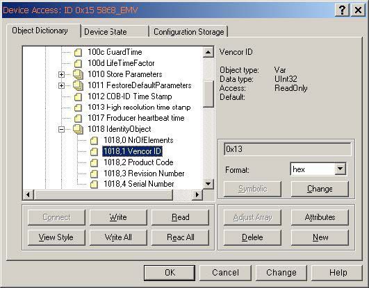
Objectives of LSS

CiA DSP 305 CANopen Layer Setting Service and Protocol (LSS) services and protocols were created to enable the following
parameters to be read and changed through the network:

  • The CANopen Node ID
  • The CAN baud rate
  • The LSS address
This increases the “plug–and-play” capabilities of devices on CANopen networks as preconfiguration of the network is less
restrictive. The LSS Master is responsible for configuring these parameters on one or more LSS Slaves on a CANopen network.

Data transmission

With CANopen data are transferred via two different communication types (COB=Communication
Object) with different properties:

  • Process Data Objects (PDO – real-time capable)
  • Service Data Objects (SDO)

The Process Data Objects (PDO) provide high-speed exchange of real-time data (e.g. encoder position, speed, comparative posi-
tion status) with a maximum length of 8 byte. These data are transmitted with a high priority (low COB-Identifier). PDOs are broad-
cast messages and provide their real-time data simultaneously to all desired receivers. PDOs can be mapped, i.e. 4 byte of position
and 2 byte of speed can be combined in one 8 byte data word.

The Service Data Objects (SDO) form the communication channel for the transfer of device parameters (e.g. encoder resolution
programming). As these parameters are transmitted acyclically (e.g. only once during boot-up of the network), the SDO objects
have a low priority (high COB-Identifier).

Objects and Function Code in the Predefined Connection Set                                     Bit-No.: COB-Identifier
                                                                            10						0
For easier management of the Identifiers CANopen
uses the “Predefined Master/Slave Connection Set”,
where all identifiers are defined with standard values
in the object dictionary. These identifiers can
however be changed and customized via SDO access.

                                                                       Function Code			Node-ID

The 11-bit Identifier is made up of a 4-bit function code and a 7-bit node-ID number.

                                                              Note:
                                The higher the value of the COB-Identifier, the lower is its priority!

Broadcast (network-wide) Objects

                                          Function code                                                  Communication Parameters
 Object                                                                     Resulting COB-ID
                                             (binary)                                                           at Index
 NMT                                           0000                                0                                -
 SYNC                                          0001                            128 (80h)                    1005h, 1006, 1007h
 TIME STAMP                                    0010                            256 (100h)                      1012h, 1013h

                                                                                                                                 7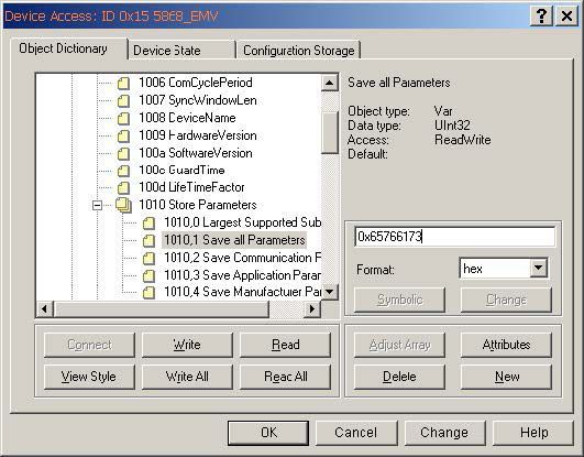
Peer-To Peer (device-to-device) Objects

                                                  Function code                                                             Communication Parameters
Object                                                                                  Resulting COB-ID
                                                     (binary)                                                                      at Index
EMERGENCY                                               0001                          129 (8th) - 255 (FFh)                       1014h, 1015h
PDO1 (tx)                                               0011                        385 (181h) - 511 (1FFh)                          1800h
PDO1 (rx)                                               0100                        513 (201h) - 639 (27Fh)                          1400h
PDO2 (tx)                                               1010                        641 (281h) - 767 (2FFh)                          1801h
PDO2 (rx)                                               0110                        769 (301h) - 895 (37Fh)                          1401h
PDO3 (tx)                                               0111                        897 (381h) - 1023 (3FFh)                         1802h
PDO3 (rx)                                               1000                       1025 (401h) - 1151 (47Fh)                         1402h
PDO4 (tx)                                               1001                       1153 (481h) - 1279 (4FFh)                         1803h
PDO4 (rx)                                               1010                       1281 (501h) - 1407 (57Fh)                         1403h
SDO (tx)                                                1011                       1409 (581h) - 1535 (5FFh)                         1200h
SDO (rx)                                                1100                       1537 (601h) - 1663 (67Fh)                         1200h
NMT Error Control                                       1110                       1793 (701h) - 1919 (77Fh)                      1016h, 1017h

Restricted, reserved Objects

               COB-ID                            Used by object
              0 (000h)                                  NMT
              1 (001h)                               reserved
       257 (101h) - 384 (180h)                       reserved
   1409 (581h) - 1535 (5FFh)                     default SDO (tx)
   1537 (601h) - 1663 (67Fh)                     default SDO (rx)
            1760 (6E0h)                              reserved
   1793 (701h) - 1919 (77Fh)                    NMT Error Control
   2020 (780h) - 2047 (7FFh)                         reserved

   8        Turck Inc. | 3000 Campus Drive, Minneapolis, MN 55441 | T +1 800 544 7769 | F +1 763 553 0708 | www.turck.com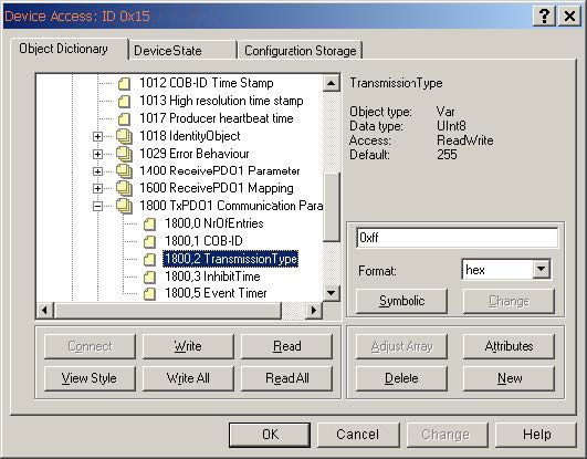
2 Transmission of Process Data
Within the CANopen encoder three PDO services PDO1 (tx) , PDO2 (tx) and PDO3(tx) are available.
A PDO transmission can be triggered by a variety of events (see Object Dictionary Index 1800h):

  • asynchronously (event driven) by an internal cyclic device timer or by a change in the process value of the sensor data
  • synchronously as a response to a SYNC telegram; (a SYNC command will cause all CANopen nodes to store their values
    synchronously, after which they are transferred in succession to the bus according to their set priority)
  • as a response to an RTR-Telegram (per Remote Frame=recessive RTR-bit, exactly that message with the communicated ID will
    be requested)

Example: Default Mapping of the PDO messages have the following structure

 Mapping                             TPDO1 1800h                           TPDO2 1801h                 TPDO3 1802h
 Mapping object                      1A00h                             1A01h                           1A02h
 Content                             0x60040020                        0x60040020                      0x60300110
 Object                              6004h                                 6004h                       6030h
 Subindex                            00                                    00                          01
 Length                              20h(32 Bit)                       20h(32 Bit)                     10h(16 Bit)
                                     Asynchronous                      Synchronous                     Asynchronous

Transmit PDO 1 (1800h) Position asynchronous

Default COB-ID is 180 + Node number: e.g. 180h + 3Fh = 1BFh

 Message                    Byte 0                          Byte 1                   Byte2                     Byte 3
 1BF                        Position LSB                    Position MSB             00                        00

Transmit PDO2 (1802h) Position synchronous (SYNC-Mode)

Default COB-ID is 280 + Node number: e.g. 280h + 3Fh = 2BFh

Message Byte 0 Byte 1 Byte2 Byte 3
2BF Position LSB Position MSB 00 00

Position values are in a range of 0 – 3FFFh oder 0 – 16383 (decimal).

Transmit PDO3 (1801h) Velocity asynchronous

Default COB-ID is 380 + Node number: e.g. 380h + 3Fh = 3BFh

 Message                                           Byte 0                                    Byte 1
 3BF                                               Velocity LSB                              Velocity MSB

The value of the velocity is signed and is shifted in a range of (plus) 0 – 1A00h resp (minus) 0 – E600h

                                                                                                                        9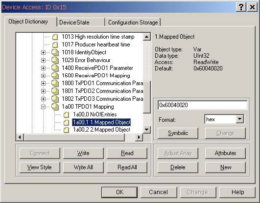
3 Transmission of Service Data
SDO-COB-ID

The following identifiers are available as standard for the SDO services:

SDO (tx) (Encoder ‐› Master): 580h (1408) + node number
SDO (rx) (Master ‐› Encoder): 600h (1536) + node number

The SDO identifiers cannot be changed!

        Command
    (Expedited Protocol)         Type                                           Function
            22h                  SDO(rx), Initiate Download Request             Send parameters to encoder (max. data length 4 byte)
            23h                  SDO(rx), Initiate Download Request             Send parameters to encoder (data length 4 byte)
            2Bh                  SDO(rx), Initiate Download Request             Send parameters to encoder (data length 2 byte)
            2Fh                  SDO(rx), Initiate Download Request             Send parameters to encoder (data length 1 byte)
            60h                  SDO(tx), Initiate Download Request             Acknowledgment of receipt by Master
            40h                  SDO(rx), Initiate Download Request             Request of parameters from encoder
            43h                  SDO(tx), Initiate Download Request             Parameters to Master, data length = 4 byte (unsigned 32)
            4Bh                  SDO(tx), Initiate Download Request             Parameters to Master, data length = 2 byte (unsigned 16)
            4Fh                  SDO(tx), Initiate Download Request             Parameters to Master, data length = 1 byte (unsigned 8)
            80h                  SDO(tx), Initiate Download Request             Encoder sends an error code to Master

                                                              Note:
 If an error occurs, then an error message (command 80h) will replace the normal confirmation (Response). The error message
 covers not only the communication protocol error but also the object dictionary access error (e.g. wrong index, attempted write
 to Read-Only Object, incorrect data length etc).
 The error codes are described in the CANopen Profile (DS 301) or in the Device Profile (DSP 406).

   10     Turck Inc. | 3000 Campus Drive, Minneapolis, MN 55441 | T +1 800 544 7769 | F +1 763 553 0708 | www.turck.com
Example: Transmission of Service Data to and from the encoder
Master Encoder
Parameters to
encoder
ID COB for Command Index Sub-Index Max. 4 byte
SDO (rx) 22h Data
Acknowledgement of
ID COB for Command Index Sub-Index receipt from encoder
SDO (rx) 60h
Master Encoder
Request to encoder
Emission of data by
encoder
LSS Hardware Restrictions (LSS Address)
All LSS Slaves must support valid Object Dictionary entries for Identity object [1018h] which has 32 bits
for each part of the LSS Address:
• Vendor-ID (numerical number)
• Product-Code (numerical number)
• Revision-Number (major an minor revision as numerical number)
• Serial-Number (numerical number)
• LSS-Master CAN-ID 2021
• LSS-Slave CAN-ID 2020
A Product-Code, Revision-Number and a Serial-Number are assigned by the device supplier. The LSS
address which must be absolutely unique. No other LSS slave may have the same LSS address.
LSS Operating Restrictions
To function properly the following restrictions apply:
• All devices on a CANopen network must support LSS.
• There can be only one LSS Master.
• All nodes are required to start-up with the same initial baud rate.
• LSS communication can take place during any NMT state such as “stopped” or “pre-operational”.
LSS Configuration and the Operation Modes
Configuration Mode
• When an LSS Slave is in this mode, it actively listens for and processes configuration command from the LSS Master.
• Some configuration commands configure only one LSS Slave at the time (for example, to change of CANopen node ID)
• Some configuration commands configure multiple or all LSS Slave nodes (for example, to change the baud rate)
Operation Mode
• A LSS Slave in this mode ignores the configuration commands from the LSS
11ed
4 Power supply and CAN-bus connection
Power supply
Sensor: Magnetic Hall -Sensor 14 Bit Resolution /9 Bit Accuracy
anCable terminal Power supply: 10...30 VDC
ccuracy
Current consumption: typ. 22mA at 24 VDC max. 49 mA at 10 VDC
hort name Description Cable color
Reverse polarity protection: yes
CAN Transceiver: 82C251 / short circuit tested
G
sted CAN Ground gray
Galvanic Isolation: no
L CAN_Low () yellow
H CAN_High (+) CANopen Communication
green DS 301 V4.02
V 0Volt power white
CANopen Encoder Device Profile DS406 V 3.1
V +UB power brown
CAN
CanCable - Cable terminal
terminal
Short name Description Cable color Short name Description Cable color
CG CAN Ground gray
CL CAN_Low () yellow CG CAN Ground gray
CH CAN_High (+) green
hort name
0V Description
0Volt power white PIN Nr. Color CL CAN_Low (-) yellow
+V +UB power brown CH CAN_High (+) green
G CAN Ground 1 GY 0V 0 Volt power white
L CAN_Low () 5 YE +V +UB power brown
HShort name CAN_High (+) 4 GN
Description PIN Nr. Color
V CAN - M12 Connector
0 Volt power 3 WH
VCG CAN+UB
Groundpower
1 2
GY BN Short name Description PIN Number.
CL CAN_Low () 5 YE
erminal
CH M12Connector
CAN_High (+) 4 GN
0V 0 Volt power 3 WH CG CAN Ground 1
+V +UB power 2 3 BN
4
Terminal M12Connector 5
CL CAN_Low (-) 5
1 2 CH CAN_High (+) 4
0V 0 Volt power 3
+V +UB power 2
Mechanical characteristics
IP69K protection on the flange side, robust Mechanical Characteristics:
bearing assemblies with interlocking Max. speed: 6000 min -1
bearings, mechanically protected shaft seal.
Starting torque < 0,06 Nm
Weight: approx. 0,2 kg
Protection acc. to EN 60 529: IP 67 (IP 69k on request)
Working temperature: -40°C...+85°C
Materials: Shaft: stainless steel, Flange: aluminum,
Housing: die cast zinc, Cable: PUR
Shock resistance acc. to DIN-IEC 68-2-227: 5000 m/s2, 6 ms
Vibration resistance acc. to DIN-IEC 68-2-6: 300 m/s2, 10...2000 Hz
Permanent shock resistance acc. to DIN-IEC 1000 m/s2, 2 ms
511 of 45
68-2-29:
Fully encapsulated electronics, seperate Vibration (broad-band random) to DIN-IEC 5...2500 Hz, 100 m/s2 - rms
mechanical bearing assembly 68-2-64:
12 511 of MN
Turck Inc. | 3000 Campus Drive, Minneapolis, 4555441 | T +1 800 544 7769 | F +1 763 553 0708 | www.turck.com5 Initial Start up - General Device Settings
It is possible to change the baud rate using the Software at Object 2100h or one of the appropriate LSS-Services. The following
baud rates are available to the user:
Value Baudrate in Kbits
Factory default: 250 kBit/s (value 5)
0 10 Please note the following when selecting a baud rate
1 20 The chosen cycle time (see Object 1800h,Sub-index 5 Event Timer) must be longer
than the bus transfer time, to ensure that the PDOs are communicated error-free!
2 50
3 100
4 125
5 250
6 500
8 1000
Note:
With a baud rate of 10 KBaud: cycle time must be at least 14 ms
With a baud rate of 20 KBaud: cycle time must be at least 10 ms
With a baud rate of 50 KBaud: cycle time must be at least 4 ms
With a cycle time=0 in Event-Mode (i.e. PDO on value change) the baud rate must be at least 125 KBaud.
Node number
It is possible to change the node number using the Software at Object 2101h or one of the appropriate
LSS-Services.
Factory default : 0x3F (63 decimal).
Node number 0 is reserved and must not be used by any node. The resulting node numbers lie in the range 1...7Fh hexadecimal
(1...127 decimal).
Note:
The acceptance of a new node number only becomes effective when the encoder is rebooted (Reset/Power-on) or by means
of an NMT Reset Node command. All previous adjustments made to the object directory are lost and are setting to the factory
default.
CAN-BUS Termination
The CAN-Bus Termination can changed in Object 2102h .
Factory default: 0x01 (Bus termination active)
Once the CAN bus has been looped through, it must be terminated between CAN+ and CAN- at both ends using 120 ohm bus
termination resistors.
Save All Bus Parameters
The “save all bus parameters” can changed in Object 2105h..
Factory default: 0x65766173 (“save”)
This object stores all bus parameters (Object 2100h ,2101h,2102h) permanently in an EEprom. Using the command “save” (save
all Parameters) causes all the parameters to be stored. This process requires ca. 5ms. In order to prevent an inadvertent save, the
instruction will only be executed if the string “save” is entered as a codeword into this Sub-Index.
Note:
The Parameter “save“ (hexadecimal 0x65766173) stores all bus adjustments as Baudrate, Node number and Termination
permanently.
136 Layer Setting Services (LSS) Exactly two conditions must be fulfilled for the interconnection of CANopen devices to a network: all devices must use the same Baudrate, and the CANopen Node-IDs must be unique. The condition for the use of the LSS is, in addition to support by the device itself, to establish a 1:1 wiring to the Node. Then the Baudrate and the Node-ID are set in dialog mode. The COB-ID 0x7E5 is used for CAN messages to the device, the device responds to COB-ID 0x7E4. LSS messages are always a full 8 bytes long. Unused bytes are reserved and should be initialized with 0. To make contact with a device to be configured, the “Switch Mode Global” command is transmitted: 0x04 0x01 reserved This command sets the device to LSS configuration mode. Unfortunately, this very service is the only unacknowledged LSS service, to which the device will therefore not respond, even if it has carried it out. The system integrator can therefore only find out with the following command whether the device has reacted. Next the Node-ID is requested via the “Inquire Node-ID” service: 0x5E reserved If successful, the device responds with: 0x5E Node ID reserved If there is no response, then either the device does not support the LSS service or the Baudrate is not correct. If, namely, the Bau- drate when supplied is not known, the above-mentioned communication sequence must be tested with all permissible CANopen Baudrates until the device is found. The “Configure Node-ID” service is used to configure the new Node-ID: 0x11 NodeID reserved The error code is included in the device response: 0x11 Error code Error extension reserved Error code 0 means success; error code 1 means inadmissible Node-ID; the other error codes are reserved. The error extension contains vendor-specific information but is only valid for error code 0xFF. The Baudrate is configured with the “Configure Bit Timing Parameters” service: 0x13 Bit timing Table entry reserved 14 Turck Inc. | 3000 Campus Drive, Minneapolis, MN 55441 | T +1 800 544 7769 | F +1 763 553 0708 | www.turck.com
The standardized CANopen Baudrates are listed in the following table:

 Baudrate table 0x00
 Table index                                                     Baudrate
 0                                                               1000 kBit/s
 1                                                               800 kBit/s
 2                                                               500 kBit/s
 3                                                               250 kBit/s
 4                                                               125 kBit/s
 5                                                               reserved
 6                                                               50 kBit/s
 7                                                               20 kBit/s
 8                                                               10 kBit/s

Again the device response is:

 0x13                            Error code                      Error extension                  reserved

Error code 0 means success; error code 1 means inadmissible baudrate; the other error codes are reserved. The error extension
contains vendor-specific information, but is only valid for error code 0xFF.

Now that the node-ID and the baudrate are configured, these settings should be saved with the “Store Configuration” service:

 0x17                                                                                             reserved

Whereupon the device acknowledges:

 0x17                            Error code                      Error extension                  reserved

Error code 0 means success; error code 1 means that the device does not support saving; error code 2 means that there is a
problem with access to the storage medium; the other error codes are reserved. The error extension contains vendor-specific
information, but is only valid for error code 0xFF.

Finally, the device is switched back from configuration mode to normal mode via “Switch Mode Global”:

 0x04                                             0x00                                            reserved

After being switched physically off and on again, the device now works with the new settings.

                                                                                                                               15
7 Default settings on delivery
On delivery the following software parameters have been factory set.
Description Setting Software
Baud rate 250 Kbit/s Object 2100h = 05h
Node address 63 Object 2101h = 3Fh
Termination ON Object 2102h = 01h
Index (hex) Name Standard value
Communication parameter
1005h COB-ID Sync 80h
100Ch Guard Time 0
100Dh Life Time Factor 0
1012h COB-ID Time stamp 100h
1013h High Resolution time stamp 0
1017h Producer heartbeat time 0
1029h Error Behavior 0 = Comm Error
1 = Device specific
1 = Manufacturer Err.
1800h TPDO1 Communication Parameter
01h COB-ID 180h + Node number
02h Transmission Type 255 (asynch)
03h Inhibit Time 0 [steps in 100Ts]
05h Event timer 0 [steps in ms]
1801h TPDO3 Communication Parameter
01h COB-ID 280h + Node number
02h Transmission Type 1 (synch)
03h Inhibit Time 0 [steps in 100Ts]
05h Event timer 0 [steps in ms]
1802h TPDO2 Communication Parameter
01h COB-ID 380h + Node number
02h Transmission Type 255 (asynch)
03h Inhibit Time 0 [steps in 100Ts]
05h Event timer 0 [steps in ms]
1A00h TPDO1 Mapping
01h 1.Mapped Object 0x60040020
1A01h TPDO3 Mapping
01h 1.Mapped Object 0x60040020
1A02h TPDO2 Mapping
01h 1.Mapped Object 0x60300110
16 Turck Inc. | 3000 Campus Drive, Minneapolis, MN 55441 | T +1 800 544 7769 | F +1 763 553 0708 | www.turck.comIndex (hex) Name Standard value
Encoder Profile
6000h Operating Parameter Scaling off
6001h Measuring Units per Revolution 16384 (14 Bit)
6002h Total Measuring Range 16384 (14 Bit)
6003h Preset value 0
6200h Cyclic Timer (see TPDO1 Comm.Par) 0
6401h Work area low limit 0
6402h Work area high limit 16383
2100h Baud rate 05h
2101h Node number 3Fh
2102h CANbus termination 1 (active)
2105h Save All Bus Parameters 0x65766173
Note:
The original Standard Values (default values on delivery) can be reloaded again by means of Object 1011h (restore parameters).
In order to ensure that parameter changes are saved in the event of power failure, then these must without fail be transferred
to the EEPROM by means of Object 1010h (store parameters). This will cause all data already present in the EPROM to be over-
written!
WARNING:
If errors have occurred during programming of the objects and if these parameters are then saved in the EEPROM, it will not be
possible to address the encoder next time it is switched on (the encoder will send only Emergency messages).
This error can be cleared only by means of a general Reset of the encoder.
178 Communication Parameters The COB-ID and the Transmission Type for PDO1 are defined in the Object Dictionary Index 1800h . Default-settings: Enabling: PDO enabled RTR allowed COB-ID: 180h + node number set (here 11h) Transmission type: 255 = asynchronous acc. to device profile Event Timer: 20 ms 18 Turck Inc. | 3000 Campus Drive, Minneapolis, MN 55441 | T +1 800 544 7769 | F +1 763 553 0708 | www.turck.com
The COB-ID and the Transmission Type for PDO2 are defined in the Object Dictionary Index 1800h .

Defaults:
   Enabling:              PDO enabled          RTR allowed
   COB-ID:                180h + node number set (here 11h)
   Transmission type:     255 = asynchronous acc. to device profile
   Event Timer:           20 ms

                                                                                                   19
Definition of the Transmission type of the PDO
transmission type PDO transmission
cyclic acyclic synchronous asynchronous RTR only
0 X X
1-240 X X
241-251 - reserved -
252 X X
253 X X
254 X
255 X
A value between 1 ...240 means that the PDO will be sent synchronously and cyclically. The number of the Transmission Type signi-
fies the quantity of SYNC pulses that are necessary to forward the PDOs.
The Transmission Types 252 and 253 state that the PDO will only be sent when requested via an RTR.
Note:
Type 254 means that the event will be triggered depending on the application (application-specific), whereas Type 255 is
dependent on the device (device-specific). Additionally for Numbers 254/255 a time-controlled EventTimer can be used. The
values for the timer can range from 1ms ... 65535 ms.
Variable PDO Mapping
Variable Mapping of the various objects means that the user is able to configure the content of the Transmit PDOs dependent on
the application.
Example of an entry in the Mapping Table:
The mapped PDO consists of 3 Application Object entries of varying lengths:
Application Object 2 occupies Byte 1 (08h) in the Transmit PDO. Thereafter follows Application Object 3 with a length of 16 bit
(10h = 2 bytes) and finally Application Object 1 with a length of 1 byte. In total, 32 bits are occupied in this PDO.
20 Turck Inc. | 3000 Campus Drive, Minneapolis, MN 55441 | T +1 800 544 7769 | F +1 763 553 0708 | www.turck.comStructure of a Mapping entry
The Mapping Object for PDO 1 is defined in the Object Dictionary Index 1A00h. It consists of 2 entries and can be modified by the
user (variable mapping).
Byte: MSB LSB
Index (16 bit) sub-index (8 bit) object length (8 bit)
The default setting for the Mapping of the Transmit PDO:
Mapping TPDO1 TPDO2 TPDO3
1.Mapping 0x60040020 0x60040020 0x60300110
Object 6004h 6004h 6030h
Subindex 00 00 01
Data length 20h(32 Bit) 20h(32 Bit) 10h(16 Bit)
Asynchron Synchron Asynchron
The CANopen encoder supports variable mapping on all 3 Transmit PDOs.
219 Example off a variable Mapping table
Mapping Object 1A00h
The Mapping Object 1A00h describes the 1.Transmit PDO. It is possible to map as much as objects, until the maximum data length
of 8 Bytes is reached.
The Objects 1A01h of Transmit PDO2 and 1A02h of Transmit PDO3 following the input of PDO1.
Mapping table of Object 1A00h:
Mapping TPDO1 Mapping TPDO1 Mapping TPDO1 Mapping
Subindex 00 01 02
Content Nr.of Entries 1.Mapped Object 2.Mapped Object
Object 2 6004h 6030h
Subindex 00 01
Length Byte 20h(32 Bit) 10h(16 Bit)
Asynchronous Asynchronous
Encoder Profile - Device specific Objetcs
In this example two Objects are mapped to the 1.Transmit PDO at 1800h
22 Turck Inc. | 3000 Campus Drive, Minneapolis, MN 55441 | T +1 800 544 7769 | F +1 763 553 0708 | www.turck.com10 Application Programming Example:
Setting up Objects
• Total Measuring Range to 3600
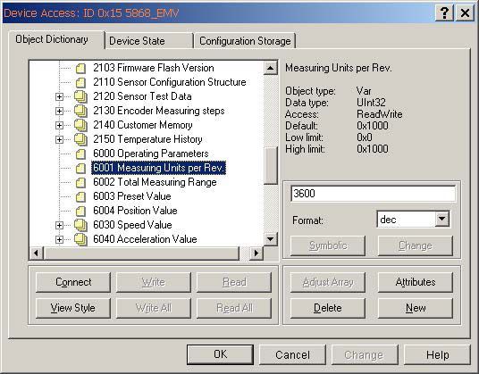
• Measuring Units per Revolution should be set to 3600 steps per revolution
• Position Value should be set to 0
• TPDO1 (Position) should transmit the event every 10 ms
• TPDO2 (Speed) should transmit the event every 20 ms
• Producer Heartbeat should be reduced to 500 ms
• Work area limits are 1000 and 3500
• The new parameters should be saved in the EEPROM
Total Measuring Range set to 3600
Measuring Unit per Revolution - limit to 3600
23Set Preset Value to 0 Set the values off Transmit Parameters TPDO1 and TPDO2 Type 254 means that the event will be triggered depending on the application, whereas Number 255 is dependent on the device. Additionally for Numbers 254/255 a time-controlled EventTimer can be used. The values for the timer can range from 1ms ... 65535 ms. 24 Turck Inc. | 3000 Campus Drive, Minneapolis, MN 55441 | T +1 800 544 7769 | F +1 763 553 0708 | www.turck.com
Producer Heartbeat - set to 500 ms

Set Work Area low and high limit values

                                          25
Save all modified parameters in the EEPROM Store Parameters 1010h Object 1010h Store Parameters Using the command “save” under Sub-Index 1h (save all Parameters) causes all the parameters to be stored in the non-volatile memory (EEPROM). All Communication Objects, Application Objects and Manufacturer-specific Objects are saved under this Sub-Index. This process requires ca. 14 ms. In order to prevent an inadvertent save, the instruction will only be executed if the string “save” is entered as a codeword into this Sub-Index. A read access to the Sub-Index 1h provides information about the functionality of the memory. Term Content Notes Byte 3 73h (ASCII Code for “s”) Byte 2 61h (ASCII Code for “a”) Byte 1 76h (ASCII Code for “v”) Byte 0 65h (ASCII Code for “e”) Object 1011h: Load Standard Values Using the command “load” under Sub-Index 1h causes all parameters to be reset to their standard values. In order to prevent inadvertent loading of the standard values, the instruction will only be executed if the string “load” is entered as a codeword into this Sub-Index. Term Content Notes Byte 3 6Ch (ASCII Code for “l”) Byte 2 6Fh (ASCII Code for “o”) Byte 1 61h (ASCII Code for “a”) Byte 0 64h (ASCII Code for “d”) 26 Turck Inc. | 3000 Campus Drive, Minneapolis, MN 55441 | T +1 800 544 7769 | F +1 763 553 0708 | www.turck.com
Communication Profile – further objects
Object 1018h: Identity Object

Information concerning the vendor and the device:

                                                             Note:
                            1018 RECORD Device – Identification read only
                            Sub-Index 0h : Number of Sub-indices“ supplies the value 4
                            Sub-Index 1h: “read” only supplies the Vendor-ID (00000009Ch) Turck
                            Sub-Index 2h: supplies the Product Code (e.g. 0x36582001 CANopen encoder)
                            Sub-Index 3h: “read” only supplies the Software revision Number (e.g. 102)
                            Sub-Index 4h: “read” only supplies the 8-digit Serial Number of the encoder

                                                                                                          27
11 Emergency Objects
Emergency Objects arise with error situations within a CAN network and are triggered depending on the event and transmitted
over the bus with a high priority.
Note:
An Emergency Object is only triggered once per “Event”. No new object is generated while the error still exists. Once the error is
eliminated, then a new Emergency Object with the content 0 (Error Reset or No Error) is generated and transmitted over the bus.
Error Codes supported
The Error Codes are highlighted in red
Error Code (hex) Meaning
00xx Error Reset or No Error
10xx Generic Error
20xx Current
21xx Current, device input side
22xx Current inside the device
23xx Current, device output side
30xx Voltage
31xx Mains Voltage
32xx Voltage inside the device
33xx Output Voltage
40xx Temperature
41xx Ambient
42xx Device Temperature
50xx Device Hardware
60xx Device Software
61xx Internal Software
62xx User Software
63xx Data Set
70xx Additional Modules
80xx Monitoring
81xx Communication
8110 CAN Overrun (Objects lost)
8120 CAN in Error Passive Mode
8130 Life Guad Error or Heartbeat Error
8140 recovered from bus off
8150 Transmit COB-ID collision
82xx Protocol Error
8210 PDO not processed due to length error
8220 PDO length exceeded
90xx External Error
F0xx Additional Functions
FFxx Device specific
28 Turck Inc. | 3000 Campus Drive, Minneapolis, MN 55441 | T +1 800 544 7769 | F +1 763 553 0708 | www.turck.com12 Emergency Message
Byte 0 1 2 3 4 5 6 7
Content Emergency Error Code Error register Manufacturer specific Error Field
(see Page 28) (Object 1001H)
Example of an over-temperature message:
Transfer Data 00 42 09 80 56 20 50 2E
[Errcode] 4200 Device Overtemperature
[Error Register] 09 Error Register
[ManufacturerSpecific1] 80 Diagnosebytes
[ManufacturerSpecific2] 56 Diagnosebytes
[ManufacturerSpecific3] 20 Diagnosebytes
[ManufacturerSpecific4] 50 Diagnosebytes
[ManufacturerSpecific5] 2E Diagnosebytes
Emergency Protocol
An “unconfirmed” Service message is defined
The behavior in the case of an error is described in Object 1029h Error Behavior
13 Heart Beat Protocol
As an alternative to Node Guarding the modern Heartbeat Protocol
should be used. The protocol is activated if a value > 0 is written to
Object 1017h Producer Heartbeat Time.
A “Heartbeat–Producer” cyclically transmits this Heartbeat message.
One or more “Heartbeat-Consumer(s)” can receive this Heartbeat
message.
If the cyclic transmission of this Heartbeat message is missing, then
a “Heartbeat Event” is generated. The behavior in the case of an
error is defined in Object 1029h Subindex 1 “Communication Error”.
2914 CANopen Object Dictionary
The description of the object dictionary elements is assembled as follows:
Index (hex) Subindex (hex) Object Name Type Attr. M/O
Index: 16-bit address of the record
Subindex: 8-bit pointer to subentries; used only for complex data structures (e. g. arrays); if there is no subentry: subindex = 0
Object: NULL Entry without data
DOMAIN High, variable quantity of data, e. g. programme code
DEFTYPE Data type definition, e. g. boolean, float, unsigned 16, etc.
DEFSTRUCT Definition of an entry, e. g. PDO mapping structure
VAR Individual value, e. g. boolean, float, unsigned 16, string, etc.
ARRAY Array of data of the same type, e. g. unsigned 16 data
RECORD Field of data of different types
Name : Short description of the function
Type : Data type, e. g. boolean, float, unsigned 16, integer, etc.
Attr. : Attribute that defines the access rights to the object:
rw Read/write
ro Read only const Read only, the value is a constant
M/O M Mandatory: the object must be implemented in the device
O Optional: the object does not have to be implemented in the device
Structure of the entire Object Dictionary:
Index (hex) Object
0000 unused
0001 - 001F static date types
0020 - 003F complex data types
0040 - 005F manufacturer-specific data types
0060 - 0FFF reserved
1000 - 1FFF Communication Profile
2000 - 5FFF Manufacturer-specific Profile
6000 - 9FFF Standardized Device Profile
A000 - FFFF reserved
30 Turck Inc. | 3000 Campus Drive, Minneapolis, MN 55441 | T +1 800 544 7769 | F +1 763 553 0708 | www.turck.com15 CANopen Communication Profile DS 301 V4..02
Communication Objects
INDEX (hex) OBJECT SYMBOL ATTRIB Name M/O TYPE
1000 VAR CONST Device Type M Unsigned32
1001 VAR RO Error Register M Unsigned8
1002 VAR RO Manufacturer Status O Unsigned32
1003 RECORD RO Predefined Error Field O Unsigned32
1004 ARRAY RO Number of PDO supported O Unsigned32
1005 VAR RW COB-ID Sync message O Unsigned32
1006 VAR RW Communication cycle period O Unsigned32
1007 VAR RW synchr.window length O Unsigned32
1008 VAR CONST Manufacturer Device Name O Visible string
1009 VAR CONST Manufacturer Hardware Version O Visible string
100A VAR CONST Manufacturer Software Version O Visible string
100B VAR RO Node-ID O Unsigned32
100C VAR RW Guard Time O Unsigned32
100D VAR RW LifeTime Factor O Unsigned32
1010 VAR RW Store parameters (Device Profile) O Unsigned32
1011 VAR RW Restore parameters (Device Profile) O Unsigned32
1014 VAR RO COB_ID Emcy O Unsigned32
1015 VAR RW Inhibit Time Emcy O Unsigned32
1017 VAR RW Producer Heartbeat time O Unsigned16
1018 RECORD RO Identity Object M PDOComPar
1029 ARRAY RW Error Behavior O Unsigned8
1800 RECORD 1st transmit PDO Comm. Par. O PDOComPar
1801 RECORD 2nd transmit PDO Comm. Par. O PDOComPar
1802 RECORD 3rd transmit PDO Comm. Par. O PDOComPar
1A00 ARRAY 1st transmit PDO Mapping Par. O PDOMapping
1A01 ARRAY 2nd transmit PDO Mapping Par. O PDOMapping
1A02 ARRAY 3rd transmit PDO Mapping Par. O PDOMapping
Manufacturer specific Objects
2100 VAR RW Baud Rate O Unsigned 8
2101 VAR RW Node number O Unsigned 8
2102 VAR RW CAN Bus Termination O Unsigned 8
2103 VAR RO Firmware Flash Version O Unsigned16
2105 VAR RW Save All Bus Parameters O Unsigned32
2140 Array RW Customer Memory O Unsigned32
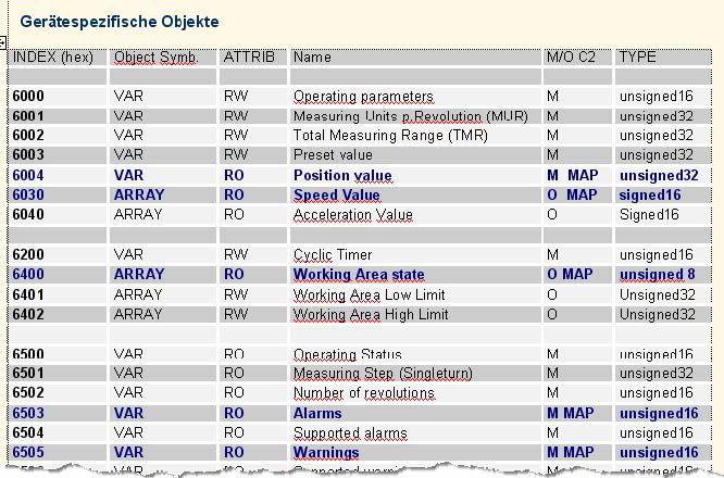
3116 CANopen Encoder Device Profile DS 406 V3..2 Device-specific Objects INDEX (hex) Object Symb. ATTRIB Name M/O C2 TYPE 6000 VAR RW Operating parameters M Unsigned16 6001 VAR RW Measuring Units p.Revolution (MUR) M Unsigned32 6002 VAR RW Total Measuring Range (TMR) M Unsigned32 6003 VAR RW Preset value M Unsigned32 6004 VAR RO Position value M MAP Unsigned32 6030 ARRAY RO Speed Value O MAP Signed16 6040 ARRAY RO Acceleration Value O Signed16 6200 VAR RW Cyclic Timer M Unsigned16 6400 ARRAY RO Working Area state O MAP Unsigned 8 6401 ARRAY RW Working Area Low Limit O Unsigned32 6402 ARRAY RW Working Area High Limit O Unsigned32 6500 VAR RO Operating Status M Unsigned16 6501 VAR RO Measuring Step (Singleturn) M Unsigned32 6502 VAR RO Number of revolutions M Unsigned16 6503 VAR RO Alarms M MAP Unsigned16 6504 VAR RO Supported alarms M Unsigned16 6505 VAR RO Warnings M MAP Unsigned16 6506 VAR RO Supported warnings M Unsigned16 6507 VAR RO Profile and SW version M Unsigned32 6508 VAR RO Operating time M Unsigned32 6509 VAR RO Offset value (calculated) M Signed32 650A VAR RO Module Identification M Signed32 650B VAR RO Serial Number M Unsigned32 VAR = Variable ARRAY = Variable Array RW = Read/Write RO = Read only const = Constants Name = Object Name M/O = Mandatory or Optional MAP = Object mappable 32 Turck Inc. | 3000 Campus Drive, Minneapolis, MN 55441 | T +1 800 544 7769 | F +1 763 553 0708 | www.turck.com
17 Objects in detail - Encoder Profile DS 306 V3..2
Object 6000h Operating Parameters
Bit 0: Code sequence:    0 = increasing when turning clockwise (cw)
                         1 = increasing when turning counter-clockwise (ccw)
                         Default: Bit = 0
Bit 2: Scaling Function: 0 = disable,
                         1 = enable; Standard: Bit = 1 (s. Object 6001,6002)
                         Default: Bit = 0
Bit14: Startup Mode:     0 = after Bootup Pre-Operational,
                         1 = after Bootup Operational mode
                         Default Bit = 0
Bit15: Event Mode:       0 = Position output acc. to TPDO 1800h,
                         1 = output on each change of position
                         Default Bit = 0

 Bit                    Function                                              Bit = 0              Bit =1                C1    C2
 0                      Code sequence                                         CW                   CCW                   m*    m*
 1                      Commissioning Diagnostic Control                      Disabled             Enabled               o     o
 2                      Enable scaling                                        Disabled             Enabled               o     m
 3                      Measuring direction                                   Forward              Reverse               o**   o**
 4..13                  Reserved for further use
 14                     Startup automatic in OP-Mode                          Disabled             Enabled               o     o
 15                     Event Mode Position                                   Disabled             Enabled               o     o

*m       = Function must be supported
o        = optional
orange   = defaults

Object 6001h: measuring steps per revolution (Resolution)
This parameter configures the desired resolution per revolution. The encoder itself then internally calculates the appropriate scale
factor. The calculated scaling factor MUR (by which the physical position value will be multiplied) is worked out according to the
following formula:

MUR = Measuring steps per revolution (6001h) / phys. resolution Singleturn (6501h)

Data content:
                                            Byte 0      Byte 1       Byte 2         Byte 3
                                            2 ...2
                                              7   0
                                                        2 ...2
                                                         15   8
                                                                     2 ...2
                                                                      23   16
                                                                                    231...224

Range of values:      1....maximum physical resolution (16384) 14-bit
Default setting:      16384(14-bit)

                                                             WARNING:
                   After changing the measuring step it is necessary to set the preset value also to zero /or a value.

                                                                                                                                   33
Object 6002h: Total number of measuring steps
This parameters configures the total number Singleturn measuring steps. A factor will be applied to the maximum physical resolu-
tion. The factor is always < 1 . After the stated number of measuring steps, the encoder will reset itself to zero.
Data content:
Byte 0 Byte 1 Byte 2 Byte 3
2 ...2
7 0
2 ...2
15 8
2 ...2
23 16
231...224
Range of values: 1....maximum physical resolution (16384) 14-bit
Default setting: 16384 (14-bit)
WARNING:
After changing the measuring step it is necessary to set the preset value also to zero /or a value.
Object 6003h: Preset Value
The position value of the encoder will be set to this preset value. This allows, for example, for the encoder’s zero position to be
compared with the machine’s zero position.
Data content:
Byte 0 Byte 1 Byte 2 Byte 3
2 ...2
7 0
2 ...2
15 8
2 ...2
23 16
231...224
Range of values: 1.... maximum physical resolution (16384) 14-bit
Default setting: 0
WARNING:
After transmitting the new preset value (object 6003h), it is necessary to achieve a store command at object 1010h because of
the new offset values otherwise the preset is only valid during the actual power cycle.
Object 6004h: Position Value
The encoder transmits the current position value ( adjusted possibly by the scaling factor)
Data content:
Byte 0 Byte 1 Byte 2 Byte 3
2 ...2
7 0
2 ...2
15 8
2 ...2
23 16
231...224
Range of values: 1.... maximum physical resolution (16384) 14-bit
Object is mappable
34 Turck Inc. | 3000 Campus Drive, Minneapolis, MN 55441 | T +1 800 544 7769 | F +1 763 553 0708 | www.turck.comObject 6030h: Speed Value
The encoder outputs the current calculated speed (possibly with scaling factor) as a signed 16-bit value. The speed value is in rpm
and the measuring time varied between 10ms and 100 ms.
Data content:
Byte 0 Byte 1
2 ...2
7 0
215...28
Range of values: 0....maximum speed 6500 RPM
Note:
With values greater than 6500 RPM a warning message will be sent and the Warning Bit “Overspeed Bit 0” in the Object Warnings
6505h will be set.
Object is mappable
Object 6200h: Cyclic Timer
Defines the cycle time, with which the current position will be output by means of PDO 1 (see Object 1800h). The timer-controlled
output becomes active, as soon as a cycle time >0 is entered.
Note:
This Object is only present for reasons of compatibility with earlier profile versions. Instead of this Object, please use the Event
Timer Sub index (05h) in the current Transmit PDO.
Data content:
Byte 0 Byte 1
2 ...2
7 0
215...28
Range of values: 0 ... FFFFh (65535) gives a cycle time in milliseconds
Standard value = 0h
Object 6500h: Display Operating Status
This Object displays the status of the programmed settings of Object 6000h.
Data content:
Byte 0 Byte 1
2 ...2
7 0
215...28
Data content: see Object 6000h
35Object 6503h: Alarms
In addition to the errors that are signaled via emergency messages, Object 6503h provides for further error messages. The
corresponding error bit is set to 1 for as long as the error condition applies.
Data content:
Byte 0 Byte 1
2 ...2
7 0
215...28
Bit No. Description Value = 0 Value = 1
Bit 0 Position error Position value valid Position error
Bit 1 Hardware check No error Error
Bit 2..15 Not used
If an error occurs, then in both cases an emergency message (ID=80h+node number) with the error code
1000h (Generic error) is sent.
Object is mappable
Object 6504h: Supported Alarms
This Object is used to display which alarm messages are supported by the encoder (see Object 6503h).
Data content:
Byte 0 Byte 1
2 ...2
7 0
215...28
Range of values: see Object 6503h
The alarm message is supported when the bit is set to 1
Example:
Bit 0 = 1 Position error display is supported
36 Turck Inc. | 3000 Campus Drive, Minneapolis, MN 55441 | T +1 800 544 7769 | F +1 763 553 0708 | www.turck.comObject 6505h: Warnings
Warning messages show that tolerances of internal encoder parameters have been exceeded. With a warning message – unlike
with an alarm message or emergency message – the measured value can still be valid. The corresponding warning bit will be set
to 1 for as long as the tolerance is exceeded or the warning applies.
Data content:
Byte 0 Byte 1
2 ...2
7 0
215...28
Bit No. Description Value = 0 Value = 1
Bit 0 Overspeed none exceeded
Bit 1..15 Not used
When Bit 0 is active then simultaneously an emergency message (ID=80h+node number) with the Error code 4200h (Device
specific) is sent.
Object is mappable
Object 6506h: Supported Warnings
This Object is used to display which warning messages are supported by the encoder (see Object 6505h).
Data content:
Byte 0 Byte 1
2 ...2
7 0
215...28
Range of values: see Object 6505h
The warning is supported when the bit is set to 1
37Object 6400h: Working Area State Register
This Object contains the current state of the encoder position with respect to the programmed limits. The flags are either set or
reset depending on the position of both limit values. The comparison with both limit values takes place in “real time” and can be
used for real-time positioning or for limit switching.
Work_area_state
Bit 7 Bit 6 Bit 5 Bit 4 Bit 3 Bit 2 Bit 1 Bit 0
smaller than larger than outside range1
LowLimit1 HighLimit1
Range of values 8-bit Data content see Bit 0...7
Note:
Both limit values Object 6401h and 6402h must be checked to ensure that the output signals are correctly activated!
Object is mappable
Object 6401h: Working Area Low Limit
Object 6402h: Working Area High Limit
These two parameters configure the working area. The state inside and outside this area can be signalled by means of Flag bytes
(Object 6400h Working Area State). These area markers can also be used as software limit switches.
Data content:
Byte 0 Byte 1 Byte 2 Byte 3
2 ...2
7 0
2 ...2
15 8
2 ...2
23 16
231...224
Range of values: 1....maximum physical resolution (268435456) 28-bit
Default setting: 16384 (14-bit) Working Area High Limit
0 Working Area Low Limit
Object 2100h: Baud rate
This Object is used to change the baud rate via software. If the value is set between 1..9 and the parameter saved, then on the next
Power ON or with a reset node, the device will boot up with the modified baud rate. After changing the baudrate it is necessary to
save the parameters with object 2105h permanently in the EEprom.
Data content:
Byte 0
27...20
Range of values 1 ...8 ( see Table CANopen Baudrate)
Default setting: 05h
38 Turck Inc. | 3000 Campus Drive, Minneapolis, MN 55441 | T +1 800 544 7769 | F +1 763 553 0708 | www.turck.comYou can also read


