SIMATIC NET S7-CPs for Industrial Ethernet
←
→
Page content transcription
If your browser does not render page correctly, please read the page content below
SIMATIC NET

S7-CPs for Industrial Ethernet

Manual Part B

 Gateway IWLAN/PB Link PN IO
 6GK1417-5AB00 / 6GK1417-5AB01               As of version 1 (firmware version V 1.1)

                                                                       Connection to PROFIBUS:
  LED indicators                                                       9-pin D -sub female connector

 Labeling strips / slot for
 C -PLUG

                                                               Antenna socket:
                                                               Connection for suitable IWLAN antenna

                              Power supply

Release 07/2008
C79000 - G8976 - C200 - 04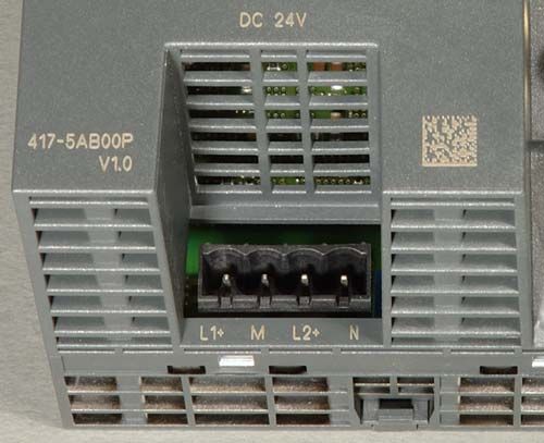
Notes on the product

Notes on the product

Product names:
            This description contains information on the product
            S   IWLAN/PB Link PN IO             Order no.: 6GK1417-5AB00
                                                Order no.: 6GK1417-5AB01 (US variant)

Product information accompanying the product

            Notice
            All the notes provided in the compact operating instructions supplied with the
            device described here are valid and must be observed.

General information about the documentation
            All the documents mentioned here can be found on the SIMATIC NET Industrial
            Wireless LAN CD supplied with the IWLAN/PB Link PN IO or are available via
            Internet.

Documentation about the IWLAN/PB Link PN IO
            S   ”S7 CPs for Industrial Ethernet Configuration and Commissioning” manual with
                the following components:
                - General Part A
                   Contains basic information about operating, configuring, and diagnosing CPs
                   and gateways for SIMATIC S7.
                - Device-specific Part BL2 ”IWLAN/PB Link PN IO Gateway”
                  (this documentation)
                   Contains information about installation, commissioning, and configuration.
            S   Operating Instructions (compact) - hard copy
                Contains safety instructions, certifications, and warnings.

Additional documentation about operating the IWLAN/PB Link PN IO
            S   Ooperating Instructions
                SCALANCE W788-xPRO/RR /
                SCALANCE W74x-1PRO/RR
            S   RCoax system manual

                                        Gateway IWLAN/PB Link PN IO for Industrial Ethernet / Manual Part B
B-2                                                                                       Release 07/2008
                                                                                 C79000-G8976-C200-04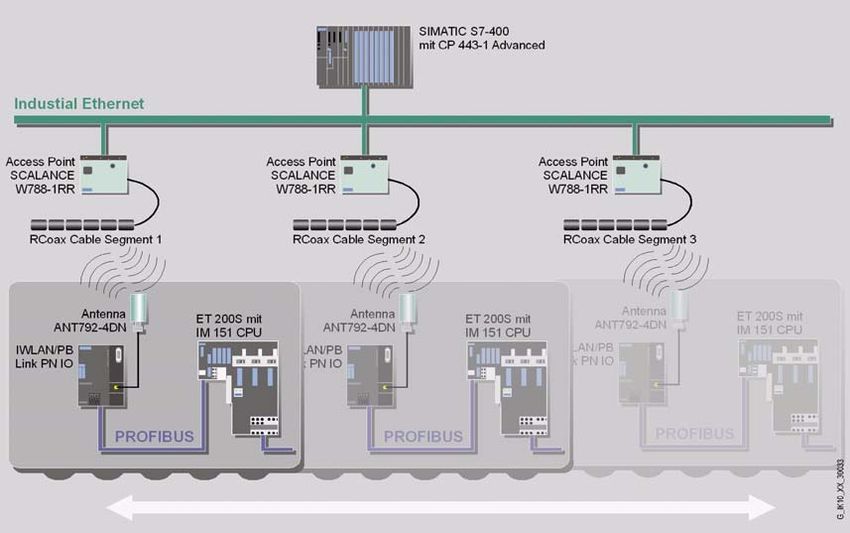
Contents

Contents

Contents - Part A
        S7-CPs - General information . . . . . . . . . . . . . . . . . . . . . . . .                                          see general part

                   Note
                   Please remember that Part A of the manual also belongs to the description of the
                   CP / Link. This contains - among other things - an explanation of the safety
                   instrucions provided, references, and further information about all S7-CPs /
                   IWLAN/IE/PB Link for Industrial Ethernet.
                   The following revision level of Part A belongs to Part B of the manual: as of
                   1/2005
                   You can download the current general Part A from the Internet:
                   http://support.automation.siemens.com/WW/news/en/8777865

Contents - Part BL2
        Notes on the product . . . . . . . . . . . . . . . . . . . . . . . . . . . . . . . . . . . . . . . . . . . . . . . . . . .                B-2
        General information about the documentation . . . . . . . . . . . . . . . . . . . . . . . . . . . .                                       B-2
        Contents . . . . . . . . . . . . . . . . . . . . . . . . . . . . . . . . . . . . . . . . . . . . . . . . . . . . . . . . . . . . . . .    B-3
1   Properties and Services . . . . . . . . . . . . . . . . . . . . . . . . . . . . . . . . . . . . . . . . . . . . . . . .                       B-5
2   Structure . . . . . . . . . . . . . . . . . . . . . . . . . . . . . . . . . . . . . . . . . . . . . . . . . . . . . . . . . . . . . .        B-11
3   Installation and Commissioning . . . . . . . . . . . . . . . . . . . . . . . . . . . . . . . . . . . . . . . . .                             B-12
        3.1             Installation and Parameter Assignment with the PRESET PLUG . . . .                                                       B -13
        3.2             Configuring the PRESET PLUG . . . . . . . . . . . . . . . . . . . . . . . . . . . . . . . .                              B -15
        3.3             Establishing the Connections . . . . . . . . . . . . . . . . . . . . . . . . . . . . . . . . . .                         B -17
        3.3.1           Important Notes . . . . . . . . . . . . . . . . . . . . . . . . . . . . . . . . . . . . . . . . . . . . . .              B -17
        3.3.2           PG/PC Connection . . . . . . . . . . . . . . . . . . . . . . . . . . . . . . . . . . . . . . . . . . .                   B -18
        3.3.3           Power Supply . . . . . . . . . . . . . . . . . . . . . . . . . . . . . . . . . . . . . . . . . . . . . . . .             B -19
        3.4             Installation and Parameter Assignment without the PRESET PLUG .                                                          B -20
        3.5             C-PLUG (Configuration Plug) . . . . . . . . . . . . . . . . . . . . . . . . . . . . . . . . . .                          B -22
4   Configuration with STEP 7 . . . . . . . . . . . . . . . . . . . . . . . . . . . . . . . . . . . . . . . . . . . . . .                        B-25
        4.1             Use as a PROFINET IO Device and as a Gateway . . . . . . . . . . . . . . .                                               B -26
        4.1.1           Configuring the Properties with STEP 7 . . . . . . . . . . . . . . . . . . . . . . . . .                                 B -26
        4.1.2           Update Time for the PROFINET IO System . . . . . . . . . . . . . . . . . . . . . .                                       B -28
        4.1.3           Assigning Device Names and Downloading the Configuration . . . . . .                                                     B -30
        4.2             Use As a Gateway Only . . . . . . . . . . . . . . . . . . . . . . . . . . . . . . . . . . . . . . .                      B -31

Gateway IWLAN/PB Link PN IO for Industrial Ethernet / Manual Part B
Release 07/2008                                                                                                                                  B-3
C79000-G8976-C200-04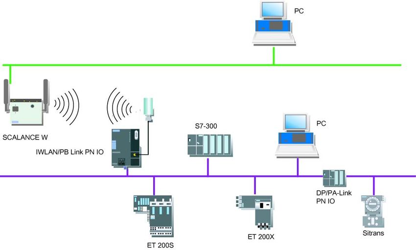
Contents

         4.2.1           Configuring the Properties with STEP 7 . . . . . . . . . . . . . . . . . . . . . . . . .                               B -31
         4.2.2           Assigning the IP Address and Loading the Configuration . . . . . . . . . . .                                           B -32
         4.3             Parameters in the Properties Dialog Box for IWLAN/PB Link PN IO .                                                      B -33
         4.3.1           Setting the Properties in the Basic Module . . . . . . . . . . . . . . . . . . . . . . .                               B -34
         4.3.2           Setting Properties in the IWLAN Interface Submodule . . . . . . . . . . . . .                                          B -35
         4.3.3           Setting the Properties in the PROFIBUS Submodule . . . . . . . . . . . . . .                                           B -36
5    Restoring the Standard Settings . . . . . . . . . . . . . . . . . . . . . . . . . . . . . . . . . . . . . . . .                            B-37
         5.1             WLAN Settings as Shipped (Default Status) . . . . . . . . . . . . . . . . . . . . . .                                  B -37
         5.2             Memory Reset or Resetting to Factory Settings . . . . . . . . . . . . . . . . . .                                      B -38
         5.2.1           Memory Reset . . . . . . . . . . . . . . . . . . . . . . . . . . . . . . . . . . . . . . . . . . . . . . .             B -38
         5.2.2           Resetting to the Factory Settings using NCM Diagnostics -
                         (WLAN parameters are retained) . . . . . . . . . . . . . . . . . . . . . . . . . . . . . . .                           B -39
         5.2.3           Resetting to Factory Settings with the RESET Button -
                         WLAN parameters are reset) . . . . . . . . . . . . . . . . . . . . . . . . . . . . . . . . . .                         B -39
6    LEDs . . . . . . . . . . . . . . . . . . . . . . . . . . . . . . . . . . . . . . . . . . . . . . . . . . . . . . . . . . . . . . . . . .   B-41
7    Performance Data . . . . . . . . . . . . . . . . . . . . . . . . . . . . . . . . . . . . . . . . . . . . . . . . . . . . . .               B-43
         7.1             Characteristic Data for Wireless Links . . . . . . . . . . . . . . . . . . . . . . . . . . .                           B -43
         7.2             S7 Communication Characteristics . . . . . . . . . . . . . . . . . . . . . . . . . . . . .                             B -43
         7.3             Features of Data Record Routing . . . . . . . . . . . . . . . . . . . . . . . . . . . . . . .                          B -43
         7.4             Total Number of Connections . . . . . . . . . . . . . . . . . . . . . . . . . . . . . . . . . .                        B -44
         7.5             Characteristic Data for PROFINET IO . . . . . . . . . . . . . . . . . . . . . . . . . . .                              B -44
8    Compatibility with Predecessor Products . . . . . . . . . . . . . . . . . . . . . . . . . . . . . . . .                                    B-45
         8.1             Use as a replacement: . . . . . . . . . . . . . . . . . . . . . . . . . . . . . . . . . . . . . . . .                  B -45
9    Further notes regarding operation . . . . . . . . . . . . . . . . . . . . . . . . . . . . . . . . . . . . . .                              B-47
         9.1             Changing interface parameters during download . . . . . . . . . . . . . . . . . .                                      B -47
         9.2             Time forwarding . . . . . . . . . . . . . . . . . . . . . . . . . . . . . . . . . . . . . . . . . . . . . .            B -47
         9.3             SNMP agent . . . . . . . . . . . . . . . . . . . . . . . . . . . . . . . . . . . . . . . . . . . . . . . . .           B -47
9    How to Load New Firmware . . . . . . . . . . . . . . . . . . . . . . . . . . . . . . . . . . . . . . . . . . . . .                         B-49
11    Technical data . . . . . . . . . . . . . . . . . . . . . . . . . . . . . . . . . . . . . . . . . . . . . . . . . . . . . . . .            B-50
         11.1            Technical Specifications of the Module . . . . . . . . . . . . . . . . . . . . . . . . . .                             B -50
         11.1.1          Standards and Approvals . . . . . . . . . . . . . . . . . . . . . . . . . . . . . . . . . . . . . .                    B -51
12     FCC Approval . . . . . . . . . . . . . . . . . . . . . . . . . . . . . . . . . . . . . . . . . . . . . . . . . . . . . . . .             B-52

                                                                   Gateway IWLAN/PB Link PN IO for Industrial Ethernet / Manual Part B
B-4                                                                                                                  Release 07/2008
                                                                                                            C79000-G8976-C200-04
1   Properties and Services

1      Properties and Services

Application
               The IWLAN/PB Link PN IO is a gateway that connects the Industrial Wireless LAN
               (control level) and PROFIBUS (cell/field level) networks to each other.

                           SCALANCE W78x

               The IWLAN/PB Link PN IO supports access to all PROFIBUS DP slaves on the
               subordinate PROFIBUS; DP slaves complying with PROFIBUS DP-V0 are
               supported and, as of firmware version V1.1.0, also DP slaves complying with the
               DP-V1 standard and Siemens DP slaves.
               The Industrial Wireless LAN (IWLAN) with RCoax and WLAN antenna for wireless
               or non-contact data transmission is ideal for a variety of mobile applications,
               including monorail conveyors and high-bay storage and retrieval systems.
               The IWLAN/PB Link PN IO can be operated in the following modes:
               S   Gateway as PROFINET IO proxy
               S   Gateway in standard operation

Gateway IWLAN/PB Link PN IO for Industrial Ethernet / Manual Part B
Release 07/2008                                                                              B-5
C79000-G8976-C200-04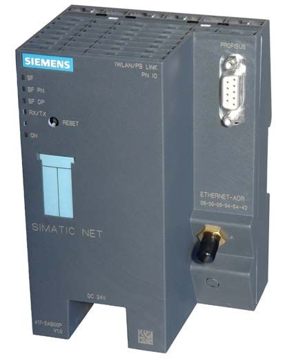
1   Properties and Services

Gateway as PROFINET IO proxy
                The IWLAN/PB Link PN IO is a key component of PROFINET IO. It is
                responsible for the connection between the PROFINET IO controllers on
                Industrial Ethernet and the PROFINET IO devices (DP slaves on PROFIBUS).
                From the point of view of the PROFINET IO controller on Industrial Ethernet,
                the process of accessing PROFINET IO devices that are connected to
                Industrial Ethernet via the Industrial Wireless LAN and IWLAN/PB Link PN IO
                and accessing PROFIBUS DP slaves that are connected to PROFIBUS DP is
                identical.
                The IWLAN/PB Link PN IO acts as a proxy for the DP slaves connected to
                PROFIBUS DP.

                                               SCALANCE W78x

Figure 1-1   Example of Using the IWLAN/PB Link PN IO PROFINET IO Proxy

                                        Gateway IWLAN/PB Link PN IO for Industrial Ethernet / Manual Part B
B-6                                                                                       Release 07/2008
                                                                                 C79000-G8976-C200-04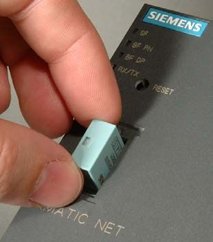
1   Properties and Services

Gateway in standard operation
               The following services are available in standard operation:
               S   PG/OP communication
                   PG/OP communication is used to download programs and configuration data,
                   run test and diagnostic functions, as well as operate and monitor the plant (HMI
                   systems).
               S   Assigning parameters to field devices (data record routing)
                   You can use the IWLAN/PB Link PN IO as a router for data records that are
                   addressed to field devices (DP slaves). In this way, devices that are not directly
                   connected to PROFIBUS and, therefore, cannot access the field devices (DP
                   slaves) directly, can transmit data records to the field devices via the
                   IWLAN/PB Link PN IO.
                   The SIMATIC PDM (Process Device Manager) is an example of a tool that
                   creates data records for assigning parameters to field devices.
               S   Gateway to a DP master system with constant bus cycle time
                   The IWLAN/PB Link PN IO acts as a gateway between the Industrial Wireless
                   LAN and the field devices on a DP master system. The IWLAN/PB Link PN IO
                   is used here as an active node along with a DP master on a PROFIBUS that
                   has been set to constant bus cycle time.
               S   Cross-subnet S7 connections for HMI operation
                   The IWLAN/PB Link PN IO forwards communication via S7 connections. This
                   service is used for HMI applications (PC stations), for example.

       SCALANCE W78x

Figure 1-2     Example of Using the IWLAN/PB Link PN IO in Standard Mode

Gateway IWLAN/PB Link PN IO for Industrial Ethernet / Manual Part B
Release 07/2008                                                                                  B-7
C79000-G8976-C200-04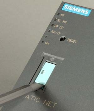
1   Properties and Services

Gateway in mobile applications
            The IWLAN/PB Link PN IO enables wireless communication with programmable
            controllers in mobile applications, such as automated guided vehicle systems,
            high-bay storage and retrieval systems, and monorail conveyors. Solutions
            involving power rail boosters for PROFIBUS via slip contacts can, therefore, be
            replaced with a non-contact, non-wearing data transmission technology.
            It can be connected via a WLAN antenna or an antenna for use with an RCoax
            cable (leak-mode conductor).

           Industrial Ethernet

Gateway in PROFINET IO applications with iPCF (industrial Point Coordination
Function)
            The IWLAN/PB Link PN IO supports iPCF mode.
            The use of iPCF is recommended particularly when a high throughput is required
            with large numbers of nodes or when very short handover times are necessary.
            The iPCF mechanism was further optimized for operation with PROFINET IO data
            traffic by handling PROFINET IO data traffic with high priority.

                                       Gateway IWLAN/PB Link PN IO for Industrial Ethernet / Manual Part B
B-8                                                                                      Release 07/2008
                                                                                C79000-G8976-C200-04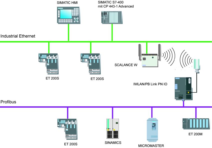
1   Properties and Services

               Notice
               For PROFINET IO communication, we recommend enabling the iPCF mode.
               Stable PNIO communication is only possible when it is guaranteed that a WLAN
               client is in a cell with more than 60% signal strength at all times. This can be
               checked by activating and deactivating the various segments.
               This does not mean that the client needs to change when there is a signal strength
               less than 60%. It is only necessary to make sure that a segment with adequate
               signal strength would be available.

               Note
               You will find a detailed description of the commands of the Command Line
               Interface (CLI) in the Operating Instructions SCALANCE W788-xPRO/RR /
               SCALANCE W74x-1PRO/RR. This manual (file name:
               BA_SCALANCE -W788-xPRO -RR-W74x -1PRO -RR_0.pdf) is available on the
               CD that accompanies the IWLAN/PB Link PN IO or on the Internet at:
               http://support.automation.siemens.com/WW/view/en/28529396

Gateway IWLAN/PB Link PN IO for Industrial Ethernet / Manual Part B
Release 07/2008                                                                              B-9
C79000-G8976-C200-04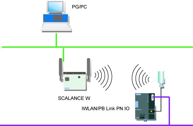
1   Properties and Services

Other properties and services
            S   Industrial wireless LAN
                IWLAN/PB Link PN IO provides a wireless interface (in compliance with IEEE
                802.11b/g/a/h.
            S   Forwarding time messages (configurable option)
                The IWLAN/PB Link PN IO can forward time messages received by a real-time
                transmitter as follows:
                - from Ethernet to PROFIBUS
                - From PROFIBUS to Ethernet
                If there is a time master on Industrial Ethernet, the IWLAN/PB Link PN IO then
                receives time messages for time stamping diagnostic buffer entries and process
                signals.
            S   Option: C-PLUG as exchangeable medium for the project engineering data
                The IWLAN/PB Link PN IO allows the configuration data to be saved to a
                removable memory medium (C-PLUG). In this way, a defective module can
                simply be replaced by plugging the C-PLUG into the new module.
            S   Option: PRESET-PLUG
                The PRESET PLUG is a simple device for assigning a defined default setting to
                an IWLAN/PB Link PN IO and SCALANCE W devices.
            S   WLAN Security Properties
                - Supported authentication standards:
                   WPA, WPA-PSK, IEEE 802.1x, WPA2, WPA2-PSK
                   Note: WPA2 (Wi-Fi Protected Access 2) includes the further development of
                   WPA that implements the functions of the security standard IEEE 802.11i.
                - Supported encryption methods:
                   WEP, AES, TKIP
            S   Downloading firmware
                IWLAN/PB Link PN IO supports updating of the firmware (FW) using the
                firmware loader supplied with STEP 7 / NCM S7.
                A firmware update can be downloaded at any time from the PC/PG via the
                Ethernet port.

Configuration
            You can configure the IWLAN/PB Link PN IO for all operating modes via Industrial
            Ethernet (recommended). If you use the device as a standard gateway, the
            configuration data can also be changed/supplied via PROFIBUS.

                                          Gateway IWLAN/PB Link PN IO for Industrial Ethernet / Manual Part B
B-10                                                                                        Release 07/2008
                                                                                   C79000-G8976-C200-04
2 Structure
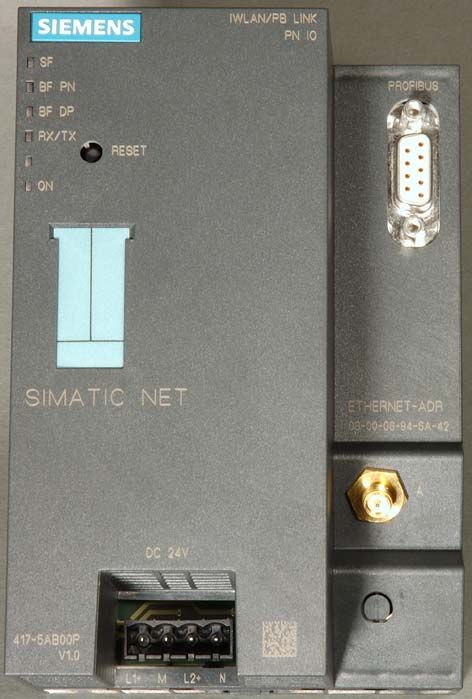
2 Structure
LED indicators Connection to PROFIBUS:
9-pin D -sub female connector
RESET button
Labeling strips / slot
for C-PLUG
Antenna socket:
Connection for suitable
IWLAN antenna
Power supply
Figure 2-1
The outer dimensions of the IWLAN/PB Link PN IO match the housing format of
the power rail booster. It is snapped onto a 35 mm DIN rail.
An antenna suitable for RCoax applications or an antenna for an IWLAN radio hop
is connected by means of a connecting plug. With degree of protection IP20, the
IWLAN/PB Link PN IO is suitable for installation in a cabinet.
The connections and display elements are all located on the front panel. The
optional C-PLUG is located under a cover, which is also on the front panel.
Other design features:
S No fan necessary
S R-SMA interface for connecting antennas;
S 9-pin D-sub female connector for connecting the IWLAN/PB Link PNIO to
PROFIBUS
S 4-pin terminal block for connecting a redundant external 24 V DC power
supply;
S LED indicators
Gateway IWLAN/PB Link PN IO for Industrial Ethernet / Manual Part B
Release 07/2008 B-11
C79000-G8976-C200-043 Installation and Commissioning
3 Installation and Commissioning
Use the overview below to find out which section is relevant to your application.
PRESET PLUG is available PRESET PLUG is not available
(recommended procedure)
Installation and Parameter Installation and Parameter
Assignment with PRESET PLUG Assignment without PRESET PLUG
-> see Section 3.1 -> see Section 3.4
The device has been commissioned on the WLAN side and can be
supplied with configuration data.
Subsequent procedure depending on application
Configuration with STEP 7 for use Configuration with STEP 7 for use
as a PROFINET IO device and as gateway only
gateway -> See Section 4.2
-> See Section 4.1
The device is ready
Gateway IWLAN/PB Link PN IO for Industrial Ethernet / Manual Part B
B-12 Release 07/2008
C79000-G8976-C200-043 Installation and Commissioning
3.1 Installation and Parameter Assignment with the PRESET
PLUG
The following section describes the recommended commissioning procedure with
the PRESET PLUG up to the parameter assignment stage. If a PRESET PLUG is
not used in your application, proceed as described in Section 3.4.
The project engineering that is subsequently required is described in Chapter 4
Please read the additional notes in this section. At this stage, installation and
configuration are carried out separately.
Follow the steps below:
Step Installation and Parameter Assignment with PRESET PLUG
1. Install the IWLAN/PB Link PN IO on a mounting rail.
2. Insert the PRESET PLUG into the C -PLUG slot.
The preset function of the PRESET PLUG only functions if the PRESET PLUG
was configured beforehand for the IWLAN/PB Link PN IO. If the PRESET
PLUG has not yet been configured, proceed as described in Section 3.2.
3. Connect the power supply to the IWLAN/PB Link PN IO
(read the notes in Section 3.3).
4. Switch the power supply on.
When the LEDs flash slowly, this indicates that the PRESET PLUG has been
recognized. The LEDs for the PRESET PLUG function are explained in the
device LED description; see Chapter 6
5. Press the reset button next to the C -PLUG slot.
The default settings for the PRESET PLUG are now copied to the device
where they are stored. When the settings have been successfully copied, the
LEDs stop flashing and switch to a steady -light signal after a few seconds.
6. Now switch off the power supply and remove the PRESET PLUG.
7. Connect the IWLAN/PB Link PN IO to PROFIBUS and, via the antenna, to
IWLAN.
8. Switch the power supply on.
The device now runs with the parameters transferred by the PRESET PLUG
and can be supplied with configuration data.
The device is now commissioned on the WLAN side and can be supplied with configuration
data.
9. Now continue with the configuration process depending on your application:
S Configuration with STEP 7 for use as a PROFINET IO device and gateway
-> see Section 4.2
S Configuration with STEP 7 for use as a gateway only -> see Section 4.1
Gateway IWLAN/PB Link PN IO for Industrial Ethernet / Manual Part B
Release 07/2008 B-13
C79000-G8976-C200-043 Installation and Commissioning
General notes
S IP parameters and device-specific parameters are not changed
Using the PRESET PLUG prevents duplicate IP addresses by ensuring that the
IP parameters are retained unchanged.
Other device-specific parameters also remain unchanged, including:
- System Contact
- System Name
- System Location
S The WLAN interface is deactivated.
The WLAN device interface is deactivated when the PRESET PLUG is
inserted. The device cannot be operated with the WLAN when the PRESET
PLUG is inserted.
Gateway IWLAN/PB Link PN IO for Industrial Ethernet / Manual Part B
B-14 Release 07/2008
C79000-G8976-C200-043 Installation and Commissioning
3.2 Configuring the PRESET PLUG
Overview
The PRESET PLUG is a simple device for assigning a defined default setting to an
IWLAN/PB Link PN IO and SCALANCE W devices.
The PRESET PLUG is first configured in a SCALANCE W788 with the required
WLAN parameters and then inserted in the C-PLUG slot on the target system for
commissioning purposes.
When several WLAN clients with the same parameters are used, the advantage of
this procedure is that you do not have to assign parameters to each individual
client manually.
If a PRESET PLUG is not used in your application, proceed as described in
Section 3.4.
Notice
The PRESET PLUG 6GK5798-8AB00 is only used for commissioning purposes.
The device cannot be operated with the WLAN when the PRESET PLUG is inser-
ted.
Configuring the PRESET PLUG
To configure a PRESET PLUG, you require a device of the type SCALANCE W7xx
with a firmware version V3.0 or higher.
You can use this procedure to configure a PRESET PLUG from scratch or to
change an existing configuration.
Follow the steps below:
Step Procedure
1. Insert a new PRESET PLUG or one that has already been configured into the
C -PLUG slot on the SCALANCE W7xx, which must be switched off.
2. Switch the device on.
3. Open the Web interface for the SCALANCE W7xx.
The Web interface displays the current settings for the PRESET PLUG
(provided a configuration already exists).
Gateway IWLAN/PB Link PN IO for Industrial Ethernet / Manual Part B
Release 07/2008 B-15
C79000-G8976-C200-043 Installation and Commissioning
Step Procedure
4. Set all the parameters as required for making the default settings for the target
devices:
S This involves specifying whether the target device is to function as an AP or
client. For the IWLAN/PB Link PN IO, choose ”Client”.
S To ensure that the IWLAN/PB Link PN IO can later establish a connection
with the AP correctly, adapt the following parameter settings to suit your
specific application:
- System / Country Code
- SSID
- WLAN Mode
- Security
- iPCF Mode (if necessary)
- Other settings may also be required for your application (e.g.
background scan channels).
5. When you have set all the parameters, open the System " C-PLUG menu and
select the ”Create PRESET PLUG” function.
6. Choose the target device type for which this PRESET PLUG is designed (in
this case: IWLAN/PB Link PN IO).
7. To complete the configuration, select ”Modify”.
The PRESET PLUG has now been configured.
8. Switch the SCALANCE W7xx off and remove the PRESET PLUG.
Note
The PRESET PLUG you have just configured only functions with the device type
you selected.
Gateway IWLAN/PB Link PN IO for Industrial Ethernet / Manual Part B
B-16 Release 07/2008
C79000-G8976-C200-043 Installation and Commissioning
3.3 Establishing the Connections
3.3.1 Important Notes
Notice
Important notes on installation and operation:
S The module must be installed so that its upper and lower ventilation slits are
not covered, allowing adequate ventilation.
Note
The PROFIBUS can be connected while the power supply is on.
Notice
The requirements of EN61000-4-5, surge immunity test on power supply lines,
are met only when using a Blitzductor VT AD 24V type no. 918 402 .
Manufacturer:
DEHN+SÖHNE GmbH+Co.KG Hans Dehn Str.1 Postfach 1640 D-92306
Neumarkt, Germany
Warning
! The IWLAN/PB Link PN IO product must be installed in an enclosure or
switchgear cabinet.
Where ATEX 100a (EN 50021) applies, this enclosure must meet at least IP54 in
compliance with EN 60529.
WARNING
THE DEVICE MAY ONLY BE CONNECTED TO THE POWER SUPPLY OR
DISCONNECTED FROM IT WHEN THE RISK OF EXPLOSION CAN BE
EXCLUDED WITH CERTAINTY.
Ground/chassis ground concept
The device is grounded over the mounting rail.
Gateway IWLAN/PB Link PN IO for Industrial Ethernet / Manual Part B
Release 07/2008 B-17
C79000-G8976-C200-043 Installation and Commissioning
Module accessories
The accessories (including the power supply) required for connecting the
IWLAN/PB Link PN IO to an Industrial Wireless LAN and PROFIBUS must be
ordered separately.
The optional C-PLUG can also be ordered separately.
For more detailed information and ordering data, refer to the Catalog IK PI.
3.3.2 PG/PC Connection
You can connect the PG when configuring the CP as follows:
S Via Industrial Ethernet and WLAN interface (recommended)
S Via PROFIBUS (for standard operation only)
Industrial Ethernet and WLAN interface (recommended)
Commissioning the device for the WLAN is described in detail in this chapter (3).
When configuring on the PG, a distinction must be made between the following
modes:
S PROFINET IO use case
In this use case, the IWLAN/PB Link PN IO obtains its project engineering data
from the controller. This means:
- Controller and Link must be connected over the WLAN;
- The Link must already have been assigned a device name with STEP 7 so
that the project engineering data can be downloaded.
Read the detailed description of project engineering in Section 4.1.
S Standalone Mode
In this use case, the IWLAN/PB Link PN IO is configured and downloaded as
an S7-300 station. This can take place as soon as you have assigned an
Ethernet address to the device with STEP 7. Read the detailed description of
project engineering in Section 4.2.
PROFIBUS (for standard operation only)
The IWLAN/PB Link PN IO can be reached over the PROFIBUS interface. You
must, however, first assign a PROFIBUS address in the project engineering.
Gateway IWLAN/PB Link PN IO for Industrial Ethernet / Manual Part B
B-18 Release 07/2008
C79000-G8976-C200-043 Installation and Commissioning
3.3.3 Power Supply
Warning
! The IWLAN/PB Link PN IO is designed for operation with safety extra-low voltage
(SELV). This means that only safety extra-low voltages (SELV) complying with
IEC950/EN60950/ VDE0805 may be connected to the power supply terminals.
The power supply unit to supply the IWLAN/PB Link PN IO must comply with NEC
Class 2 (voltage range 20.4 - 28.8 V, current requirement 300 mA).
The device must only be supplied by a power supply unit that complies with the
requirements of class 2 for power supply units of the ”National Electrical Code,
Table 11 (b)”. If the power supply is installed redundantly (two separate power
supplies), the total power of both power supplies together must meet these
requirements.
Exceptions:
S Supply by a SELV power source (complying with IEC 60950) or PELV power
source (complying with VDE 0100-410) without restricted power is also
permitted as long as suitable fire prevention measures are taken by means of:
- installation in cabinet or suitable enclosure
- installation in suitably equipped, closed room
The power supply is connected over a 4-pin plug-in terminal block. The power
supply can be connected redundantly. The two inputs are isolated. There is no load
sharing. When the supply is redundant, the power source with the higher output
voltage supplies the IWLAN/PB Link PN IO alone. The power supply is connected
to the housing over a high resistance to allow ungrounded installation.
L1+: +24 V DC
M: 24 V DC chassis
L2+: +24 V DC
M: 24 V DC chassis
Figure 3-1 Power Supply
Gateway IWLAN/PB Link PN IO for Industrial Ethernet / Manual Part B
Release 07/2008 B-19
C79000-G8976-C200-043 Installation and Commissioning
3.4 Installation and Parameter Assignment without the
PRESET PLUG
Overview
The PRESET PLUG is a simple device for assigning a defined default setting to an
IWLAN/PB Link PN IO and SCALANCE W devices.
If a PRESET PLUG is not used in your application, proceed as described below to
assign parameters for the IWLAN/PB Link PN IO.
Before carrying out the procedure described below, make sure that the device has
the default settings as shipped. If this is not the case, use the RESET button to
restore the factory settings (see Section 5.2.3)
Configuration
For the procedure described here, you need the following device configuration with
an AP with parameter settings for the configuration (configuration AP):
Configuration AP with SSID
“WLAN_CONFIG_AP”
Follow the steps below:
Step Procedure
1. Install the IWLAN/PB Link PN IO on a mounting rail.
2. Connect the device to IWLAN via the antenna.
3. If necessary, adapt the AP settings to the default settings for the
IWLAN/PB Link PN IO (see Section 5.1), so that it can be used as a
configuration AP.
Gateway IWLAN/PB Link PN IO for Industrial Ethernet / Manual Part B
B-20 Release 07/2008
C79000-G8976-C200-043 Installation and Commissioning
Step Procedure
4. Switch the power supply on.
The device can now be accessed via its MAC address in the WLAN.
5. Use the PST (Primary Setup Tool) to assign the IP address and PROFIBUS
parameters to the IWLAN/PB Link PN IO.
Note: The PST (Primary Setup Tool) is on the CD supplied with the product and
can be found in the following directory:
6. Log on to the IWLAN/PB Link PN IO via Telnet.
To do so, open the MS -DOS input prompt and enter the following
command:telnet
Use the following default values to log in:
S Login: admin
S Password: admin
7. Set the parameters for the IWLAN/PB Link PN IO over the Command Line
Interface (CLI) so that the device can be commissioned in the operational
environment in which the configuration is also loaded.
If necessary, adapt the Country Code in the first step and then make any
further settings you require.
If you modify parameters, you will be prompted to restart. You should, however,
only restart when you have made all relevant settings.
The device is now commissioned on the WLAN side and can be supplied with configuration
data.
8. After completing the settings, commission the IWLAN/PB Link PN IO in its
operative environment in the WLAN.
9. Now continue with the configuration process depending on your application:
S Configuration with STEP 7 for use as a PROFINET IO device and gateway
-> see Section 4.2
S Configuration with STEP 7 for use as a gateway -> see Section 4.1
Note
You will find a detailed description of the commands of the Command Line
Interface (CLI) in the Operating Instructions SCALANCE W788-xPRO/RR /
SCALANCE W74x-1PRO/RR. This manual (file name:
BA_SCALANCE -W788-xPRO -RR-W74x -1PRO -RR_0.pdf) is available on the
CD that accompanies the IWLAN/PB Link PN IO or on the Internet at:
http://support.automation.siemens.com/WW/view/en/28529396
Gateway IWLAN/PB Link PN IO for Industrial Ethernet / Manual Part B
Release 07/2008 B-21
C79000-G8976-C200-043 Installation and Commissioning
3.5 C-PLUG (Configuration Plug)
C-PLUG removable memory medium as an alternative to flash memory
The IWLAN/PB Link PN IO has an internal flash memory for storing the project
engineering data. As an option, the device can be operated with a C-PLUG
(configuration plug) removable memory medium.
The IWLAN/PB Link PN IO can be operated with or without a C-PLUG. The
existing flash memory is then only used when no C-PLUG is inserted.
If a C-PLUG is inserted, the project engineering data is always stored on it. This
simplifies replacement of modules. By simply exchanging the C-PLUG, all the data
can be transferred to the replacement module.
Response to an unknown or invalid C - PLUG
If a C-PLUG is inserted that does not have the correct format or valid data for the
IWLAN/PB Link PN IO, the IWLAN/PB Link PN IO will not start up. Device status:
System fault LED lit.
To ensure that you can access the IWLAN/PB Link PN IO via the WLAN interface
in this status, the WLAN parameters stored in the internal flash memory are used.
If you know this parameter, please format the C-PLUG with NCM diagnostics or
replace the C-PLUG with a C-PLUG with valid data.
If, however, you do not know this parameter and cannot establish a connection in
the WLAN, use the RESET button to run a ”reset to factory settings” with the
C-PLUG inserted (see Section 5.2); you then operate with the default WLAN
parameters.
Notice
The C-PLUG may only be inserted or removed when the power is turned off!
Gateway IWLAN/PB Link PN IO for Industrial Ethernet / Manual Part B
B-22 Release 07/2008
C79000-G8976-C200-043 Installation and Commissioning
Figure 3-2 Fitting a C-PLUG in the IWLAN/PB Link PN IO and Removing a C-PLUG from the
IWLAN/PB Link PN IO using a Screwdriver
Table 3-1 Working with and without a C-PLUG
Progress / status Behavior during data Result after startup
transmission
Settings as shipped (after parameter assignment with PRESET PLUG or over Telnet/CLI)
- Operation without C -PLUG
S C -PLUG not inserted. The configuration data is transferred The IWLAN/PB Link PN IO uses the
from the STEP 7 project. The configuration data transferred to the
following differentiation is made internal flash memory. 1)
here:
S Use as Gateway only: Project
engineering data transferred by
the download function of
STEP 7.
S Use as PROFINET IO device:
Project engineering data
transferred from PROFINET IO
controller.
C -PLUG inserted in the module with settings as shipped (after parameter assignment with the PRESET
PLUG or over Telnet/CLI)
S Empty C -PLUG is The configuration data is transferred The IWLAN/PB Link PN IO uses the
inserted. from the STEP 7 project. The configuration data transferred
following differentiation is made automatically from the internal flash
here: memory to the C -PLUG. 1)
S Use as PROFINET IO device:
Project engineering data
transferred from PROFINET IO
controller.
S Use as Gateway only: Project
engineering data transferred by
the download function of
STEP 7.
Gateway IWLAN/PB Link PN IO for Industrial Ethernet / Manual Part B
Release 07/2008 B-23
C79000-G8976-C200-043 Installation and Commissioning
Table 3-1 Working with and without a C-PLUG, continued
Progress / status Behavior during data Result after startup
transmission
S C -PLUG with Result after startup: The IWLAN/PB Link PN IO uses the
configuration data is The IWLAN/PB Link PN IO starts up configuration data on the C -PLUG.
inserted. with the project engineering data 1)
Requirement: Project stored on the C-PLUG.
engineering data must
be valid for the
IWLAN/PB Link PN IO 2)
In its configured state, the module is already equipped with the C -PLUG.
S Empty C -PLUG is When the IWLAN/PB Link PN IO is The IWLAN/PB Link PN IO uses the
inserted. started, the configuration data is configuration data transferred from
loaded from the internal flash the flash memory to the C -PLUG. 1)
memory to the C -PLUG.
The configuration data is deleted
from the internal flash memory.
S C -PLUG with the Provided that the C -PLUG for the Result:
configuration data is IWLAN/PB Link PN IO contains The IWLAN/PB Link PN IO starts up
inserted valid configuration data, this data is with the project engineering data
Requirement: Project used. The data in the internal flash stored on the C-PLUG. 1)
engineering data must memory is ignored.
be valid for the During the next startup, the internal
IWLAN/PB Link PN IO 2) flash memory is reset.
The internal WLAN parameters,
however, are not deleted.
1) Note on use as a PROFINET IO device: Only the device name and the WLAN parameters are stored
retentively on the C-PLUG; project engineering data is transferred by the PROFINET IO controller during
each startup and stored in volatile memory.
2) Note: If the C-PLUG has no valid project engineering data for the IWLAN/PB Link PN IO, the device will
not start up! In this case, use the NCM diagnostics to clarify the situation and, if necessary, format the
C -PLUG.
Gateway IWLAN/PB Link PN IO for Industrial Ethernet / Manual Part B
B-24 Release 07/2008
C79000-G8976-C200-044 Configuration with STEP 7
4 Configuration with STEP 7
To connect (initial addressing) and configure the IWLAN/PB Link PN IO, you need
the STEP 7/ NCM S7 configuration software (as of version V5.3 SP2 Hotfix 1.
Notice
If the hardware catalog of HW Config in your STEP 7 installation does not contain
the IWLAN/PB Link PN IO component, you have to also install the hardware up-
date in STEP 7 / HW Config.
The hardware update is on the CD supplied with the product and can be found in
the directory: software/HSP_1009
In STEP 7 / HW Config, choose:
Options " Install Hardware Updates...
For information on how to continue, see the online help in STEP 7.
After installation and parameter assignment, the device can be configured and the
configuration data downloaded in two different ways depending on the application:
Initial situation:
The device is commissioned at the WLAN end (see Section 3) and
can now be supplied with configuration data.
Subsequent procedure depending on application
Configuration with STEP 7 for use Configuration with STEP 7 for use
as a PROFINET IO device and as gateway only
gateway -> See Section 4.2
-> See Section 4.1
The device is ready
Gateway IWLAN/PB Link PN IO for Industrial Ethernet / Manual Part B
Release 07/2008 B-25
C79000-G8976-C200-044 Configuration with STEP 7
4.1 Use as a PROFINET IO Device and as a Gateway
For this application, configure the IWLAN/PB Link PN IO as a PROFINET IO
device with STEP 7/HW Config and assign a DP master system to the
IWLAN/PB Link PN IO.
Load the configuration data to the PROFINET IO controller, which then
automatically loads it to the IWLAN/PB Link PN IO.
Notice
You must always restore the factory settings when you switch the configured IW-
LAN/PB Link PN IO operating mode. The device can only be operated as a PRO-
FINET IO device or as a gateway.
4.1.1 Configuring the Properties with STEP 7
To assign address information and further parameters to the
IWLAN/PB Link PN IO, you have to generate a loadable database (configuration)
in STEP 7.
Follow the steps below
Step Configuring the IWLAN/PB Link PN IO as a PROFINET IO device with
STEP 7/HW Config
1. Use an existing STEP 7 project in which you have already created a PROFINET IO
controller (e.g. an S7-400 station with a CP 443-1 Advanced).
2. Open HW Config by double-clicking the station you created .
3. Take the device type gateway IWLAN/PB Link PN IO from the hardware catalog under
PROFINET IO and add this as an IO device on the PN IO system of the IO controller.
An IP address for the PROFINET IO system interface is determined automatically here.
STEP 7 also assigns a device number to the IWLAN/PB Link PN IO. It chooses the highest
free device number in the current PROFINET IO system.
Step Connecting the PROFIBUS subnet in the STEP 7 project
4. Once you have transferred the IWLAN/PB Link PN IO from the hardware catalog, you are
prompted to network the IWLAN/PB Link PN IO to the PROFIBUS interface.
If you have not yet created the required subnets, you can do this now by selecting the
relevant entry. This creates a DP master system.
Results:
In HWConfig, the IWLAN/PB Link PN IO is created as a PROFINET IO device with a DP master system.
Gateway IWLAN/PB Link PN IO for Industrial Ethernet / Manual Part B
B-26 Release 07/2008
C79000-G8976-C200-044 Configuration with STEP 7
Step Connecting the PROFIBUS subnet in the STEP 7 project
5. Set any other required properties of the IWLAN/PB Link PN IO (see also Section 4.3).
6. Configure the DP master system and its DP slaves.
Note
For the IWLAN/PB Link PN IO, the DP master system is assigned to the
PROFIBUS submodule. If you want to create a new DP master system, therefore,
you first have to choose the PROFIBUS submodule.
Gateway IWLAN/PB Link PN IO for Industrial Ethernet / Manual Part B
Release 07/2008 B-27
C79000-G8976-C200-044 Configuration with STEP 7
4.1.2 Update Time for the PROFINET IO System
You can display and set the parameters described below in the properties dialog
box for the PROFINET IO system in HW Config.
Setting the update time
Update times can only be set in certain intervals. STEP 7 determines the relevant
values on the basis of the properties of the IO devices involved.
If you change the basic hardware configuration, for example, add new IO devices,
the update time can change. The next time you open the dialog, a message
informs you that the update time has changed.
The default value for the update time is calculated automatically depending on the
maximum number of links on an IWLAN segment (or AP).
Notice
Note that the update time you choose for the SCALANCE W788-RR must be iden-
tical to the setting described here for the IWLAN/PB Link PN IO in the STEP 7
configuration.
Set the update time over the CLI in the following menu: “ifeature " ipcf " PN IO
Update Time
Selection of channels to be scanned
The minimum selectable update time is decided by the number of WLAN clients on
an access point in the configuration in STEP 7.
To keep the proportion of cycle time required for scanning channels to a minimum
when roaming, we recommend that you use the “Background scan channels”
setting. This restricts the number of channels on which the IWLAN/PB Link PN IO
scans for a channel.
To use this, select the following settings in the “Interfaces " wlan1 " Advanced”
menu:
S Background scan channel select -> activates the background scan
S Background scan channels -> selection of channels to be scanned
This optimizes the roaming characteristics in terms of time.
Gateway IWLAN/PB Link PN IO for Industrial Ethernet / Manual Part B
B-28 Release 07/2008
C79000-G8976-C200-044 Configuration with STEP 7
Optimizing the update time
You can optimize the update time by specifying the maximum number of links in
your system on the ”IWLAN Parameters” tab.
Notice
If the update time you choose is too short or if the IWLAN segment has more links
than you specified on the ”IWLAN Parameters” tab, this may cause the connection
to be interrupted. For this reason, you are advised to retain the default settings.
When optimizing the update time, you must take into account the following points
to ensure stable communication:
S Case a: your system is operated in a single wireless segment; in other words,
the clients (IWLAN/PB links, SCALANCE W74x) do not need to support
roaming to another wireless segment.
In this case, update times of >=8 ms are supported.
Optimum wireless conditions without roaming: update times of 4 ms are only
possible under optimum wireless conditions and when the cell has just one
client.
S Case b: your system is operated with two wireless segments on two different
channels.
In this case, update times of >=16 ms are also supported.
S Case c: your system is operated with more than one wireless segment and
more than two channels. The clients also switch between the segments (roam).
In this case, the PN IO update time should be higher than 16 ms.
Notice
You are strongly advised to check the local radio conditions before commissioning.
Note
You will find a detailed description of the commands of the Command Line
Interface (CLI) in the Operating Instructions SCALANCE W788-xPRO/RR /
SCALANCE W74x-1PRO/RR. This manual (file name:
BA_SCALANCE -W788-xPRO -RR-W74x -1PRO -RR_0.pdf) is available on the
CD that accompanies the IWLAN/PB Link PN IO or on the Internet at:
http://support.automation.siemens.com/WW/view/en/28529396
Gateway IWLAN/PB Link PN IO for Industrial Ethernet / Manual Part B
Release 07/2008 B-29
C79000-G8976-C200-044 Configuration with STEP 7
4.1.3 Assigning Device Names and Downloading the Configuration
The IWLAN/PB Link PN IO is supplied with a fixed MAC address. Without further
configuration, the device can only be accessed over the WLAN port using this
MAC address.
An IP address is automatically assigned during configuration. Later when the
PROFINET IO controller is started up, this IP address is transferred to the
IWLAN/PB Link PN IO (IO device).
To ensure that the IO controller can identify the IO device during this procedure,
you first have to assign a device name to the IWLAN/PB Link PN IO as you do to
every other IO device. You only have to assign the name once.
Follow the steps below
Step Procedure
1. Assign a device name to the IWLAN/PB Link PN IO (you only have to do this once).
You can do this in the SIMATIC Manager or in HW Config with the menu command
PLC " Ethernet " Assign device name...
(More detailed information on this procedure is available in the STEP 7 online help.)
2. Load the configuration for the associated PROFINET IO controller.
The IO controller receives the configuration data from the IWLAN/PB Link PN IO. When the
IO controller is started up, the IWLAN/PB Link PN IO and all the other PROFINET IO
devices are configured automatically.
Note
The configuration data loaded by the PROFINET IO controller is not stored
retentively by the IWLAN/PB Link PN IO. When you switch the device off and then
on again, all the configuration data except for the device name is deleted. During
startup, the configuration data is reloaded by the PROFINET IO controller.
Gateway IWLAN/PB Link PN IO for Industrial Ethernet / Manual Part B
B-30 Release 07/2008
C79000-G8976-C200-044 Configuration with STEP 7
4.2 Use As a Gateway Only
For this application, configure the IWLAN/PB Link PN IO as an S7-300 station with
STEP 7/HW Config and load the configuration data to the IWLAN/PB Link PN IO.
Notice
You must always restore the factory settings via NCM diagnosis (see Section
5.2.2) when you switch the configured IWLAN/PB Link PN IO operating mode. The
device can only be operated as a PROFINET IO device or as a gateway.
4.2.1 Configuring the Properties with STEP 7
Follow the steps below
Step Configuring the IWLAN/PB Link PN IO as an S7-300 station with STEP 7/HW Config
1. Use an existing STEP 7 project or create a new one.
2. Create a station of type SIMATIC 300.
3. Open HWConfig by double-clicking the station you created.
4. From the hardware catalog under SIMATIC 300 / gateway, choose the device type
IWLAN/PB Link PN IO.
Gateway IWLAN/PB Link PN IO for Industrial Ethernet / Manual Part B
Release 07/2008 B-31
C79000-G8976-C200-044 Configuration with STEP 7
Step Connect the IWLAN/PB Link PN IO to the Ethernet and PROFIBUS subnet in the
STEP 7 project
5. Once you have copied the IWLAN/PB Link PN IO from the hardware catalog, you are
prompted to network the IWLAN/PB Link PN IO on the Ethernet interface and then on the
PROFIBUS interface.
If you have not yet created the required subnets, you can do this now by selecting the
relevant entry.
Result:
You have created the IWLAN/PB Link PN IO component with a basic module and the
Ethernet and PROFIBUS submodules in the S7-300 station in HW Config.
6. Set any other properties of the IWLAN/PB Link PN IO. For more information about this, see
Sections 4.3.1 to 4.3.3.
4.2.2 Assigning the IP Address and Loading the Configuration
The IWLAN/PB Link PN IO is supplied with a fixed MAC address. Without further
configuration, the device can only be accessed via the WLAN connection using this
MAC address.
Step Commissioning the IWLAN/PB Link PN IO
7. Assign an IP address to the IWLAN/PB Link PN IO provided you have not already done this
in the SIMATIC Manager independently of the configuration steps described here.
To do so, choose the following menu command in HW Config
PLC " Ethernet " Assign Ethernet Address...
8. Load the database (configuration) from STEP 7 to the IWLAN/PB Link PN IO.
The initial load process must be carried out from the Industrial Wireless LAN via the TCP/IP
interface. Subsequent load processes can be carried out from PROFIBUS or the Industrial
Wireless LAN via the TCP/IP interface depending on the PG connection.
Notice
Note that the IWLAN/PB Link PN IO is a special configuration component that
already contains all the required station components. For this reason, you cannot
place any other component (e.g. rack or modules) next to the IWLAN/PB
Link PN IO.
Gateway IWLAN/PB Link PN IO for Industrial Ethernet / Manual Part B
B-32 Release 07/2008
C79000-G8976-C200-044 Configuration with STEP 7
4.3 Parameters in the Properties Dialog Box for IWLAN/PB Link PN IO
You can set the other IWLAN/PB Link PN IO properties in HWConfig or via the
component view in NetPro (with gateway operation only).
4.3.1 Setting the Properties in the Basic Module
Opening the properties dialog
Selection option (example used here:
in NetPro for operation as a
gateway):
After selecting the basic module and
opening the object properties, you
can make the following settings:
S “General” tab
Here, you can enter general information such as a technological name to be
used for component management in the STEP 7 project.
S “Options” tab
- Time-of-day synchronization
Here, you can set whether the IWLAN/PB Link PN IO is to forward time
messages from a real-time transmitter. Selectable directions: from
PROFIBUS to Ethernet or from Ethernet to PROFIBUS.
- Assigning parameters to field devices (data record routing)
Here, you can decide whether or not the device is to support data record
routing for assigning parameters to field devices. As default, the option is
activated.
S “Device number” tab (only with operation as PROFINET IO device)
The DP slaves are addressed as an IO device from the PROFINET IO
controller using the PROFINET IO device number. ”Device number” tab You
can display the device numbers of the DP slaves, which are assigned
automatically. You can change the device numbers.
Gateway IWLAN/PB Link PN IO for Industrial Ethernet / Manual Part B
Release 07/2008 B-33
C79000-G8976-C200-044 Configuration with STEP 7
S “Diagnostics” tab
Here, you can call up the NCM diagnosis directly when the
IWLAN/PB Link PN IO is online.
Note
You will find more detailed information on this procedure in the STEP 7 online
help.
4.3.2 Setting Properties in the IWLAN Interface Submodule
In NetPro, the S7-300 station you have
configured is displayed as shown here:
Selection option (example used here:
in NetPro for operation as a
gateway):
You can make the settings described
here by selecting the IWLAN
interface submodule and opening the
object properties:
In HW Config, the S7-300 station you
have configured is displayed as shown
below:
Gateway IWLAN/PB Link PN IO for Industrial Ethernet / Manual Part B
B-34 Release 07/2008
C79000-G8976-C200-044 Configuration with STEP 7
These properties can be configured:
S “General” tab
Here, you can enter general information to be used for component management
in the STEP 7 project. You can also set parameters for the interface to Ind.
Ethernet.
Note
You will find more detailed information on this procedure in the STEP 7 online
help.
Gateway IWLAN/PB Link PN IO for Industrial Ethernet / Manual Part B
Release 07/2008 B-35
C79000-G8976-C200-044 Configuration with STEP 7
4.3.3 Setting the Properties in the PROFIBUS Submodule
Selection option (example used here:
in NetPro for operation as a
gateway):
After selecting the PROFIBUS/DP
submodule and opening the object
properties, you can make the
following settings:
S “General” tab
Here, you can set the parameters for the interface to PROFIBUS; in other
words, assign the network and the PROFIBUS address.
You can also enter general information to be used for component management
in the STEP 7 project.
S “Addresses” tab
The address parameter displayed here for diagnostic purposes is not relevant
for the IWLAN/PB Link PN IO.
S ”Operating Mode” tab
Here, you can (de)select the PROFIBUS DP operating mode.
In the “No DP” mode, the IWLAN/PB Link PN IO behaves like a PG/PC. By
configuring the IWLAN/PB-Link in the “DP Master” mode with an attached DP
master system, you allow direct data access between connected DP slaves.
Gateway IWLAN/PB Link PN IO for Industrial Ethernet / Manual Part B
B-36 Release 07/2008
C79000-G8976-C200-045 Restoring the Standard Settings
5 Restoring the Standard Settings
5.1 WLAN Settings as Shipped (Default Status)
When shipped, the IWLAN/PB Link PN IO is configured so that it uses an AP
(access point) to connect to the SSID ”WLAN_CONFIG_AP” after startup.
Note: The configuration AP must be operated as follows in 802.11g mode:
S Country code: Germany
S As Open System (Security)
S Without iPCF 1)
Note
You will find a detailed description of the commands of the Command Line
Interface (CLI) in the Operating Instructions SCALANCE W788-xPRO/RR /
SCALANCE W74x-1PRO/RR. This manual (file name:
BA_SCALANCE -W788-xPRO -RR-W74x -1PRO -RR_0.pdf) is available on the
CD that accompanies the IWLAN/PB Link PN IO or on the Internet at:
http://support.automation.siemens.com/WW/view/en/28529396
Parameter assignment without the PRESET PLUG using the Primary Setup Tool
and CLI
The behavior in the default status as shipped allows an IP address to be assigned
to the device by means of STEP 7 or the PST (Primary Setup Tool) after which it
can be assigned parameters by means of remote configuration with Telnet and the
Command Line Interface (CLI).
Note
The PST (Primary Setup Tool) is on the CD supplied with the product and can be
found in the directory: software/PST
1) iPCF - industrial Point Coordination Function ensures that the entire data traffic of a wireless cell is
controlled by the access point. This allows collisions to be avoided even with large numbers of nodes and
optimizes the throughput. iPCF also allows fast roaming.
Gateway IWLAN/PB Link PN IO for Industrial Ethernet / Manual Part B
Release 07/2008 B-37
C79000-G8976-C200-045 Restoring the Standard Settings
5.2 Memory Reset or Resetting to Factory Settings
A three-step function is available for carrying out a memory reset on the
IWLAN/PB Link PN IO:
S Carry out the memory reset
S Restore the factory settings via NCM diagnosis (WLAN parameters are
retained)
S Restore the factory settings via the RESET button (WLAN parameters are
reset)
Notice
You must always reset to the factory settings using NCM diagnostics (see Section
5.2.2) when you change the configured IWLAN/PB Link PN IO operating mode.
The device can be operated as a PROFINET IO device or as a gateway only.
5.2.1 Memory Reset
Result / effect:
After a memory reset, the IWLAN/PB Link PN IO has the following status:
- All the configuration data has been deleted
- All connections to the device have been terminated
- The retentive parameters (for example, IP address and device name) are
retained.
How to reset memory
The functions for carrying out a memory reset can be triggered from STEP 7. You
have two options:
S In STEP 7/HW Config with PLC " Clear/Reset
or
S In STEP 7 / NCM Diagnostics with Operating Mode " Clear/Reset Module
Gateway IWLAN/PB Link PN IO for Industrial Ethernet / Manual Part B
B-38 Release 07/2008
C79000-G8976-C200-045 Restoring the Standard Settings
5.2.2 Resetting to the Factory Settings using NCM Diagnostics -
(WLAN parameters are retained)
Result / effect:
Once the factory settings have been restored, the IWLAN/PB Link PN IO still
retains the default MAC address (as shipped). The device name and the IP
address are deleted.
The entire content of the optional C-PLUG is deleted. When the module is next
started up, the C-PLUG is initialized as a data record of type IWLAN/PB Link PN
IO.
The set IWLAN parameters are retained, which means that the device remains
connected to the AP.
How to carry out the function
For the diagnostic object IWLAN/PB Link PN IO, select the following menu
command in NCM diagnostics:
Operating Mode " Reset to factory settings
5.2.3 Resetting to Factory Settings with the RESET Button - WLAN
parameters are reset)
Result / effect:
Once the factory settings have been restored, the IWLAN/PB Link PN IO still
retains the default MAC address (as shipped). The device name and the IP
address are deleted.
The entire content of the optional C-PLUG is deleted. When the module is next
started up, the C-PLUG is initialized as a data record of type IWLAN/PB Link PN
IO.
The set IWLAN parameters are also deleted and reset to the default values (see
Section 5.1)
How to carry out the function
Via the Reset button:
Gateway IWLAN/PB Link PN IO for Industrial Ethernet / Manual Part B
Release 07/2008 B-39
C79000-G8976-C200-045 Restoring the Standard Settings
Step Restoring the factory settings via the Reset button
1. Switch off the power supply for the IWLAN/PB Link PN IO.
2. Press the Reset button and keep it depressed. While doing so, switch the
power supply back on (SF LED flashes).
3. Keeping the Reset button depressed, wait until the red SF LED stops flashing
(after about 15 seconds) and is continuously lit.
4. Release the Reset button. The device now restarts with the default parameters.
The restart is complete as soon as the ON LED goes out and then lights up
again.
Gateway IWLAN/PB Link PN IO for Industrial Ethernet / Manual Part B
B-40 Release 07/2008
C79000-G8976-C200-046 LEDs
6 LEDs
The front panel has 5 LEDs that indicate the operating status.
LEDs for indicating the operating status
The LEDs on the front panel indicate the operating status as follows:
SF System fault
BF PN PROFINET bus fault
BF DP PROFIBUS DP bus fault
RX/TX (green/yellow) Transmit/receive activity on Industrial Wireless LAN
ON The system is switched on
Table 6-1 LED Statuses
RX/TX Operating status
SF BF PN BF DP ON
(green/yel
(red) (red) (red) (green)
low)
Switch on (lamp test)
Configuration distribution phase
(RX/TX yellow ! flashing)
Running (RUN), no fault
Running (RUN), DP slave or C -PLUG fault.
Running (RUN), PROFIBUS fault that does
not affect PROFINET IO.
Running (RUN), with fault:
S PROFIBUS fault that also affects
PROFINET IO (e.g. IO device)
or
S PROFINET IO fault that also affects
PROFIBUS (e.g. proxy has not been
commissioned)
Running (RUN), PROFINET IO fault; no
logical or physical connection to
PROFINET IO controller.
(RX/TX green ! flashing)
The WLAN connection to the access point is
interrupted.
Possible reason: incorrect WLAN parameter
assignment.
Gateway IWLAN/PB Link PN IO for Industrial Ethernet / Manual Part B
Release 07/2008 B-41
C79000-G8976-C200-046 LEDs
Table 6-1 LED Statuses, continued
RX/TX Operating status
SF BF PN BF DP ON
(green/yel
(red) (red) (red) (green)
low)
Ready to start loading firmware.
The device was stopped as a result of an
instruction in the firmware loader (Reset but-
ton) or it has bad firmware.
(RX/TX green ! steady -state signal)
Connection established to access point. No
data is transmitted.
(RX/TX orange ! steady -state signal)
Connection established to access point.
Data is transmitted.
PRESET PLUG recognized. Ready for
preset function.
Preset function successfully completed.
Device can be switched off and the PRESET
PLUG removed.
Note the difference between:
S ON LED flashing quickly (approx. 5 Hz)
Bell function is active.
S ON LED flashing slowly (approx. 1 Hz)
Device is in STOP status
Legend: on off flashing unspecified (LED may light up)
Gateway IWLAN/PB Link PN IO for Industrial Ethernet / Manual Part B
B-42 Release 07/2008
C79000-G8976-C200-04You can also read